I bought a 10Amp 240V smart connection plug/switch from Alpina in a French warehouse for 11€.
It said it was remotely controllable with an app Alpina Smart.
This is how it looks after unboxing :
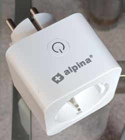
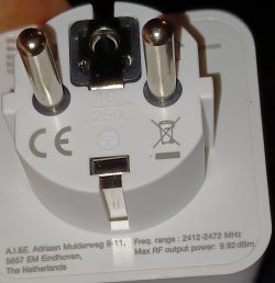
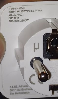
I see a reference number 26545 and the model says SPL-W-TY-PM-EU-RY 10A.
It's a product which is distributed by the Dutch company A.I.&E. I had never heard of it...
Disassembling the plug wasn't too difficult.
Wiggeling with a small screwdriver and pulling away the outer cap (which contains the button) was straight forward and not so difficult.
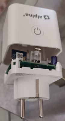
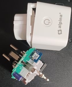
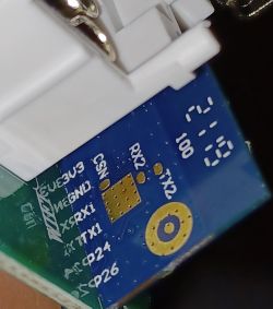
On the inside there is immediately the blue CB2S WiFi PCB visible, which contains the BK7231N chip.
There is also a measurement chip with the reference "BL 093", though I couldn't red the last digit of that reference.
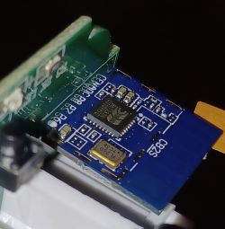
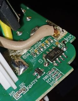
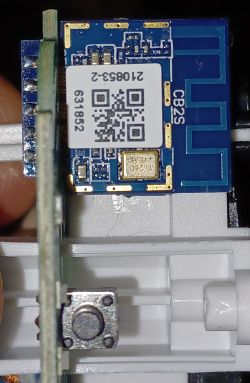
I unsoldered and removed the blue CB2S PCB and flashed it with the flashing tool that I found on this github website : https://github.com/openshwprojects/BK7231GUIFlashTool
For doing so, I connected 3V3, GND, RX1 and TX1 with an USB UART device, connected to com3. Then I downloaded the existing firmware and flashed the most recent open source firmware (OpenBK7231N_QIO_1.17.603) which can be downloaded directly via the flashing tool.
Here is the original firmware :
During flashing this screen appeared with information about the pins assignment :
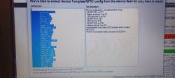
After resoldering the CB2S and re-assembling the plug, I connected to the OpenBK wifi hotspot, connected to the IP address 192.168.4.1 of the plug and entered the info from my local SSID and my MQTT server.
The plug was then accessible on my local WiFi network.
I filled in the pin setting as follows :
And this is the associated template :
I found an Autoexec file in another post here in the forum and copied this in the file system as autoexec.bat with the following content :
After all this, the plug was found and integrated automatically (after some time) in Home Assistant.
That's all folks.
It said it was remotely controllable with an app Alpina Smart.
This is how it looks after unboxing :


I see a reference number 26545 and the model says SPL-W-TY-PM-EU-RY 10A.
It's a product which is distributed by the Dutch company A.I.&E. I had never heard of it...
Disassembling the plug wasn't too difficult.
Wiggeling with a small screwdriver and pulling away the outer cap (which contains the button) was straight forward and not so difficult.


On the inside there is immediately the blue CB2S WiFi PCB visible, which contains the BK7231N chip.
There is also a measurement chip with the reference "BL 093", though I couldn't red the last digit of that reference.


I unsoldered and removed the blue CB2S PCB and flashed it with the flashing tool that I found on this github website : https://github.com/openshwprojects/BK7231GUIFlashTool
For doing so, I connected 3V3, GND, RX1 and TX1 with an USB UART device, connected to com3. Then I downloaded the existing firmware and flashed the most recent open source firmware (OpenBK7231N_QIO_1.17.603) which can be downloaded directly via the flashing tool.

Here is the original firmware :
ADVERTISEMENT
During flashing this screen appeared with information about the pins assignment :

After resoldering the CB2S and re-assembling the plug, I connected to the OpenBK wifi hotspot, connected to the IP address 192.168.4.1 of the plug and entered the info from my local SSID and my MQTT server.
The plug was then accessible on my local WiFi network.
I filled in the pin setting as follows :
* pin 6 : LED channel 0 - red led related to the switching relais
* pin 7 : Btn channel 0 - button on the smart plug
* pin 8 : Rel channel 0 - the contact of the relais
* pin 10 : WifiLED_n channel 0 - blue flashing LED during connection process to the WiFi network
* pin 11 : BL0937SEL channel 0
* pin 24 : BL0937CF channel 0
* pin 26 : BL0937CF1 channel 0
And this is the associated template :
Code: JSON
I found an Autoexec file in another post here in the forum and copied this in the file system as autoexec.bat with the following content :
// Start NTP Driver
startDriver ntp
// Set NTP Server
ntp_setServer 95.216.138.141
// Set timezone
ntp_timeZoneOfs +01:00
// Set Periodic Statistics for Power Measurements
SetupEnergyStats 1 60 60
mqtt_broadcastInterval 120
// VCPPublishTreshold to reduce mqtt-traffic
VCPPublishThreshold 2 0.5 2
After all this, the plug was found and integrated automatically (after some time) in Home Assistant.
That's all folks.


