logo elektroda
logo elektroda
X
logo elektroda

How to Enable PWM Dimming on LN882HKI Tuya Smart LED Controller with OpenBeken?

acbrooks 2100 37
ADVERTISEMENT
  • #1 21153537
    acbrooks
    Level 2  
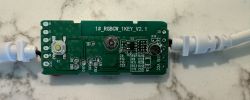
    I successfully flashed OpenBeken to a LN882HKI device in the pictures. The device is a led panel for indoor plants: https://www.mother.life/BE/shop/linear
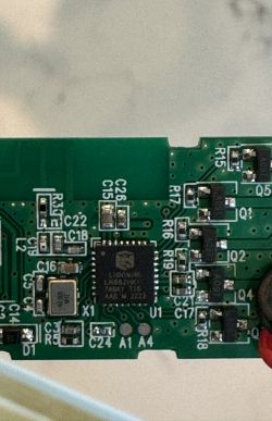
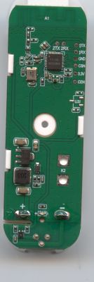
    Close-up of a circuit board showing the LN882HKI chip and electronic components. Printed circuit board with connected cables, viewed from above. Image of a circuit board labeled 1#_RGBCW_1KEY_V2.1, connected with cables, placed on a white marble surface.

    I can control on/off with LED or relay on A10 but it will not work with PWM. The local button works properly on B4 as seen in the config:
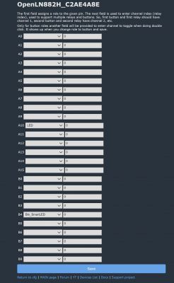
    Screenshot of the OpenLN882HKI device configuration with pin settings.

    I cannot get the device to dim, however, which I'm guessing stems from PWM not working. Anyone have any ideas? I can provide more info from the Web App if needed.
  • ADVERTISEMENT
  • #2 21153576
    p.kaczmarek2
    Moderator Smart Home
    From a brief glance, it seems that PWM is not yet implemented on LN882HKI:
    https://github.com/openshwprojects/OpenBK7231T_App/blob/main/src/hal/ln882h/hal_pins_ln882h.c
    Code: C / C++
    Log in, to see the code

    We need to check their SDK and add missing PWM calls. Would you like to help?
    Helpful post? Buy me a coffee.
  • #3 21154103
    acbrooks
    Level 2  
    Yes, I can help with info from my device or testing.
  • #4 21159267
    parlaystaller_0d
    Level 5  
    Hi, did you manage to get this working?
    I am running into the same issue.
  • #5 21159320
    acbrooks
    Level 2  
    Not yet. I will need some handholding to provide whatever information is needed to get PWM working in this module.
  • #6 21159337
    p.kaczmarek2
    Moderator Smart Home
    There are some PWM mentions in SDK:
    https://github.com/search?q=repo%3Aopenshwprojects%2FOpenLN882H+pwm&type=code
    This seems to be a PWM header:
    https://github.com/openshwprojects/OpenLN882H...ripheral_driver_demo/PWM/bsp/ln_drv_pwm.h#L42
    But how do we know how to map PWM channels to GPIOs?
    Helpful post? Buy me a coffee.
  • ADVERTISEMENT
  • #7 21159401
    parlaystaller_0d
    Level 5  
    I would be willing to help but I don't have any experience with either low level hardware debugging or C coding...
    So, if there is anything I can do please tell me.
  • #8 21180696
    parlaystaller_0d
    Level 5  
    Does anybody know someone who can help out with this?
  • #9 21181652
    divadiow
    Level 34  
    I'm afraid I am not able to assist with this.
  • #10 21181670
    p.kaczmarek2
    Moderator Smart Home
    Well, here is a full PWM sample:
    Code: C / C++
    Log in, to see the code

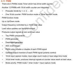
    We just need to find which port/pin combination is using which PWM channel. Maybe in some datasheet?
    Helpful post? Buy me a coffee.
  • ADVERTISEMENT
  • #12 21188527
    parlaystaller_0d
    Level 5  
    >>21181676 does this datasheet help us with understanding which pins are used together for PWM?

    I don't really know how to read this sheet and what to take from it...
  • #13 21190197
    divadiow
    Level 34  
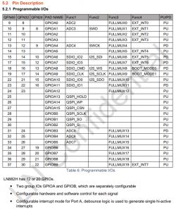
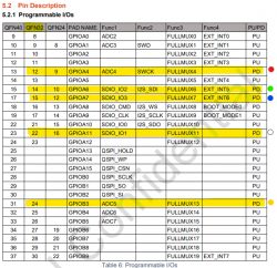
    all I can add really is that our LN882HKI chips are QFN32 packages so the GPIOs that are FULLMUX, which I think includes PWM support, are

    GPIOA0: Pin 8
    GPIOA1: Pin 9
    GPIOA2: Pin 10
    GPIOA3: Pin 11
    GPIOA4: Pin 12
    GPIOA5: Pin 13
    GPIOA6: Pin 14
    GPIOA7: Pin 15
    GPIOA8: Pin 16
    GPIOA9: Pin 17
    GPIOA10: Pin 21
    GPIOA11: Pin 22
    GPIOA12: Pin 23
    GPIOB3: Pin 24
    GPIOB4: Pin 25
    GPIOB5: Pin 26
    GPIOB6: Pin 27
    GPIOB7: Pin 28
    GPIOB8: Pin 29
    GPIOB9: Pin 30
  • #14 21194617
    divadiow
    Level 34  
    maybe @max4elektroda or @insmod are in a position to assist
  • ADVERTISEMENT
  • #16 21199706
    parlaystaller_0d
    Level 5  
    >>21195618 thanks for providing an example.

    I guess the next info I need is, how to find and configure PWM pins.
    How do I know which of them is/are responsible for dimming the light?

    Next, did I understand correctly, that I have to configure a PWM pin that controls channel 4?
    When you look at the PCB, there are wires to C and V.

    The current configuration has a pin configured as LED controlling channel 0.
    And a button_SmartLED controlling channel 0.

    Screenshot of the GPIO Doctor Pins interface with a list of pins and their configuration.
  • #17 21199714
    insmod
    Level 22  
    >>21199706 If you are able to turn on/off light with LED on P10 pin, then just change LED to PWM. While your board has full rgbcw pins, only c is wired, so channels don't matter.
  • #18 21199833
    parlaystaller_0d
    Level 5  
    >>21199714 hmm ok, thanks for the info.

    I figured out. why it is not working.
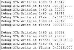
    Somehow the OTA does not work.
    When I try to upload your example binary, It says, starting OTA... But thats it. It does not reboot.
    Do you have an idea?

    Screenshot of the OTA update process with debug messages.

    Added after 14 [minutes]:

    >>21199714 I got it wokring. I uploaded with another browser. Somehow Firefox had an issue with it ¯\_(ツ)_/¯

    One last question, would mind, creating a PR with your changes?
    I know it isn't finished but it at least works almost :)

    I now have the issue, that MQTT disconnects and connects repeatedly and resets the light to a dimmed value.
    Maybe there is some loop?
  • #19 21199881
    insmod
    Level 22  
    >>21199833 Will open, though first I have to remove the dependency on the driver from SDK. It will take some rewriting, but easily doable.
  • #20 21199913
    parlaystaller_0d
    Level 5  
    >>21199881 Thank you very much!
  • #22 21201702
    p.kaczmarek2
    Moderator Smart Home
    Thank you, merged. So you basically pick first unused pwm channel?
    Helpful post? Buy me a coffee.
  • #24 21223672
    parlaystaller_0d
    Level 5  
    Sometimes I have the issue, when it loses the connection to the MQTT server and it reconnects, it turns on the light to about 1 or 2 percent.
    I don't know if this is specific to this controller but I don't think so.
    Do you have any advice for that issue?
  • #27 21223716
    insmod
    Level 22  
    >>21223713 Yes, i verified that it works on a single rgb led. The only drawback, is that it reduces the available channels to 6, instead of 12.
  • #28 21223724
    p.kaczmarek2
    Moderator Smart Home
    Can you explain what is the logic behind those "channels" on LN882H and why do we have to choose?
    Helpful post? Buy me a coffee.
  • #29 21223729
    insmod
    Level 22  
    >>21223724 Each pwm timer have 2 channels, but when second channel is picked, it somewhy doesn't work. So rgb led witch channels 1r 2g 3b, the green channel didn't work. In my pr, it will select only first timer channel for each pwm channel.
  • #30 21224383
    divadiow
    Level 34  
    on 1331_merge_fe57bd70ce5e with these assignments

    Code: Text
    Log in, to see the code

    which translates to:
    Table of programmable I/O ports description for a microcontroller.

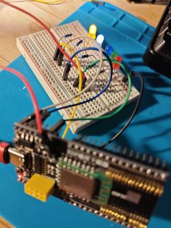
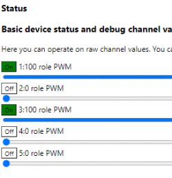
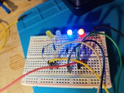
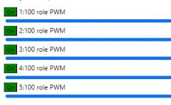
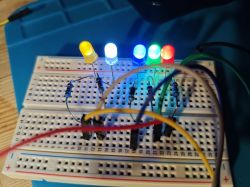
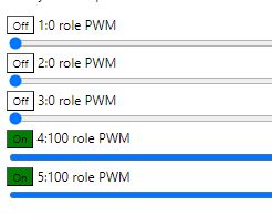
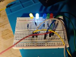
    I have 5 working LEDs, controllable as one would expect. Dimmable, colour picker, warm/cold


    LED control interface with sliders for adjusting brightness, color, and temperature. Close-up of a breadboard prototype with five functioning LEDs in different colors connected to a microcontroller.


    Screenshot showing device status with five PWM channels. Channels 1 and 3 are on, and channels 2, 4, and 5 are off. Circuit on a breadboard with five lit LEDs.


    Five rows showing the operation of LEDs controlled by PWM. Five lit LEDs on a breadboard, displaying different colors.


    LED control list with PWM labels, showing On/Off status for each. Five LEDs on a breadboard with multicolored lighting


    so all looks good.

Topic summary

The discussion revolves around enabling PWM dimming on the LN882HKI Tuya Smart LED Controller after flashing it with OpenBeken firmware. Users report that while they can control the device's on/off state, PWM functionality is not operational. Initial investigations reveal that PWM support may not be fully implemented in the current SDK. Participants share code snippets and suggest checking GPIO mappings for PWM channels. A user successfully uploads a PWM example, leading to further inquiries about configuring PWM pins and addressing issues with MQTT disconnections. Ultimately, a pull request (PR) is created to enhance PWM functionality, which is confirmed to work with multiple LED channels, allowing for dimming and color control.
Summary generated by the language model.
ADVERTISEMENT