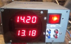
Hello  .
.
I have been planning for quite a long time to build a device to indicate the current electricity consumption in the house. The problem was that there was no way to connect to the power supply in the meter box. Pulling additional cables meant devastating part of the building.
So a wireless LED flashing transmitter for the electricity meter was created.
I have made remote sensors for the weather station using a similar system.
Transmitter:
The processed LED flashes are sent by the ESP8266 chip using the ESP NOW protocol.
The conventional counter number and power cell status are sent.
In the idle state, the ESP is plunged into a deep sleep .
.
Current consumption in this state is about 160uA (could be less).
The photoresistor is incorporated into a comparator circuit on the LMV358, the output of which controls a transistor that provides a low state that resets the ESP circuit when the counter LED flashes. After waking up and sending data, the MCU falls into a deep sleep.
The whole thing is powered by an 18650 cell.
The transmitter software needs to be discussed. Anyone who has dealt with ESP NOW with a receiver connected to WiFi has encountered the problem of changing the channel on the transmitter. Connecting the ESP NOW receiver to a WiFi network, has the effect of changing the default 1 ESP channel to a WiFi channel.
The transmitter does not know this and transmits on channel 1 (no communication).
In this case, the transmitter has two automatic modes of operation.
In scan mode, the transmitter in ESP NOW mode looks for a receiver with a specific MAC. It sends a query to it sequentially on each channel until a response is received. After a positive response, the channel number from which the response came is stored in the RTC memory. This memory is not erased on subsequent ESP restarts. Scanning the channels takes approximately 300ms.
I have also made a small adjustment in case of interference during data transmission.
Each time data is sent, the receiver sends back an acknowledgement to the transmitter that it has received it. The next scan takes place after two unconfirmed transmissions.
Receiver:
Example demo. ESP8266 connected to a WiFi network, generates a web page. An Ajax script refreshes the data on the page.
The operation of the program is to convert to kW an incremented timer (1kHz) variable between successive received data (LED flashes) from the transmitter. This can be done in any other way. Also the calculation of kWh.
Transmitter design:
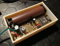 .
.
Short demonstration video:
Diagram:
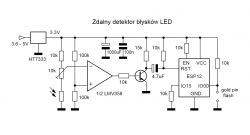
ESP8266.
Current consumption. Channel scan oscillogram.
Here you can see 13 WiFi channels (about 300ms).
 .
.
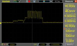
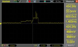
Oscillogram after LED flash detection:
Total time from wake-up to sleep about 180ms.
I am puzzled by this second pin....
Transmitter and receiver sources attached. MCU software written in the Arduino IDE.
I have been planning for quite a long time to build a device to indicate the current electricity consumption in the house. The problem was that there was no way to connect to the power supply in the meter box. Pulling additional cables meant devastating part of the building.
So a wireless LED flashing transmitter for the electricity meter was created.
I have made remote sensors for the weather station using a similar system.
Transmitter:
The processed LED flashes are sent by the ESP8266 chip using the ESP NOW protocol.
The conventional counter number and power cell status are sent.
In the idle state, the ESP is plunged into a deep sleep
Current consumption in this state is about 160uA (could be less).
The photoresistor is incorporated into a comparator circuit on the LMV358, the output of which controls a transistor that provides a low state that resets the ESP circuit when the counter LED flashes. After waking up and sending data, the MCU falls into a deep sleep.
The whole thing is powered by an 18650 cell.
The transmitter software needs to be discussed. Anyone who has dealt with ESP NOW with a receiver connected to WiFi has encountered the problem of changing the channel on the transmitter. Connecting the ESP NOW receiver to a WiFi network, has the effect of changing the default 1 ESP channel to a WiFi channel.
The transmitter does not know this and transmits on channel 1 (no communication).
In this case, the transmitter has two automatic modes of operation.
In scan mode, the transmitter in ESP NOW mode looks for a receiver with a specific MAC. It sends a query to it sequentially on each channel until a response is received. After a positive response, the channel number from which the response came is stored in the RTC memory. This memory is not erased on subsequent ESP restarts. Scanning the channels takes approximately 300ms.
I have also made a small adjustment in case of interference during data transmission.
Each time data is sent, the receiver sends back an acknowledgement to the transmitter that it has received it. The next scan takes place after two unconfirmed transmissions.
Receiver:
Example demo. ESP8266 connected to a WiFi network, generates a web page. An Ajax script refreshes the data on the page.
The operation of the program is to convert to kW an incremented timer (1kHz) variable between successive received data (LED flashes) from the transmitter. This can be done in any other way. Also the calculation of kWh.
Transmitter design:
 .
.
Short demonstration video:
Diagram:

ESP8266.
Current consumption. Channel scan oscillogram.
Here you can see 13 WiFi channels (about 300ms).
 .
.
Oscillogram after LED flash detection:
Total time from wake-up to sleep about 180ms.
I am puzzled by this second pin....

Transmitter and receiver sources attached. MCU software written in the Arduino IDE.


