logo elektroda
logo elektroda
X
logo elektroda

Low-cost water heating project from photovoltaic overproduction on ESP8266 and Tasmota

Daro1003 5205 26
ADVERTISEMENT
Treść została przetłumaczona polish » english Zobacz oryginalną wersję tematu
  • Over-production water heating for PV users under new billing rules.

    I would like to present a low-cost project that can be done by anyone who likes electronics and happens to hold a soldering iron in their hand.
    The project is designed to switch on the heater when our photovoltaic installation generates a certain power. A control problem often encountered by users of photovoltaic installations - i.e. how to heat water when it is lit.

    The system I have presented is very simple to build and cheap, it does not have advanced functions like the systems you can buy for over a thousand zlotys, but I think it will certainly help.

    Everything is based on a circuit:
    1. ESP8266
    PZEM 004-t module, which sees the flow of power with current regardless of the direction, so the final assembly is important to be on a direct wire from the inverter.
    3. Free software TASMOTA which we win to the ESP8266 using e.g. NodeMCU Flasher .

    The elements I used in the project are:

    1. PZEM 004-t measuring module
    2. ESP 8266 + board with 5V stabilizer because I just had it, but we can use wemos D1 mini or NodeMCU then we won't need USB TTL programmer but just USB cable from phone to program wemos. For those new to the subject, I would recommend buying a Wems D1 mini, it has everything you need on board for programming and operation once the tasmot is loaded.
    3. a button - which will be used to put the ESP into a configuration state.
    4. wires to connect the ESP8226 to the input of the PZEM 004-t Module, you can also buy the original cable with plug that fits the PZEM 004-t.
    5. the female-to-female wires will also be useful if you purchase the Wemos D1mini.
    6. 5V relay module
    7. 5V power supply - a phone charger can be used.
    8. Tasmota software and NodeMCU Flasher links above.
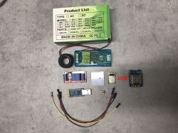
    Components for a heater control project in a photovoltaic system. .

    How to connect the module
    PZEM to ESP there is a lot of this on the internet, as well as how to upload the Tasmota and its first start-up. I do not want to duplicate these instructions here, they can be found on google.
    Borrowed diagram from google:
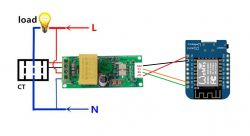
    Wiring diagram of PZEM module to ESP8266 .

    We connect the PZEM module to GPIO 4 and GPIO 5 GPIO 4 TX PZEM to GPIO 5 RX PZEM.
    We connect the relay module to the free GPIO.
    To GPIO 0 and to GND we connect the button giving GND to GPIO0 6 times puts the module into hot-spot mode while giving GND to GPIO while turning on ESP puts it into flash mode.

    After loading the tasmota and the first start-up, having the ESP with the tasmota already in our local network, we move on to the module settings:
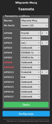
    Screenshot of Tasmota configuration showing GPIO port settings. .

    Such settings we save the module restarts and we have the screen:
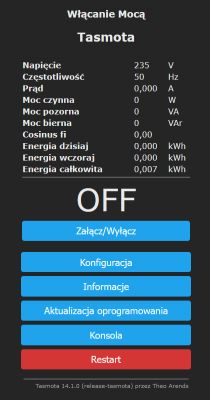
    User interface for the Tasmota system displaying voltage and power data. .

    We can check if our relay is working and if we have voltage on the PZEM
    Of course we connect 230V to the PEM according to the diagram above.

    I for testing did it like this:
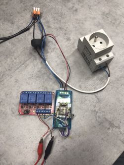
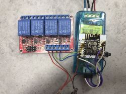
    ESP8266 module with relay module and wiring. ESP8266 and PZEM 004-t modules connected to a 4-channel relay .

    The picture shows a 4 channel relay module connected under two GPIOs because I was testing two rules which are designed to switch on individual relays at different powers. That is, for example, the power going through the PZEM, e.g. above 2000W turns on relay 1, the power going above 3000W turns on relay 2.

    How much power we set is an individual matter.

    Another key setting is the rule by which the whole system works. A rule borrowed from another forum from my colleague isom to whom I thank for his kindness.

    Go to the console tab:

    We specify the key rule to run.

    Rule1 on Energy#Power>2000 do Power1 1 ENDON on Energy#Power<2000 do Power1 0 ENDON
    .

    And enabling the rule to make it work:

    Rule1 on
    .

    In the first part of the rule:
    Energy#Power> 2000 - we specify from above what power the relay should turn on.

    In the second part of the rule:
    Energy#Power< 2000 - we specify from below what power the transmitter should switch off.

    Now checking that everything is working is enough to mount it in the switchgear.
    We mount the measuring clamp on the phase conductor going directly from the inverter and take 230V from the same phase to the PZEM.
    The PZEM module sees the power and current flow no matter which way it flows, so we have to mount it directly on the wire from the inverter.

    The cost of the whole project should not exceed 100zł even if you buy the components on allegro.

    I encourage colleagues to discuss and comment on my idea, maybe thanks to colleagues from Smart Home IoT the project will get more functions and will be extended.

    I have also made a project on 3 PZEM modules which monitors the energy consumption for the house was mounted directly on the power supply of the distribution blocks for the protection on the house. The inverter has been plugged in front of the blocks that supply the house thanks to this in tasmotoa I can see the energy consumption of the house and the current power flowing from the inverter.
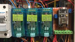
    Relay modules and ESP8266 on a prototype board in an electrical distribution box. .

    The above project has not yet gained a casing is currently a prototype but I think that the casing and implementation will already be an individual matter of each, I wanted to throw in a general idea of making such a control for water heating counting on the ideas of other more experienced users in the software Tasmota and ESP8266.

    Cool? Ranking DIY
    About Author
    Daro1003
    Level 33  
    Offline 
    Daro1003 wrote 2523 posts with rating 538, helped 268 times. Live in city Szerzyny. Been with us since 2008 year.
  • ADVERTISEMENT
  • #2 21178285
    __Maciek__
    Level 20  
    Not a bad idea, but ...
    - It would be useful to have some kind of hysteresis ... or a timer, so that the relay doesn't click like crazy at the limit (for this, a properly located current measurement).
    - With - net billing - the net works like a battery with a short holding time ... so you can accumulate for 50 minutes and use it up in the last 10 minutes ( unless 15 minute timers come in ) - a more sophisticated system could use this free battery to the full.
  • #3 21179148
    michal.zd
    Level 28  
    Daro1003 wrote:
    Module PZEM 004-t which sees the flow of power o current regardless of direction
    .
    Do I understand this correctly? There is no information about the direction of energy flow, so you used it to measure the actual power generated by the pv inverter?
    If so, it is simpler to read this directly from the inverter. There are two methods.
    You can parse the information from the html, a simple GET to the appropriate port on the inverter.
    The best way is to use Modbus data. This is what I did too, in addition I also have phase voltage information, which I use to react to a rise above the norm.
    I wrote myself a broker between the inverter and the MQTT server.
    The code is available on my git https://github.com/michalzd/pvInverterBroker/tree/mqtt
    for a sofar ktlx-g3 inverter with a wifi logger attached. It is written so that it can be compiled and run on routers with OpenWrt. To do this you still need the https://github.com/michalzd/MQTT_LinuxLib library.
    The current compilation in the repo is for the raspberry pi zero W, and A, Aplus. Previously it was just running on a tplink tlwr 740n, but the router died after a few years. It now runs on the rpi A, as an mqtt server and nodered control logic is needed anyway. The price of these rpi is so low that it makes no sense to combine with a router. The executive module is a Sonoff 4ch with the firmware changed to AFEfirmware. For my part, I recommend this firmware, it is very easy to configure and stable as a rock.
    Adding another inverter is no problem, you just need to know the registers and modbus data format. To change the code only in the following files: inverter/Sofar.c and Sofar.h
  • #4 21179171
    Daro1003
    Level 33  
    michal.zd wrote:
    Do I understand correctly? There is no information about the direction of the energy flow, so you used it to measure the actual power generated by the pv inverter?


    This is exactly why the installation of a measuring clamp is important.

    A project for people like me who only use off-the-shelf software.

    Tell me more about how to construct your project and I will be happy to test it on my Sofar Safar HYD15KTL-3PH inverter.

    I must admit, however, that the design you presented is less impressive but certainly much simpler to implement.
  • ADVERTISEMENT
  • #5 21179301
    michal.zd
    Level 28  
    The program can be compiled on any Linux. The test version was run by me on a normal Debian laptop. I can upload the binaries to git as well.
    There are two in total, a broker and a library.
    For the rpi with the Broadcom BCM2835 SoC[3], which consists of the ARM1176JZF-S processor, you can download the binaries from the dist subdirectories....
    I'll have a moment, I'll describe in github how to run the broker.

    Added after 4 [minutes]: .

    Daro1003 wrote:
    It has to be said, however, that the design presented by me is less impressive but certainly much simpler to realise.

    Yes,
    It can also be adapted to use my broker, as it also has an interface via UDP.
    Then information about the status of the inverter and the network will be sent from the broker as a structure.

    Added after 3 [minutes]:

    Daro1003 wrote:
    HYD15KTL-3PH
    .
    The data available via Modbus is probably identical across the Sofar family.
    In addition there is also information about the status of the energy storage.
    Do you have a wifi logger for it?
  • #6 21179322
    Daro1003
    Level 33  
    michal.zd wrote:
    Do you have a wifi logger for it?


    Yes I have one connected to the app.

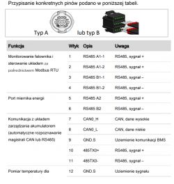
    I also have pin 1 and 3 out for communication and pin 5 and 6 used for communication with the meter it works with.

    Table of pin assignments and connection diagram for inverter and measurement devices. .

    I tried to communicate this with the RBPi on which I have Domoticz. But somehow I failed.
    Topic about this where someone even created a plugin for this but you still have to set up other topics and I relented.

    If I managed to get all the available data from Sofar into domoticz it would be fun to use. So far in domoticz I only have what the reading from tasmota allows me to do.
  • #7 21179328
    michal.zd
    Level 28  
    Which rpi do you have? Version.
    The current version communicates with the logger via wifi.
  • #8 21179332
    Daro1003
    Level 33  
    All on 3B+ with SSD to somehow make domoticz work stably. I also have a broker on it for integration with Tasmota, AFE or others.
  • #9 21179341
    michal.zd
    Level 28  
    Ok, and do you have mosquitto there? The mqtt server is needed to send data to domoticz. Broker - is that what you mean by mqtt?
    I use nodered, it's more transparent for me compared to domoticz.
    I think even domoticz needs it?
  • #10 21179402
    Daro1003
    Level 33  
    michal.zd wrote:
    Ok, and do you have mosquitto there?
    .
    I do.
    michal.zd wrote:
    I use nodered, it is more transparent for me compared to domoticz.
    .
    Unfortunately NodeRed I have nothing about it I don't know what and how.
    michal.zd wrote:
    I guess even domoticz needs it?
    .
    Apparently so, and not much can be achieved in domoticz without it, but I have no knowledge of it at all, so I am somehow combining things differently. Surely with it a lot of information from various devices would be gained in domoticz.
  • ADVERTISEMENT
  • #11 21179432
    michal.zd
    Level 28  
    Daro1003 wrote:
    NodeRed I don't have anything about it I don't know what or how.

    it's great, there's basically nothing you can't do on it.
    domoticz it doesn't even compare with nodered along with dashboard.
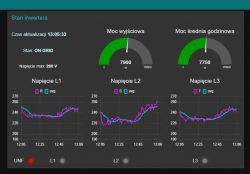
    see example view with nodered, i took a screenshot a while ago.
    Screenshot of a Node-RED dashboard displaying inverter status and voltage graphs for three phases. .
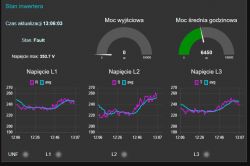
    and this is in a minute:
    Screenshot of the Node-RED interface displaying inverter status and voltage charts. .

    The status of the inverter is itself transmitted via mqtt from my broker.
    The data for the voltage graphs also, the pink line is the instantaneous voltage, while the turquoise line is the average voltage over the last ten minutes. This data serves as input to the block responsible for keeping the voltages normal, switching on the heaters in the buffer. If possible, of course, because sometimes the mains voltage is so high that no amount of power will help. Fortunately, such a situation is not frequent, and also the duration is several minutes. But thanks to the fact that I know that at this point my inverter has switched off, I also switch off the heaters. The controller logic is just written in javascript and works as a 'node' in nodered. The status is shown at the bottom as a light with a 'UNF' label indicating which phase has exceeded the voltage (this still needs to be worked out, it's fresh functionality)
    I also have domoticz, but after struggling for a few hours to integrate it with my broker, it turned out that nodered was the necessary middleman here. As soon as I started using nodered, I realised that domoticz here was really completely missing the point, just consuming memory and prock percentage. It flew out of rpi, I only have nodered.
    It's worth a go, I was already able to do what I want in it after two days of learning. Javascript is a simple language, and there is no need to use it as long as the 'node' blocks available in nodered are sufficient.

    Added after 1 [minute]: .

    Daro1003 wrote:
    I'm sure it would benefit a lot in domoticz information from different devices.

    After a few days of using nodered you will come to the same conclusion as I did: and on Pippi Långstrump mi domoticz.

    Added after 44 [minutes]:

    Quite an accessible course
    https://m.youtube.com/watch?v=9fTMpgr3EU0
  • ADVERTISEMENT
  • #12 21179545
    Daro1003
    Level 33  
    Thanks for the course, I need to start first with the installation of NodeRed.
    How better on the same RBPi as domoticz or on another ?
  • #13 21179552
    michal.zd
    Level 28  
    If you have an ssd, two side by side will do fine. Besides, you probably have GB of ram,
    Do you know a bit about Linux from the terminal side?
    There is a program called htop that shows you the current load of your machine. You can check how much ram and CPU domoticz eats, but probably not much. NodeRed on mine takes about 100MB and the CPU percentage is under 5

    Added after 32 [minutes]:

    I also looked at the discussion on the smart home forum you have a link to.
    It appears to me that this plugin is attached to the inverter via a cable connector.
    I immediately communicate via wifi with the LSW logger attached.

    Added after 28 [minutes]: .

    In order for you to test my broker, you need to compile these two programs at your Raspberry, I have a different processor in my rpi.
    Some preparations needed for compilation:
    1. a 'C' compiler along with the necessary libraries:
    https://linux.how2shout.com/hwo-to-install-build-essential-on-debian-such-as-12-and-11/

    2. the first program needed is the library https://github.com/michalzd/MQTT_LinuxLib
    you can download it in two ways:
    way 1: download the repository as a zip by clicking on the green 'Code' button and unzip in any user directory on the rpi, e.g: /home/user_name/MQTT_LinuxLib
    method 2: install git on the malinka:
    # sudo apt-get install git git-core
    # cd ~
    # mkdir MQTT_LinuxLib
    # cd ./MQTT_LinuxLib
    # git clone https://github.com/michalzd/MQTT_LinuxLib.git

    3. after that in the MQTT_LinuxLib directory
    # make

    should compile. once you have that, I'll tell you what to do next.

    Added after 15 [minutes]: .

    I also have an rpi 4 with an ARM-8 Cortex-A72 processor, the 3 has an ARM-8 Cortex-A53.
    I wonder if they are compatible from the code side. I can run a test. I will prepare a simple test program to run at your place. If it runs without a problem, I will compile the broker at home.

    Added after 1 [hour] 1 [minute]: .

    First attempt, compile a simple test on a raspberry pi 1 B (mine) with the compiler flag -mcpu=cortex-a53 -mfpu=neon-fp-armv8 .
    upload it to your home directory and fire it up. See if it works.
    only after copying it to the raspberry you need to give it the rights to run:
    # chmod a+rwx ./testcortexa53.bin
  • #14 21179926
    Daro1003
    Level 33  
    @michal.zd I very much appreciate your work and commitment but you approach the subject in a very advanced way. Personally, I don't really know what to do and how with your information. I approach the subject in such a way that anyone who likes to hold a soldering iron in their hand can make something simple for their own use to heat water. In your case, as I already wrote, the idea is certainly better and more effective, because it is the data from the inverter that will play the main role, but the instructions from you are, in my opinion, for a programmer, not for an electrician who is green in programming and uses ready-made solutions.

    As the topic has gone a bit in a different direction, it would be nice to create another topic with your idea starting with what is needed for this project to be able to assemble it - I myself would be happy to order components and would like to assemble it according to your idea as I see more potential in it by using the data from the inverter. An important issue of the project is the cost - it is well known that there are already solutions of this type on the market for about 1 thousand zlotys, so if you can heat it on some cheap RBPi e.g. zero memory card and power supply or possibly a USB->RS485 converter it will be cool, but let's start from the beginning.
  • #15 21180001
    michal.zd
    Level 28  
    Daro1003 wrote:
    the instructions from you are in my opinion for a programmer
    .
    rather for someone who is already familiar with Linux and not afraid of compilation.
    That's why I asked earlier how you feel about the Linux terminal.
    But the following list of steps is not complicated ;) .
    But as recompiling for me under a different architecture is not a problem, in addition I was able to run the test on my second malinka 4, I already have some observations.
    The processor in the tinyka 4 ran the test program compiled under rpi 1 B+ without any problems. In principle, ARM Cortex-A are compatible upwards, this is just normal. On the other hand, the processor in the raspberry 1 is not cortex, this made me doubt whether the program would work.
    Also I compiled these programs for your version of the processor too, the binaries are available in my github.
    So the whole process of compiling the program is dropped, you just need to download the binary and put it in the right directory.

    For you it would be this library:
    https://github.com/michalzd/MQTT_LinuxLib/tre...dist/Release/GNU-Linux/RaspberryPi/Cortex-A53
    place the file in a directory, you don't need to do anything else
    /usr/lib

    Broker program:
    https://github.com/michalzd/pvInverterBroker/...dist/Release/GNU-Linux/RaspberryPi/Cortex-A53
    preferably in the /usr directory, create a directory like the following and put the binary there
    /usr/inverter
    You will probably even very much have to give this binary execution rights. The easiest way to do this is with mc.

    For this you still need the configuration file from
    https://github.com/michalzd/pvInverterBroker/tree/mqtt/etc
    and put it into (you also need to create a directory in /etc)
    /etc/ime
    In this file there will be a few lines to change:
    
    # Sofar Logger 
    logger_sn	2363445823
    logger_addr	192.168.10.70
    logger_port	8899
    
    # refresh time in sec
    refresh_time	30
    
    # broker udp port 
    service_port	8898
    
    # mqtt server  topic danych textowych oraz binarnych  
    mqtt_server		192.168.10.80:1883
    mqtt_topic		ime/inverter/
    mqtt_binary_topic	ime/inverterbin
    
    .

    at the top, the access to the logger, and the address to mosquitto - which is the same as malinka has.
    the data will be sent to the mqtt server with the topics as in the file, of course you can also change it.
    the best thing to do is to start mosquitto_sub on the tinker to listen on the topic with mqtt_topic, i.e. 'ime/inverter/#'.
    you should get information from the inverter every half minute.

    Added after 3 [minutes]: .

    For uploading files to a raspberry from Windows, download the program:
    https://winscp.net/eng/downloads.php#additional
    preferably "Portable executables", a link to which is slightly below on this page.
  • #16 21180417
    speedy9
    Helpful for users
    Tuya makes ready-made modules that additionally detect the direction of current flow. So if someone is using the Tuya system anyway, there is no simpler or cheaper way to realise the above functionality. A module with a single-point measurement costs about PLN 70, a two-point module about PLN 85. It is possible to configure dependencies, enter hysteresis.
  • #17 21180429
    Daro1003
    Level 33  
    speedy9 wrote:
    uya makes ready-made modules that additionally detect the direction of current flow.
    .
    You can insert a link I will be happy to test.
  • #18 21180439
    speedy9
    Helpful for users
    Even cheaper than I wrote before: https://www.aliexpress.com/item/1005005885768083.html
    I am thinking of buying a similar module, but a three-phase one: https://www.aliexpress.com/item/1005006456832377.html Rather out of curiosity, as I have a PV under the old rules and don't really have a need to use the surplus somehow. Rather out of curiosity as to what the power consumption looks like on the individual phases.
  • #19 21180446
    Daro1003
    Level 33  
    I have a 3 phase build on a PZEM 004-t on each phase the power is identical rather there is no point in measuring from the inverter the power on each phase unless you want to use it to measure the power consumption in the house.
    Single-channel 57zl two-channel 66zl you have to order a single-channel one to test what and how you can set it there.

    We still don't have any information about the over production that the inverter has, and in total this is the most important thing, i.e. the power that goes into the grid and above e.g. 1500W we switch on the heater.

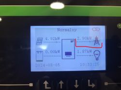
    Inverter display screen showing power generation and transmission values. .
  • #20 21180461
    speedy9
    Helpful for users
    That's why you put the measurement on the output to the grid. The direction of the current flow tells you whether you have an overproduction and send it to the grid or a shortage and take it. You can make a second measuring point on the heater. You need to think about the measurement points, especially if you have a three-phase installation and inverter.
    I'm not interested in monitoring the power on the phases from the inverter, that's what I have in the app from the inverter. However, my inverter does not show what you have on the display, because it can only do such things after attaching a so-called SmartMeter, which costs too much to satisfy curiosity ;) .
  • #21 21180468
    Daro1003
    Level 33  
    speedy9 wrote:
    SmartMeter, which costs too much to satisfy curiosity


    That's exactly how I ended up with a seller - a friend who, in the price of the inverter, gave me this meter tz. said that it comes with the inverter every other seller takes it out of the box and sells it separately.
  • #22 21180471
    speedy9
    Helpful for users
    I have a Huawei inverter and there this meter was always separate.
  • #23 21180478
    Daro1003
    Level 33  
    speedy9 wrote:
    This is why you put the measurement on the output to the grid. The direction of current flow tells you whether you have an overproduction and send it to the grid or a shortage and take it.
    .

    In a system like this it only makes sense to me to have a 3 phase to catch the overproduction in total you can catch the overproduction flying through this phase and mount a heater on this phase. Well maybe ok
  • #24 21180883
    Slawek K.
    Level 35  
    Just out of curiosity, what is the definition of overproduction in this case ?
  • #25 21182849
    chemik_16
    Level 26  
    I had about 8pc of these PRZEMs, they did not work for me. They generated a lot of "spikes", some sudden measurements of 150kW. In the event of a power cut, they went completely crazy. After half a year 4 pieces died, only the red diode was lightly lit, probably the voltage stabiliser circuits went out.
  • #26 21191474
    jaros12
    Level 12  
    >>21179148 Measurement of current alone (i.e. indirectly power) without direction of flow, can also be done without PZEM, directly on the analogue input of the ESP. All you need is a transformer for 20PLN + a few resistors and a capacitor.
  • #27 21299109
    kolo9
    Level 14  
    Daro1003 wrote:
    .
    In such an arrangement it only makes sense to me to have a 3 phase to catch the overproduction in total you can catch the overproduction flying through this phase and mount a heater on this phase. Well maybe ok
    I wonder from what date did the contracts get so unfavourable to make it worthwhile to heat from overproduction? I have a 3 phase Huawey and am facing a refurbishment as part of which it would make sense to change the CWU.

Topic summary

The discussion centers on a low-cost DIY project for heating water using surplus photovoltaic (PV) power under new net billing regulations. The core system uses an ESP8266 microcontroller combined with a PZEM-004T energy meter module to measure power flow on the direct wire from the inverter, controlled via free Tasmota firmware flashed with NodeMCU Flasher. Key challenges include detecting overproduction accurately, managing relay switching with hysteresis or timers to avoid rapid toggling, and handling three-phase installations. Alternative approaches suggest reading inverter data directly via Modbus or HTTP interfaces, enabling more precise control and integration with home automation platforms like Domoticz or Node-RED through MQTT brokers. Some users report reliability issues with PZEM-004T modules, while others recommend Tuya modules capable of detecting current flow direction, offering simpler and cheaper solutions with configurable hysteresis. The importance of measuring power flow direction at the grid output is emphasized to identify true overproduction. Discussions also cover hardware compatibility, software compilation on Raspberry Pi models, and integration complexities for users less familiar with Linux or programming. The project aims to provide a simple, affordable solution for electronics enthusiasts to utilize PV overproduction for water heating, contrasting with more expensive commercial systems.
Summary generated by the language model.
ADVERTISEMENT