logo elektroda
logo elektroda
X
logo elektroda

YAGI PCB 2.4GHz WiFi antenna for ESP-NOW

TechEkspert 4299 28
ADVERTISEMENT
Treść została przetłumaczona polish » english Zobacz oryginalną wersję tematu
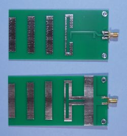
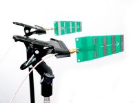
  • Two green PCB YAGI antennas on a white background.
    There are YAGI Wi-Fi PCB antennas available on Aliexpress for the 2.4GHz band. However, I didn't need such an antenna for a typical Wi-Fi card. I'm using ESP32 modules with omni-directional antennas, which transmit information between two buildings about 300m apart after ESP-NOW. One module sends information, the other receives information, it is a one-way transmission. There is no visibility between the buildings, which are obstructed by trees and other buildings. The distance of 300m is not a special achievement, as one can find information about successful attempts with ESP-NOW at 1km with optical visibility.


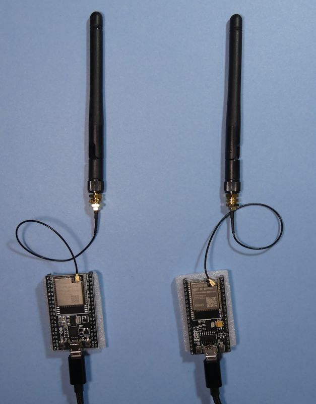
    Such a simple set-up allowed data transmission over a distance of 300m:

    Two ESP32 modules with attached omnidirectional antennas.
    .

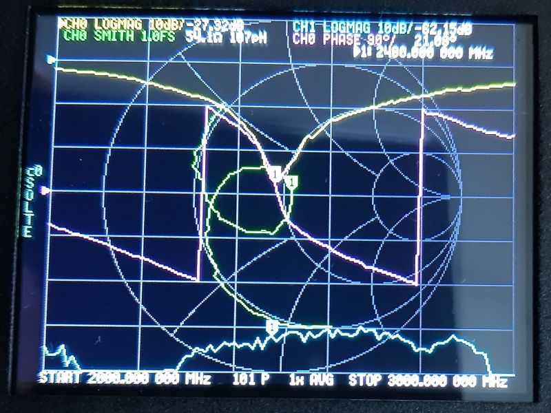
    However, sometimes all that is needed is a reinforced concrete building with a large slab in the communication path and the range barely reaches 50m or less. I had a chance to check the included omnidirectional antennas and you can see the alignment for the 2.4GHz band:

    Smith chart showing antenna characteristics for the 2.4 GHz band.
    .

    What did I need the PCB YAGI antenna for?

    I wanted to use similar connectivity between two buildings about 430m apart. This time the omnidirectional antennas did not provide transmission. Unfortunately I did not know whether the problem was the distance or the terrain obstacles. It remained to do a practical test and the PCB antenna went into the receiver.

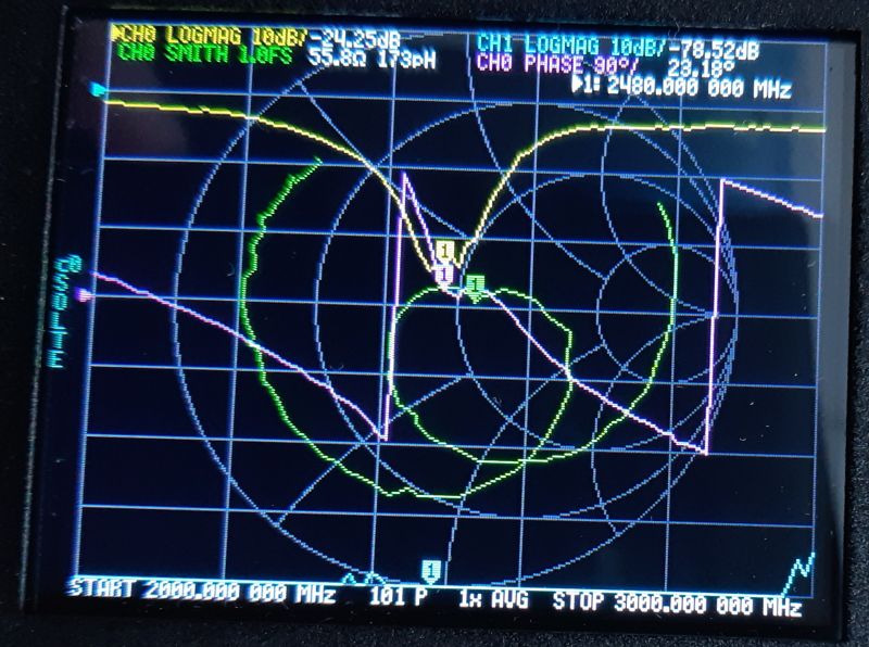
    Also, I had the opportunity to test whether the antenna responds to frequencies in the 2.4GHz band:

    Image of a spectrum analyzer screen with frequency band graphs at 2.4 GHz.
    .

    Interestingly, the PCB antenna detached when placed on a clapboard desk. Perhaps the moisture in the wood affected the antenna's performance?

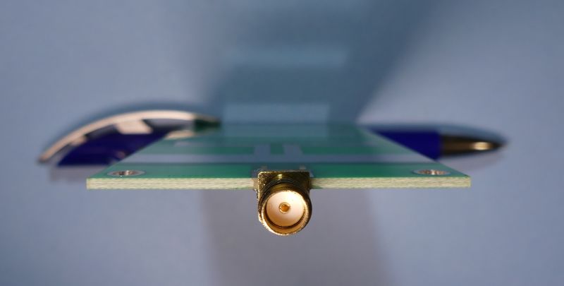
    The antenna connector required a suitable u.FL - SMA adapter:

    Side view of a PCB YAGI antenna connector with visible mounting details.
    .

    After using a YAGI antenna on the receiver, transmission over approximately 430m was possible!


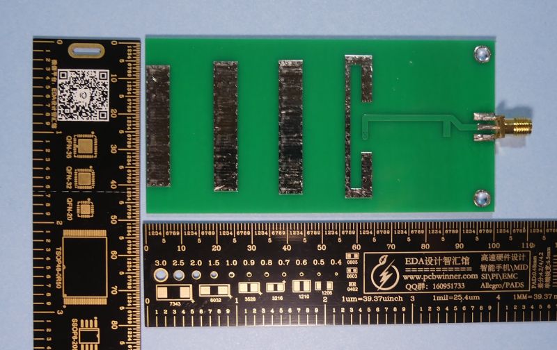
    The dimensions of the antenna are approximately 50mmx100mm so place greater mounting requirements than an omnidirectional antenna:

    PCB YAGI antenna board on green background with rulers on the side.
    .

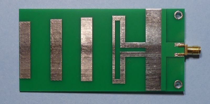
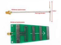
    The PCB shows three directors, a dipole and a reflector:

    PCB YAGI Wi-Fi antenna with three directors, a dipole, and a reflector.


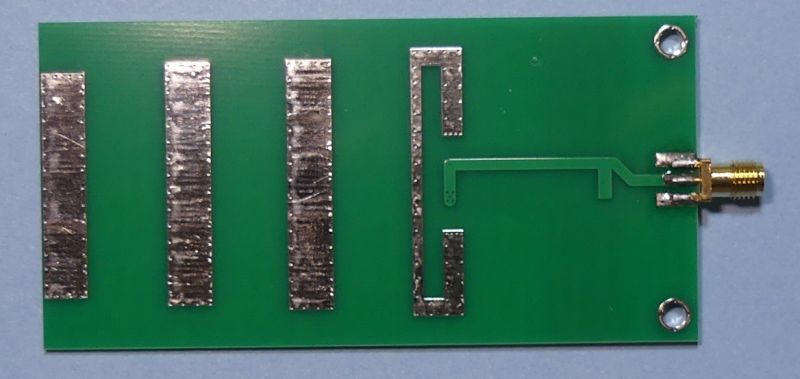
    On the other side there is some magic with the paths concerning the w.cz ;)
    Request for a hint as to what is going on here, is this some kind of impedance matching?

    PCB YAGI Wi-Fi antenna on a green board with three metal strips and a connector.


    The antenna has proved successful in providing adequate range for transmission, but it is not always possible to transmit data using ESP-NOW in the 2.4GHz band,
    urban conditions severely hamper propagation in this band. The numerous Wi-Fi APs operating in this band also do not make the task any easier.

    Have you used PCB antennas or ESP-NOW, what kind of ranges have you been able to achieve? .

    Cool? Ranking DIY
    About Author
    TechEkspert
    Editor
    Offline 
    TechEkspert wrote 6252 posts with rating 4910, helped 16 times. Been with us since 2014 year.
  • ADVERTISEMENT
  • #2 21183948
    sq3evp
    Level 37  
    A Yagi antenna is always a gain because of its directionality. For the same power, much more power radiated in the concurrent direction, also in reception increased gain.
  • #3 21184031
    ArturAVS
    Moderator
    TechEkspert wrote:
    after laying on a clinker desk board.
    .
    It is rather not clinker but furniture grade, like MDF, HDF or particleboard. In the furniture industry it is not used, if only because the surface is not very even (coarse chip).
    You made me curious about this antenna, I've been looking for a simple DIY omnidirectional antenna for a few days now. What characteristics does this one have? Probably directional?
  • ADVERTISEMENT
  • #4 21184056
    efi222
    Level 19  
    The magic mentioned may be the symmetrizer matching the impedance of the dipole to the coaxial cable.
  • #5 21184141
    sq3evp
    Level 37  
    ArturAVS wrote:
    You made me curious about this antenna, I've been looking for some simple to make DIY omnidirectional antenna for a few days now. What characteristics does this one have? Probably directional?
    .
    You've hit it - a Yagi antenna is a directional antenna as a rule.
  • #6 21184362
    TechEkspert
    Editor
    It has a directional characteristic, the transmitter had a vertical omnidirectional antenna so I vertically aligned the dipole in the receiver, then with the directors in the direction of the transmitter and found that a deviation of more than ~30 degrees causes a loss of signal.

    I could see nothing from the auction description, as it was some translation from Chinese along the lines of: "high power, low noise, range everywhere, powerful antenna, buy"....

    On the other hand, I found information that there are also PCB YAGI antennas cheated and there is an open dipole, and the connector is soldered in such a way that it makes a short circuit between the screen and the coaxial wire.

    I also looked for other types than YAGI PCBs however I eventually chose this solution. Others were panel/microstrip antennas and even a directional broadband logarithmic antenna.

    Of the DIY for Wi-Fi, the most popular are the biquad type.
  • #7 21184397
    sq3evp
    Level 37  
    TechEkspert wrote:
    From DIY to Wi-Fi the most popular are the biquad type.
    .
    Similarly a very good price/effort/effect ratio.
    I haven't tested it, I once made such an overlay for an omnidirectional antenna pretending to be a Yagi (i.e. reflector and directors, the antenna did the active element) and it worked well, but was inconvenient.
  • #8 21184543
    ArturAVS
    Moderator
    TechEkspert wrote:
    From DIY to Wi-Fi the most popular are the biquad type.

    Mine made from workshop junk and painted with some spray paint tip after 7 years;

    Cat lying on workshop roof with antenna in the background.


    I already have new cabling laid and it's practically redundant to me, but I need to put in an omnidirectional for my network instead. All I have to do is stand a few metres away and the phone loses signal. I can mount about 1.5 metres above the roof of the workshop. I am therefore looking for some simple DIY design.
  • #9 21184562
    efi222
    Level 19  
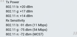
    If ESP Now packets are being lost, you could try switching the receiver and transmitter modems rigidly to the 802.11b standard.

    Table showing transmission power and reception sensitivity for Wi-Fi standards 802.11 b, g, n. .

    For the Arduino IDE ESP8266:

    extern "C" {
    #include "user_interface.h"
    }

    Setup:
    wifi_set_phy_mode(PHY_MODE_11B)
  • #10 21184575
    TechEkspert
    Editor
    The omnidirectional one should be quite simple: https://mbharris.co.uk/articles/antenna/omni/quarter/
    There are also those made from several sections of coax: http://wireless.gumph.org/articles/homemadeomni.html

    Omnidirectional biquad: https://www.youtube.com/watch?v=4t6OliwhJ5g

    2.4GHz + 5GHz: https://www.youtube.com/watch?app=desktop&v=g1S6uh7ICaI

    When WiFi emerged popular were the supposedly directional antennas from the pringles can :) .

    @efi222 that's an interesting hint, thanks!
    How does 802.11B compare with WIFI_PROTOCOL_LR ?
  • #11 21184635
    efi222
    Level 19  
    I have little experience with ESP32, but Espressif reports that up to 1km straight line range can be achieved in LR mode (ESP32 only) at the expense of speed.
    The gain over 802.11b is 4dB, which translates into 2 to 2.5 times the range of 11b mode. So much theory.
    The best way is to compare the two modes under specific conditions.
  • ADVERTISEMENT
  • #12 21184706
    austin007
    Level 17  
    TechEkspert wrote:
    When WiFi appeared, the supposedly directional antennas from a can of Pringles were popular
    .
    These canned Pringles are steamy. Apart from social media fame and ease of making, they have no merit. I made carefully, measured and was hugely disappointed. I made mine from a tin can with converted parameters. I needed a selective, sensitive 2.4GHz receive antenna. The in plus change in all parameters including s/n ratio huge.
  • #14 21186603
    khoam
    Level 42  
    efi222 wrote:
    With ESP32 I have little experience, but Espressif reports that up to 1km straight line range can be achieved in LR mode (ESP32 only) at the expense of speed.

    Unfortunately 802.11 LR mode is not supported in ESP-NOW.
  • #15 21186615
    austin007
    Level 17  
    sq3evp wrote:
    Pringles would work if they were metal like a real can.

    That's not the problem. I hadn't even considered non-metallic Prngels packaging. In a forum like this, making aerials out of these non-metal or non-metal cardboard ones should only inspire pity. The tubes have the wrong dimensions for 2.4GHz. The diameter, for example, is too small - it should be 82.7mm fi int. It will work but very suboptimally. As I wrote - made carefully according to the art it is worth recommending.
  • #18 21186653
    efi222
    Level 19  
    Still coming back to the 802.11 modes of ESP operation. I can't find what the default mode is e.g. When running ESP as a soft AP. Maybe someone has read up?
  • #19 21187419
    khoam
    Level 42  
    efi222 wrote:
    Back to the 802.11 modes of ESP operation. I can't find what the default mode is e.g. When running ESP as a soft AP. Maybe someone has read up?
    .
    You probably won't find this information in the official Espressif documentation. However, there is nothing to prevent you from checking it. For the ESP8266 you can use the function wifi_station_get_ap_info () for this, and for ESP32 esp_wifi_sta_get_ap_info ().

    I once read on the Espressif forum that the AP in the case of the ESP32 first tries to set up (negotiate) connections in 802.11n mode, and if that fails then 802.11bg. In practice, "at my place" this is what happens. How it is in the ESP8266 I have not checked.
  • #20 21190289
    Anonymous
    Level 1  
  • #21 21190458
    sq3evp
    Level 37  
    ledo99 wrote:
    PS2 now not OT - I too am in favour of biquads - with FR4 a rather poor substrate in the 2.4GHz band.
    .
    This is what somehow deterred me from trying this - FR4 has poor performance for w.h.. - The ideal would be Teflon, but I don't think there are any PCBs on Teflon.
  • ADVERTISEMENT
  • #24 21190475
    efi222
    Level 19  
    It is only the price of this Teflon plate that deters a little.
    However, the author "pulled" over 400m of range on the antenna with the FR4. In my opinion, this is a very good result.
  • #25 21190497
    sq3evp
    Level 37  
    It doesn't change the fact that the FR4 is not suitable for the VHF.
    The question is what will happen after working for a while? In the v.c. technique, Teflon offers the possibility of fairly constant parameters.
  • #26 21191720
    efi222
    Level 19  
    So, as I understand it, with such antennas, one can expect performance degradation after some time?
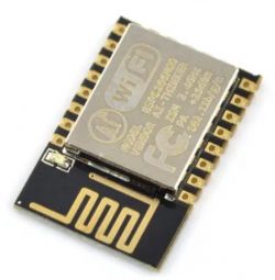
    WiFi module with built-in antenna on a white background. .
  • #27 21191994
    khoam
    Level 42  
    efi222 wrote:
    That is, as I understand it, with such antennas, performance degradation can be expected after some time?
    .
    After "some" time it is certainly ;) If the PCB is manufactured from high quality materials, the antenna can retain its performance for many years. Certainly, too high temperature or humidity affects the impedance change of such an antenna, resulting in a deterioration of its wave performance.
  • #28 21199071
    max257
    Level 10  
    I also bought the same antennas, I have similar needs, maybe a little shorter distance, about 100 m.
    I will give the details and results of measurements of the whole system- WiFi link in a separate post.

    I'll post some measurements, of course with the gain the seller exaggerated a bit - read this Link .
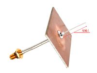
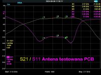
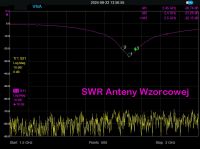
    The gain of the PCB antennas against a 1/4λ ground-plane was 7 dB, against a 1.2λ dipole(reference antenna) was 8.1 dB, SWR see screenshot - a little torii Link .
    SWRs of PCB antennas not crazy 12-13 dB. Reference dipole and ground-plane antennas at 2450 MHz SWR minimum 20 dB, reference dipole 26.7dB - see screenshot.
    Front-to-back attenuation around 14 dB - due to reflection interference it was difficult to measure this accurately.
    Noteworthy is the fact that the antenna works fairly evenly across the 2400 to 2500Mhz frequency range
    Signal level for testing 0 dBm, test distance between antennas 7 m.
    The tested antenna, in my opinion, has a flaw, it collects quite strongly from the side, the laterally placed dipole contributed to this.
    There were two antennas on the laptop and I also used these PCBs for two antennas, with one the system worked badly.
    However, they had to be at least 40 cm apart as they interfered with the transmission being close to each other (horizontal dipole).
    The antenna works quite stable in temperature and is mechanically stable.
    Mechanical distortion does not significantly affect SWR and passband.
    Like most antennas, and especially on microwaves, ours is sensitive to the immediate environment, metal objects, wooden objects.
    Placing it on a table, on the palm of your hand, etc. can shift the operating point (CF and SWR) by several tens of MHz.
    Such treatments can also lead to a condition where the antenna stops working definitively!
    The less of everything around, and especially in front, the better.
    When I buy an accurate digital protractor, I will measure the radiation angles and plot the antenna characteristics.
    Anyway, the antenna is directional and minimal deviations in direction caused significant dB drops.
    To get it to work properly, it needs to be placed in a free space, such as in a rack mount.
    This antenna is designed to work indoors, once the antenna is mounted e.g. in a yoghurt cup it will be suitable for outdoor use.
    I have already done tests and after such an upgrade with a plastic, foam lid, the parameters changed slightly - example application Link .

    In the future I will try to upgrade the antenna a bit more and put it in a proper waveguide.
    Such a solution will make the antenna more resistant to external factors, such solutions are known - see here - Link .
  • #29 21199491
    sq3evp
    Level 37  
    Antennas are from left looking:
    - yagi - directional
    - dipole - depends on how you use it - in the plane of the dipole it is bi-directional (horizontal polarisation), in perpendicular it is omni-directional (vertical polarisation)
    - 1/4 wave or as above depends on how you use it.

    Such antennas are polarised and do not radiate spherically in every direction.

Topic summary

The discussion revolves around the use of Yagi PCB antennas for 2.4GHz Wi-Fi applications, particularly in conjunction with ESP32 modules utilizing ESP-NOW for long-range communication. Users highlight the advantages of Yagi antennas due to their directional gain, which enhances signal transmission and reception over distances, especially in obstructed environments. Concerns are raised about the quality and specifications of available antennas, with some users sharing DIY solutions and experiences with various antenna types, including omnidirectional and biquad designs. The conversation also touches on the performance of different Wi-Fi standards, such as 802.11b and LR mode, and the impact of materials like FR4 and Teflon on antenna performance and longevity.
Summary generated by the language model.
ADVERTISEMENT