logo elektroda
logo elektroda
X
logo elektroda

Experience with LLXLJY 8-Channel Tuya Switch and OBK Compatibility?

io2345 3702 114
ADVERTISEMENT
  • #61 21246749
    DeDaMrAz
    Level 19  
    @io2345

    Update to latest build - 1.17.738 and use the following autoexec and please respond back.

    startDriver TuyaMCU
    tuyaMcu_setBaudRate 9600
    tuyaMcu_defWiFiState 4
    
    setChannelType 1 Toggle
    setChannelType 2 Toggle
    setChannelType 3 Toggle
    setChannelType 4 Toggle
    setChannelType 5 Toggle
    setChannelType 6 Toggle
    setChannelType 7 Toggle
    setChannelType 8 Toggle
    
    
    linkTuyaMCUOutputToChannel 1 bool 1
    linkTuyaMCUOutputToChannel 2 bool 2
    linkTuyaMCUOutputToChannel 3 bool 3
    linkTuyaMCUOutputToChannel 4 bool 4
    linkTuyaMCUOutputToChannel 5 bool 5
    linkTuyaMCUOutputToChannel 6 bool 6
    linkTuyaMCUOutputToChannel 101 bool 7
    linkTuyaMCUOutputToChannel 102 bool 8


    Again, this is without reading initial states on reboot or remembereing the states, just toggling the channels!! So whatever you have set up with original FW will still be there!!

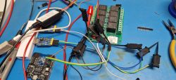
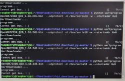
    Some pictures of the progress on my end:
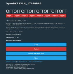
    Dashboard of the OpenBK7231N device with eight toggle buttons and system details.

    Electronic setup with multiple cables, wires, and modules on a blue workbench.
  • ADVERTISEMENT
  • #62 21247143
    io2345
    Level 7  
    DeDaMrAz wrote:
    Update to latest build - 1.17.738 and use the following autoexec and please respond back.

    Looks better. Relays can be switched on and off !!!
    Yet, some strange effects: Switching on relay 1 and after that relay 2, makes relay 1 go off. Switching it on again makes relay 1 go off. Same for 2 and 3 and combinations with relay 1. Same for combinations relay 4, 5 and 6. Relays 7 and 8 seem to not be affected.
    This strange behaviour might as well have somthing to do with the setting I did in the original FW: "Interlocking: participating=5 and number of channels per group=3"
    Will I have to flash back to original FW and reset all items, flash OBK again after that - or just wait, until "reading initial state" is implemented?
  • #63 21247189
    p.kaczmarek2
    Moderator Smart Home
    This sounds like you have interlock enabled. You can either switch back to Tuya and disable it or check out the packets you've captured and determine which packet sets the interlock. Then we can use console commands to manually send the command to disable interlock from OBK.
    Helpful post? Buy me a coffee.
  • ADVERTISEMENT
  • #64 21247345
    io2345
    Level 7  
    Works now. Did flash the Tuya-FW again and then back to OBK.
  • #65 21247351
    DeDaMrAz
    Level 19  
    So it works normally with OBK in terms of toggling relays, correct?

    We will look into reading initial state and everything else can be scripted via OBK so I wouldn't waste much time on other dpID's unless time allows.

    Let us know if you have anything else.
  • #66 21247492
    io2345
    Level 7  
    >>21247351
    Exactly, switching relays works as expected. Perfect!
    I'm fine with that. Of course it would be nice to set the initial state of the relays, but usually you do that only once. So this can be done in Tuya-FW before flashing OBK
  • #67 21247676
    p.kaczmarek2
    Moderator Smart Home
    Initial state should be very, very easy with TextField channel type, you just need to know the dpIDs....
    https://github.com/openshwprojects/OpenBK7231T_App/blob/main/docs/channelTypes.md
    Helpful post? Buy me a coffee.
  • #68 21261909
    DeDaMrAz
    Level 19  
    Since this device uses TuyaMCU for saving states and startup flags will not work I have tested the following autoexec in standalone and with HA.

    startDriver TuyaMCU
    tuyaMcu_setBaudRate 9600
    tuyaMcu_defWiFiState 4
    
    //get initial status
    tuyaMcu_sendState 191 2 16
    
    //link tuya output to OBK channels 
    linkTuyaMCUOutputToChannel 1 bool 1
    linkTuyaMCUOutputToChannel 2 bool 2
    linkTuyaMCUOutputToChannel 3 bool 3
    linkTuyaMCUOutputToChannel 4 bool 4
    linkTuyaMCUOutputToChannel 5 bool 5
    linkTuyaMCUOutputToChannel 6 bool 6
    linkTuyaMCUOutputToChannel 101 bool 7
    linkTuyaMCUOutputToChannel 102 bool 8
    
    //set OBK channel types
    setChannelType 1 Toggle
    setChannelType 2 Toggle
    setChannelType 3 Toggle
    setChannelType 4 Toggle
    setChannelType 5 Toggle
    setChannelType 6 Toggle
    setChannelType 7 Toggle
    setChannelType 8 Toggle
    
    //aliases for state saving in the tuyaMCU
    alias SAVE1 backlog tuyaMcu_sendState 191 2 103; tuyaMcu_sendState 192 2 1; tuyaMcu_sendState 193 2 1
    alias NOSAVE1 backlog tuyaMcu_sendState 191 2 103; tuyaMcu_sendState 192 2 1; tuyaMcu_sendState 193 2 0
    alias SAVE2 backlog tuyaMcu_sendState 191 2 103; tuyaMcu_sendState 192 2 2; tuyaMcu_sendState 193 2 1
    alias NOSAVE2 backlog tuyaMcu_sendState 191 2 103; tuyaMcu_sendState 192 2 2; tuyaMcu_sendState 193 2 0
    alias SAVE3 backlog tuyaMcu_sendState 191 2 103; tuyaMcu_sendState 192 2 3; tuyaMcu_sendState 193 2 1
    alias NOSAVE3 backlog tuyaMcu_sendState 191 2 103; tuyaMcu_sendState 192 2 3; tuyaMcu_sendState 193 2 0
    alias SAVE4 backlog tuyaMcu_sendState 191 2 103; tuyaMcu_sendState 192 2 4; tuyaMcu_sendState 193 2 1
    alias NOSAVE4 backlog tuyaMcu_sendState 191 2 103; tuyaMcu_sendState 192 2 4; tuyaMcu_sendState 193 2 0
    alias SAVE5 backlog tuyaMcu_sendState 191 2 103; tuyaMcu_sendState 192 2 5; tuyaMcu_sendState 193 2 1
    alias NOSAVE5 backlog tuyaMcu_sendState 191 2 103; tuyaMcu_sendState 192 2 5; tuyaMcu_sendState 193 2 0
    alias SAVE6 backlog tuyaMcu_sendState 191 2 103; tuyaMcu_sendState 192 2 6; tuyaMcu_sendState 193 2 1
    alias NOSAVE6 backlog tuyaMcu_sendState 191 2 103; tuyaMcu_sendState 192 2 6; tuyaMcu_sendState 193 2 0
    alias SAVE7 backlog tuyaMcu_sendState 191 2 103; tuyaMcu_sendState 192 2 7; tuyaMcu_sendState 193 2 1
    alias NOSAVE7 backlog tuyaMcu_sendState 191 2 103; tuyaMcu_sendState 192 2 7; tuyaMcu_sendState 193 2 0
    alias SAVE8 backlog tuyaMcu_sendState 191 2 103; tuyaMcu_sendState 192 2 8; tuyaMcu_sendState 193 2 1
    alias NOSAVE8 backlog tuyaMcu_sendState 191 2 103; tuyaMcu_sendState 192 2 8; tuyaMcu_sendState 193 2 0
    
    //change handlers on every state change
    addChangeHandler Channel1 == 1 SAVE1
    addChangeHandler Channel1 == 0 NOSAVE1
    addChangeHandler Channel2 == 1 SAVE2
    addChangeHandler Channel2 == 0 NOSAVE2
    addChangeHandler Channel3 == 1 SAVE3
    addChangeHandler Channel3 == 0 NOSAVE3
    addChangeHandler Channel4 == 1 SAVE4
    addChangeHandler Channel4 == 0 NOSAVE4
    addChangeHandler Channel5 == 1 SAVE5
    addChangeHandler Channel5 == 0 NOSAVE5
    addChangeHandler Channel6 == 1 SAVE6
    addChangeHandler Channel6 == 0 NOSAVE6
    addChangeHandler Channel7 == 1 SAVE7
    addChangeHandler Channel7 == 0 NOSAVE7
    addChangeHandler Channel8 == 1 SAVE8
    addChangeHandler Channel8 == 0 NOSAVE8


    This will save every change each time it is made and if the device is restarted relay states will be retained. Caveat is that the changes will not be instant (there is a slight lag for transmitting commands) and if the device is unreachable via WiFi it will remember last states and the only way to reset them is the button on the device!!!

    We can probably do this in a different way with the option to chose to save state but reasoning is that if we can change the state it should stay that way.

    Let us know if there is any feedback and also if anybody comes up with a different way or better way.
  • #69 21262326
    p.kaczmarek2
    Moderator Smart Home
    So this sets startup state?
    
    tuyaMcu_sendState 193 2 0
    

    If 0 is off, and 1 is on, then maybe 2 is "remember previous"?
    Helpful post? Buy me a coffee.
  • #70 21264721
    DeDaMrAz
    Level 19  
    p.kaczmarek2 wrote:
    If 0 is off, and 1 is on, then maybe 2 is "remember previous"?


    No, it didn't work unfortunately. Device is half baked or incomplete on the supporting SW side. Pairing of the RF remote was a painful experience, it can not be done via the app. The only way to pair a remote is to press onboard button 5 times in relatively quick succession, relay 1 will start to blink/click - that is pairing process activated. Then you proceed to click button one on your remote and once paired relay 2 will start to blink/click.. do that for all the channels/buttons. once done power cycle the device and try the remote.
  • ADVERTISEMENT
  • #71 21268070
    io2345
    Level 7  
    I would need input lines, and thought it might be possible to use the COM Port connectors
    Close-up of a circuit board with visible pins and COM label.
    But connecting Pin-Holes 1 and 9 or connecting Pins to ground doesn't switch anything (using stock firmware).
    Any idea, if these are of any use for input purpose?
  • #72 21270089
    p.kaczmarek2
    Moderator Smart Home
    Where are those pads connected? To MCU or to WiFi module?

    I think you need to connect to WiFi module pads directly. Then you can script them in OBK.
    Helpful post? Buy me a coffee.
  • #73 21271379
    io2345
    Level 7  
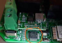
    >>21270089 I Think it is the MCU, see picture. Close-up of a circuit board with an integrated circuit labeled 8H3K64S2.
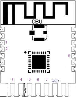
    If I can connect it to the CBU module, it would be fine for me (just have to find out how to be safe with 230V input - maybe opto-coupler with 230V line detection. Something like that: AliExpress 230V Optocoupler module). Can I use any of the CBU-pins that are not connected to the mainboard? There are 14 pins without visible connection. Those would be:

    Pin 3 - P20, Common GPIO (Pin 20 of the IC)
    Pin 4 - P22, Common GPIO (Pin 18 of the IC)
    Pin 5 - P23, ADC (Pin 17 of the IC)
    Pin 6 - P1, UART RX2 (Pin 28 of the IC)
    Pin 7 - P0, UART TX2 (Pin 29 of the IC)
    Pin 8 - P8, IO with PWM hardware support (Pin 24 of the IC)
    PIN 9 - P7, IO with PWM hardware support (Pin 23 of the IC)
    Pin 10 - P6, IO with PWM hardware support (Pin 22 of the IC)
    Pin 11 - P26, IO with PWM hardware support (Pin 15 of the IC)
    Pin 12 - P24, IO with PWM hardware support (Pin 16 of the IC)
    Pin 17 - P28, Common GPIO (Pin 10 of the IC)
    Pin 19 - P9, Common GPIO (Pin 25 of the IC)
    Pin 20 - P17, Common GPIO, can be reused as SPI_MISO (Pin 14 of the IC)
    Pin 21 - P15, Common GPIO, can be reused as SPI_CS (Pin 13 of the IC)

    The UART Pins are probably not suitable, but the others should be useable.
  • #74 21272301
    p.kaczmarek2
    Moderator Smart Home
    Of course you can use them, but remember, they are 0-3.3V levels, not even 5V, nor bigger. What do you want to do with them?
    Helpful post? Buy me a coffee.
  • #75 21272531
    io2345
    Level 7  
    >>21272301 The inputs will receive the signal of the room thermostats and (as standard function) switch on the relays whenever the thermostat switches on. Remember, that I want to use this device as control center for floor heating valves? With it's help I should be able to supply functions like negative logic for the thermostats in summer (for cooling purpose) or warm-overload the floor heatings screed concrete by one degree when the sun provides electricity for free for the heat pump. ;-)

    Can you give me an example for one channel how to do the input detection by script? Let's say Input 1 (for control of relay 1) should be on Pin 1 of the CBU (Symbol P14, corresponds to Pin 11 of the IC). Signal HIGH on that Pin should switch relay 1 on.
  • Helpful post
    #76 21273718
    p.kaczmarek2
    Moderator Smart Home
    If you have digital input on, let's say, P15, then you just need to set the P15 role to dInput (this will have internal pull up resistor enabled), and set the target channel to the same channel that your relay is using. Then, automatically, HIGH state on P15 will set Relay to HIGH state, and LOW state on P15 will set relay to LOW state.
    If you want to inverse the logic, then change dInput to dInput_n (negated).
    Helpful post? Buy me a coffee.
  • #77 21273887
    io2345
    Level 7  
    Thank you. Wish it were that easy every time :-)

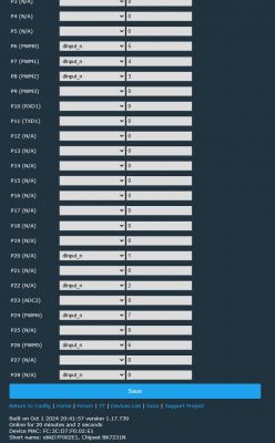
    For those who want to achieve the same. This is what you have to do: First, create an autoexec.bat in Web Application and insert the code shown in Thread 61 ("save, reset SVM and run file..."). Set Config as shown here ("Save"):

    Screenshot of a web application interface configuration with pin settings.

    If you connect now these CBU Pins to GND, the appropriate relais will switch on:

    Diagram of an electronic module with pins labeled CBU and GND.
  • #78 21275094
    io2345
    Level 7  
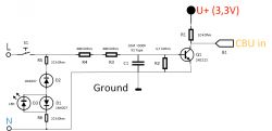
    As there are no important user controls (other than the reset button on the device - don't use it when connected to 230V): once installed in a safe plastic box, you can as well do the 230V input detection the easy way. The chinese devices use a similar method:

    Diagram showing a circuit for detecting 230 V with components like diodes, resistors, and a transistor.

    You will need the same for every input that you want to do 230V detection for.
    R5, R6, D1, D2 and LED are optional, as LED will only show if S1 is switched on or not. R1 and connection to U+ can be skipped, if the input on the CBU has pullup activated, which is true for the config in Thread #77.

    As always when connection to high voltage is present: Be careful, 230V can kill you. Preferably use the optocoupler module mentioned in Thread #73
  • #79 21275589
    p.kaczmarek2
    Moderator Smart Home
    Are you sure about this circuit? Would it also work correctly in case of a voltage spike on L?
    Helpful post? Buy me a coffee.
  • #81 21275597
    p.kaczmarek2
    Moderator Smart Home
    Maybe a varistor could help. Tuya device manufacturers also sometimes put one, but they also often just leave an empty place on PCB for it.
    Helpful post? Buy me a coffee.
  • ADVERTISEMENT
  • #82 21276471
    io2345
    Level 7  
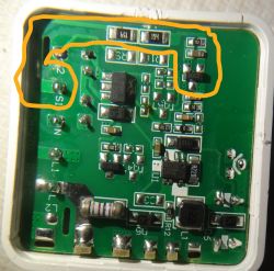
    >>21275592 Can't test it, don't have the necessary components at hand. But I opened a switch I had lying around, and they do very much the same here, only that they are using a MOSFET instead of a bipolar transistor:

    Close-up of a circuit board with electronic components, including resistors and SMD transistors.

    They have R3, R4 at only 150 kOhm, R2 at 7,5 KOhm. Transistor is a 2300 SMD. The capacitor I can't measure (but according to the above link in #80 it should also be 100nF). Doesn't look like X2 at all. Under normal working conditions there shouldn't be more than 10 Volt at the capacitor anyway.
  • #83 21323836
    io2345
    Level 7  
    Is PowerSave working for Chipset BK7231N? No matter if I set nothing, or PowerSave 1 or 2, temperature stays at 47 degrees.
  • #84 21329215
    io2345
    Level 7  
    >>21323836 Or does it have to do something with the communication between CBU and TuyaMCU? Maybe they are talking with each other non-stop? How can I tell?
  • #85 21329223
    DeDaMrAz
    Level 19  
    @io2345

    PowerSave feature is 0 for off and 1 for on, it works on N modules well and 47'C temp is not that much, I would even say it is low.
    Also power save has no meaningful impact on the temp on tuyaMCU devices as you noticed, they need to communicate constantly, more impact is noticed on standalone BK7231 devices.
  • #86 21330580
    p.kaczmarek2
    Moderator Smart Home
    TuyaMCU has to exchange Heartbeat packets all the time, but I don't think it affects power usage much. There are other things that affects power save, for example, PowerSave will not work good if you keep your Web App Logs tab open in the browser.
    Helpful post? Buy me a coffee.
  • #87 21330716
    io2345
    Level 7  
    >>21330580 Of course, Webpage isn't open constantly. Temperature just made me think if it's normal, compared to other devices I have - like a smart plug with LN882H chipset, which is at 31 degrees (with PowerSave 1).
  • #88 21422892
    io2345
    Level 7  
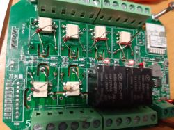
    Pimped version with MOSFET relays instead of mechanical ones (I use only 6 channels). No significant power usage and noiseless.

    Close-up of an electronic circuit board with components, including MOSFET relays and screw terminals.

    As you can see, I also stripped off the RC-part, as I have no use for that.

    Idea was born here: Link
  • #89 21422925
    p.kaczmarek2
    Moderator Smart Home
    What is the maximum power for each channel now?
    Helpful post? Buy me a coffee.
  • #90 21422968
    io2345
    Level 7  
    >>21422925 With this version of "relay" (Omron G3VM-601EY) you can switch 23 watts (100 mA).
    Omron G3VM-601CR/FR would allow up to 140 watts.

Topic summary

The discussion revolves around the LLXLJY 8-channel smart Tuya switch and its compatibility with OpenBK7231T (OBK) firmware. Users share experiences regarding the device's firmware, specifically the BK7231N and BK7231M chipsets, and the challenges faced during firmware backup and flashing. The device is identified as a TuyaMCU, and users discuss methods for capturing packets and controlling the relays through the Tuya app and OBK. Various functionalities, such as relay toggling, interlocking, and remote control pairing, are explored. Users also address issues with initial state settings and the need for proper configuration to ensure reliable operation. The conversation includes technical details about command structures, baud rates, and the importance of understanding device data points (dpIDs) for effective control.
Summary generated by the language model.
ADVERTISEMENT