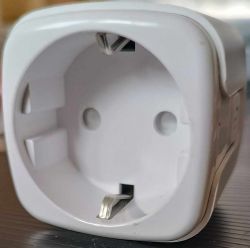
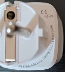
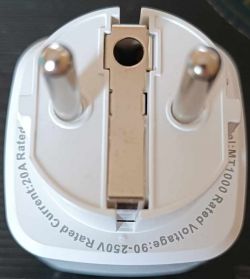
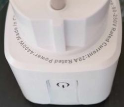
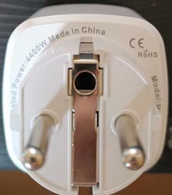
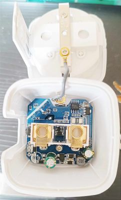
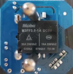
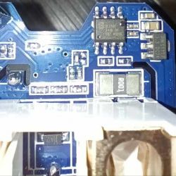
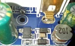
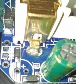
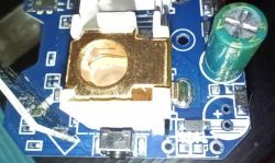
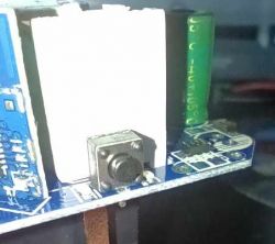
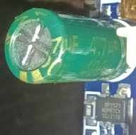
Here I show you the teardown of just another LSPA9 housing.
I opened it with my door of course 😂
https://www.elektroda.com/rtvforum/topic4052105.html
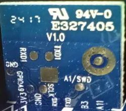
After I de-soldered the sub PCB I can connect some thin wires to the connection points I need to flash the device.
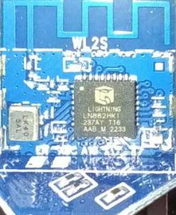
The sub PCB is the new one WL2S with the Wi-Fi chip LN882H.
This chip needs to flash a permanent ground connection at the pin A9, you can also find this point for soldering on the sub PCB.
The following description to flash this chip works very well.
https://www.elektroda.com/rtvforum/topic4028087.html
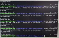
Used the described tool to flash the device with my Windows machine.
https://www.elektroda.com/rtvforum/download.php?id=1205991
But I need to screw down the serial speed to get a working connection.
LN882H_CMD_Tool.exe COMx download flash 921000 0x0 flashimage.bin
Here is a working configuration for the pins:
"3": "Btn;0",
"7": "BL0937CF1;0",
"10": "Rel_n;1",
"11": "Rel;0",
"12": "BL0937CF;0",
"19": "BL0937SEL;0"
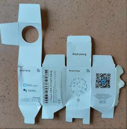
Pin 10 normally is used and configured as the Wi-Fi LED.


