logo elektroda
logo elektroda
X
logo elektroda

Flashing Issues with LSC Light Bulbs Model 2578539.2 Using BK7231 UART Flasher

mattistiret1 1983 35
ADVERTISEMENT
  • #1 21244045
    mattistiret1
    Level 2  
    Hey guys, I just bought 3 LSC light bulbs and honestly, I didn't check the reference.
    So that's the 2578539.2 model, firmware 1.5.32

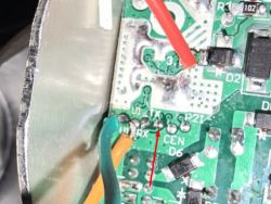
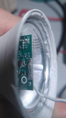
    For some reason I can't flash it with bk7231 easy uart flasher. (Getting bus failed) Close-up of LSC lamp circuit board with connected wires.
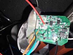
    Anyone have encountered this problem?
    My uart converter is working properly with some other device but not this model.
    Seems like there is no power going to the chip?
  • ADVERTISEMENT
  • #2 21244226
    p.kaczmarek2
    Moderator Smart Home
    Maybe wrong pins? Isn't U1_TX where I pointed the arrow?
    Close-up of a PCB with connected wires and pin labels, including U1_TX indicated by an arrow.
    Helpful post? Buy me a coffee.
  • #3 21244231
    mattistiret1
    Level 2  
    I'll try that soon and let you know :)
  • ADVERTISEMENT
  • #4 21244235
    p.kaczmarek2
    Moderator Smart Home
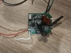
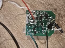
    How it looks from the other side? Maybe we can look at the traces to double check which are UART1.
    Helpful post? Buy me a coffee.
  • #5 21244245
    mattistiret1
    Level 2  
    Circuit board with capacitors and wires on a wooden table Close-up image of a circuit board with various electronic components and connected wires.
    There you go :)

    Added after 47 [minutes]:

    That doesn't work either
  • Helpful post
    #6 21287571
    plekke
    Level 4  
    >>21244245

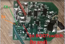
    check my schematic, what worked very good
    https://i.imgur.co Close-up of a circuit board with labeled wires: RX, TX, and BOOTswitch to GND. m/999GUqv.png

    Added after 19 [minutes]:

    esphome: name: lscrgbcct friendly_name: LscRGBCCT
    bk72xx: board: generic-bk7231n-qfn32-tuyathis is my header

    esphome:
    name: lscrgbcct
    friendly_name: LscRGBCCT

    bk72xx:
    board: generic-bk7231n-qfn32-tuya
    wrote:
    
    and this code; https://devices.esphome.io/devices/LSC-Light-White-and-Color-Ambiance-2578539
    cos there is a bp5758d leddriver inside
  • #7 21297674
    mattistiret1
    Level 2  
    >>21287571
    Hi! This wiring is working but, I had to unplug the 3.3V cable.
    I'm not powering it to flash them and it works like a charm

    The pinout you gave me isn't working by the way here is what I got from reading the config from tuya firmware (also not working) :

    Code: JSON
    Log in, to see the code
  • #8 21298130
    plekke
    Level 4  
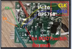
    Image of a circuit board with labeled RX, TX pins and i²c connection to the BP5768 chip.

    indeed, the chip is BP5768, and the esphome library is written for BP5758

    i also did not find the difference in i²c protocols....

    on the bk-chip, i²c clk is pin 24, and i²c data is pin 26

    i added the pinout in the image
  • #9 21305812
    p.kaczmarek2
    Moderator Smart Home
    Is there any documentation of BP5768 protocol? I can add BP5768 support to OBK if it's needed.

    I've only found that, a very short chinese datasheet:
    Helpful post? Buy me a coffee.
  • #10 21305839
    mattistiret1
    Level 2  
    Hi everyone

    So I had to read the pinout from another bulb. I copied this pinout to all the other bulbs (same ones) and now it works like a charm :)
  • #11 21305855
    plekke
    Level 4  
    >>21305839

    hello, what do u mean?

    i traced out the pcb, and had: i²c clk is pin 24, and i²c data is pin 26
  • ADVERTISEMENT
  • #12 21305858
    mattistiret1
    Level 2  
    Using been writer software, I read the pinout and copied it to the bulb once I flashed openbeken
  • #13 21412670
    spicydiet_0o
    Level 1  
    It's been a while, but have you been able to secure the firmware? I'd like to use cloud cutter for the lights, but I need to create a profile...
  • #14 21425311
    gehaxelt
    Level 6  
    Hi there,

    just got one of these bulbs, too (article no: 2578539.2). Managed to dump the firmware and extract the config with bk7231tools:

    
    {
       "2235ccur": 14,
       "2235wcur": 6,
       "Jsonver": "1.1.9",
       "brightmax": 100,
       "brightmin": 5,
       "cagt": 20,
       "category": "0505",
       "cmod": "rgbcw",
       "colormax": 100,
       "colormin": 10,
       "colorpfun": 1,
       "crc": 72,
       "cwmaxp": 100,
       "cwtype": 0,
       "defbright": 100,
       "defcolor": "c",
       "deftemp": 100,
       "dmod": 8,
       "gmkb": 60,
       "gmkg": 60,
       "gmkr": 80,
       "gmwb": 75,
       "gmwg": 70,
       "gmwr": 100,
       "iicb": 0,
       "iicc": 4,
       "iicg": 1,
       "iicr": 2,
       "iicscl": 24,
       "iicsda": 9,
       "iicw": 3,
       "module": "CBU",
       "notdisturb": 0,
       "onoffmode": 1,
       "pairt": 600,
       "pmemory": 1,
       "prodagain": 0,
       "remdmode": 1,
       "rgbt": 15,
       "rstbr": 50,
       "rstcor": "c",
       "rstnum": 5,
       "rsttemp": 100,
       "title20": 1,
       "wfcfg": "spcl",
       "wfct": 10,
       "wt": 20
    }


    Unfortunately, after importing it through the Web UI, it does not appear to work (bulb does not turn on):

    
    ClearIO // clear old GPIO/channels
    lfs_format // clear LFS
    StartupCommand ""  // clear STARTUP
    stopDriver *  // kill drivers
    startDriver SM2235 // so we have led_map available
    setPinRole 9 SM2235DAT
    setPinRole 24 SM2235CLK
    LED_Map 2 1 0 4 3 


    Any ideas what to do?

    EDIT: The chip on the LED-pane is a "BP5768D", so maybe the detected driver "SM2235" is not correct? Using the GPIO-Finder and setting all pins (relay-mode) to high won't light up the bulb at all. How can I help debug?
  • #15 21425341
    divadiow
    Level 34  
    Please post your Tuya firmware backup
  • ADVERTISEMENT
  • #17 21425551
    divadiow
    Level 34  
    try importing this then rebooting

    Code: JSON
    Log in, to see the code
  • #18 21426444
    gehaxelt
    Level 6  
    Thank you, but this does seem to change anything. I tried your and the 9/24 pin configuration, but no luck.

    I'll try to take pictures of the PCB traces and maybe reflash the original firmware to see if I accidentally broke something.... or are there other things I can do?
  • #19 21426480
    p.kaczmarek2
    Moderator Smart Home
    Do you reboot after setting config? Can you see the LED driver running on the main page?

    Please provide some photos of the PCB.
    Helpful post? Buy me a coffee.
  • #20 21426524
    gehaxelt
    Level 6  
    Yes, I issued a "reboot" through the Web UI button. I have just retested using physical power on/off reboots, but no change.

    EDIT: Yes, the driver(s) are running according to the main page. My assumption was that maybe the wrong pins/channels are set?

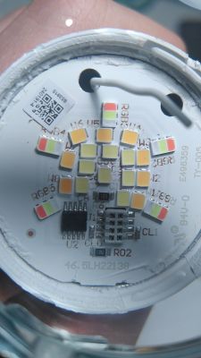
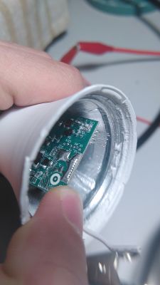
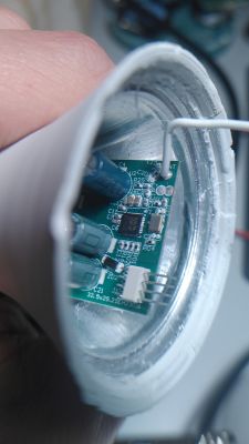
    Here are the images of the PCB:

    Close-up of a circuit board with multicolored LEDs and two wires connected at the top.
    Person holding a circuit board inside a white cylindrical casing.
    Close-up of a circuit board inside a casing with visible capacitors and a connector.
    Close-up of a circuit board with visible electronic components and pins.
  • #21 21426598
    divadiow
    Level 34  
    OK. I see where 9, 24 comes from

    Code: JSON
    Log in, to see the code


    so re-reading past experiences above it seems @Matistreet got their 2578539.2 with BP5768D working fully? in OBK?

    Yours is a 2576539.2 with BP5768D so the expectation is that the OBK BP5758D driver is OK on BP5768D.

    Added after 14 [minutes]:

    >>21412670

    @spicydiet_0o if your device is the 2578539.2 with firmware version 1.5.2, the same posted here https://www.elektroda.com/rtvforum/topic4078301.html#21425425

    then a cloudcutter profile will not be possible. 1.5.2 / 3.3.42 BUILD AT:2023_09_05_15_44_43 is on the known patched list https://github.com/tuya-cloudcutter/tuya-cloudcutter/wiki/Known-Patched-Firmware
  • #22 21426635
    gehaxelt
    Level 6  
    Quote:
    so re-reading past experiences above it seems @Matistreet got their 2578539.2 with BP5768D working fully? in OBK?
    Yours is a 2576539.2 with BP5768D so the expectation is that the OBK BP5758D driver is OK on BP5768D.


    Double checked the numbers again and found a mistake. I have a 2578539.2 as well, sorry. So yes, I would expect it to work, too, but it won't right now.
  • #23 21426640
    divadiow
    Level 34  
    ah OK, sure. Maybe flash back to factory to be sure?

    Added after 14 [minutes]:

    interesting (maybe) that there's mention of kp18058 and sm2135 in your firmware but no mention of bp57xx

    Added after 5 [minutes]:

    could try kp18058 driver just in case?
  • #24 21426783
    gehaxelt
    Level 6  
    You're totally right (had a look at the app.bin, too), but it still does not work. How reliable is the GPIO pin extraction? Could it be that I'm configuring the wrong pins? Setting all pins to HIGH in the web UI does not result in the bulb lighting up. I'll reflash the original firmware on the weekend...

    Thanks for all the help so far :)
  • #25 21426794
    p.kaczmarek2
    Moderator Smart Home
    Do you reboot after every pin change, so the driver starts with new config?
    gehaxelt wrote:
    Setting all pins to HIGH in the web UI does not result in the bulb lighting up.

    The so-called I2C drivers will not light up LED if you set all pins to High. It's not PWM - it requires a transaction that follows a specific protocol.
    Helpful post? Buy me a coffee.
  • #26 21426815
    gehaxelt
    Level 6  
    Ah, alright - understood! I thought I did "reboot" the whole device with the big red button for every test, but I'll redo them again just in case I overlooked something.

    Let's assume I flash the original image - can I somehow verify the pin settings with a multimeter or would I need an oscilloscope (which I don't have)?
  • #27 21426893
    divadiow
    Level 34  
    interesting observation, new to me anyway, https://github.com/search?q=bp5768d&type=code - BP57X8D seem to be grouped so I guess the same driver can be used, as evidenced by the experience of the OP

    Added after 1 [minutes]:

    gehaxelt wrote:
    can I somehow verify the pin settings with a multimeter or would I need an oscilloscope (which I don't have)?


    continuity with the multi-meter even before flashing to factory?
  • #28 21428292
    gehaxelt
    Level 6  
    Hi again, spent a bit of time trying to flash back the original firmware. Is there a trick to it with openbeken already flashed? It seems like I can't get the chip into flash mode (power on/off or cen methods) - it just boots into openbeken? Can I flash the full original dump from the web UI?
  • #29 21428585
    p.kaczmarek2
    Moderator Smart Home
    It should just work as usual. You can reboot even without CEN, just through OBK restart button.
    Helpful post? Buy me a coffee.
  • #30 21431966
    gehaxelt
    Level 6  
    You were right and I have some good news! Using my little DSO138 oscilloscope, I managed to identify the PINs used in the original firmware. These correspond to Pin 7 + 8 in OBK, so with a bit of trial and error I identified the right configuration to make this light bulb work:

    
    ClearIO // clear old GPIO/channels
    lfs_format // clear LFS
    StartupCommand ""  // clear STARTUP
    stopDriver *  // kill drivers
    startDriver BP5758D // so we have led_map available
    setPinRole 7 BP5758D_DAT
    setPinRole 8 BP5758D_CLK
    //BP5758D_Current 14 6 // according to the extractor, but I use lower values for less heat
    BP5758D_Current 10 5
    BP5758D_Map 0 1 2 3 4 


    Here's my importable config:

    
    {
      "vendor": "Action",
      "bDetailed": "0",
      "name": "LSC Smart Connect LED Smart Lightbulb A60 E27 RGB (WiFi)",
      "model": "ArtNo. 2578539.2",
      "chip": "BK7231N",
      "board": "CBU",
      "flags": "1024",
      "keywords": [
        "Action LCS",
        "Lightbulb",
        "BK7231N",
        "CBU",
        "OpenBeken"
      ],
      "pins": {
        "7": "BP5758D_DAT;0",
        "8": "BP5758D_CLK;0"
      },
      "command": "backlog BP5758D_Current 14 6; BP5758D_Map 0 1 2 3 4; Dimmer 50;",
      "image": "https://obrazki.elektroda.pl/8091289800_1738784599.jpg",
      "wiki": "https://www.elektroda.com/rtvforum/topic4078301.html"
    }


    The LED map had also to be changed. Can we somehow fix the bktools extractor to find the correct driver and pins?

Topic summary

The discussion addresses flashing issues with LSC Light Bulbs model 2578539.2 using the BK7231 UART flasher, where users encountered "bus failed" errors and suspected incorrect UART pin connections or lack of power to the chip. Initial attempts to flash using default pinouts (e.g., pins 9 and 24 for I²C) failed. Investigation revealed the bulb uses a BP5768 LED driver chip, differing from the BP5758 driver supported by existing esphome libraries. Successful flashing was achieved by identifying the correct UART and I²C pins (notably pins 7 and 8 for BP5758D data and clock lines) through oscilloscope measurements and pin extraction from a working bulb. Users shared configurations and importable OBK (OpenBeken) driver settings, emphasizing the need to stop old drivers, clear GPIO roles, and assign correct pin roles for BP5758D. Firmware dumps and Tuya configuration extractions showed discrepancies between documented and actual pin assignments, suggesting factory changes or legacy config remnants. Attempts to flash back original firmware using OpenBeken were discussed, with advice to reboot after config changes and verify driver operation via web UI. The community noted that some firmware versions (e.g., 1.5.2) are patched, preventing cloudcutter profile creation. Overall, the solution involved manual pin discovery, correct driver selection (BP5758D for BP5768 chip), and proper OBK configuration to enable flashing and control of the LSC 2578539.2 bulbs.
Summary generated by the language model.
ADVERTISEMENT