First time playing with flash. Bulb with action, none of the configurations fit. The bulb has been present in at least 3 revisions. One of the forums had identical packaging but on the BP module. Tuya cloud-cutter does not work due to version 1.5.21.
I disassemble the bulb, remove the cover with a knife, then glue it around the LED board and take it out. Access to the pins is sufficient without further disassembly as in the photos. Pins RX1, TX1 are available without desoldering the element. We solder and connect, I used cp2102. We download BK7231GUIFlashTool and make a backup, and then flash OpenBK7231T_App. During the module reset message, I disconnected the pin from ground and it went away.
Experience acquired, always check the controller. It turned out that I had KP18068 and not like other BP revisions... but the KP18058 driver works correctly. The color mapping still needs to be improved and you need to create a startDriver:
Below are the photos and the ready json for import.
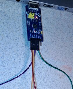
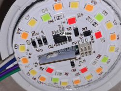
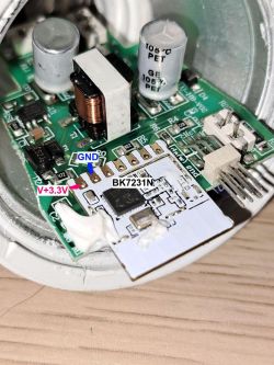
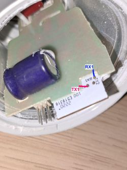
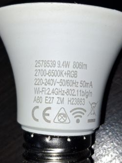
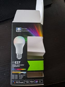
I disassemble the bulb, remove the cover with a knife, then glue it around the LED board and take it out. Access to the pins is sufficient without further disassembly as in the photos. Pins RX1, TX1 are available without desoldering the element. We solder and connect, I used cp2102. We download BK7231GUIFlashTool and make a backup, and then flash OpenBK7231T_App. During the module reset message, I disconnected the pin from ground and it went away.
Experience acquired, always check the controller. It turned out that I had KP18068 and not like other BP revisions... but the KP18058 driver works correctly. The color mapping still needs to be improved and you need to create a startDriver:
startDriver KP18058
KP18058_Map 1 2 0 4 3
Below are the photos and the ready json for import.
{
  "vendor": "LSC",
  "bDetailed": "0",
  "name": "LSC LED Smart white and color ambiance E27 9.4W 806lm 2578539",
  "chip": "BK7231N",
  "board": "on pcb",
  "flags": "0",
  "keywords": [
    "RGBCW",
    "LED",
    "Action",
    "E27",
    "bulb",
    "KP18068",
    "CB2L"
  ],
  "pins": {
    "7": "KP18058_CLK;1",
    "8": "KP18058_DAT;0"
  },
  "command": "\"backlog startDriver KP18058; KP18058_Map 1 2 0 4 3\"",
  "image": "https://obrazki.elektroda.pl/7583804800_1712132196_thumb.jpg",
  "wiki": "https://www.elektroda.com/rtvforum/topic4046526.html"
}


Cool? Ranking DIY


