 .
.
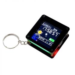
This inconspicuous module is based on the ESP32 C3 and offers a 1.44" colour display with 128x128 resolution, controlled via SPI protocol. Here I will show how easy it is to get started with it, how it can be batch uploaded remotely (via WiFi), how to display a simple animation and compare the display speed between software and hardware SPI. In addition, I will check if an older esptool can handle the ESP32-C3....
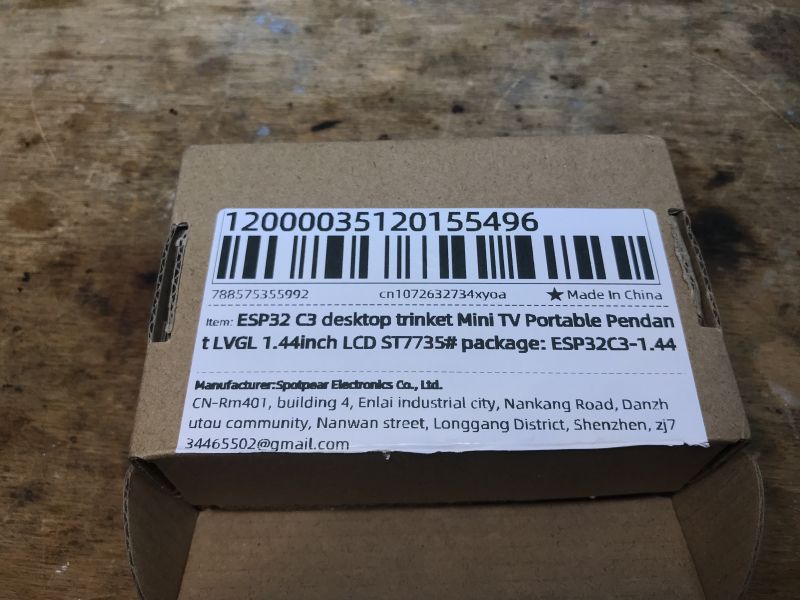
The product often appears under the heading 'ESP32 C3 Desktop Trinket Mini TV Portable Pendant LVGL 1.44inch LCD ST7735' and can be purchased for around £40. I received the whole thing after purchase in such a box, properly protected:
 .
.
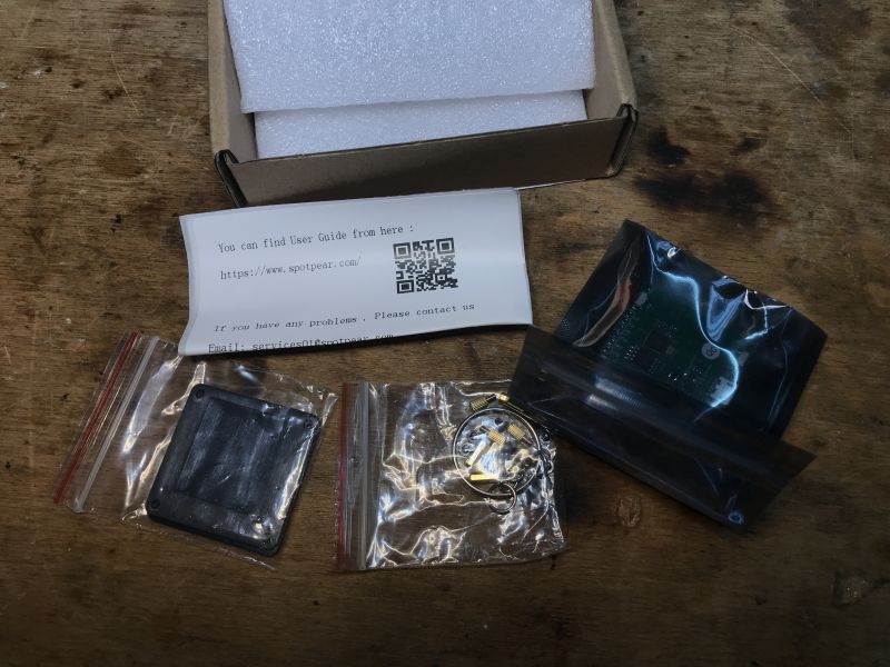
Also included is a simple case based on spacers and a key fob:
 .
.
The attached sticker (why sticker?) with QR code refers us to information from the vendor .
 .
.
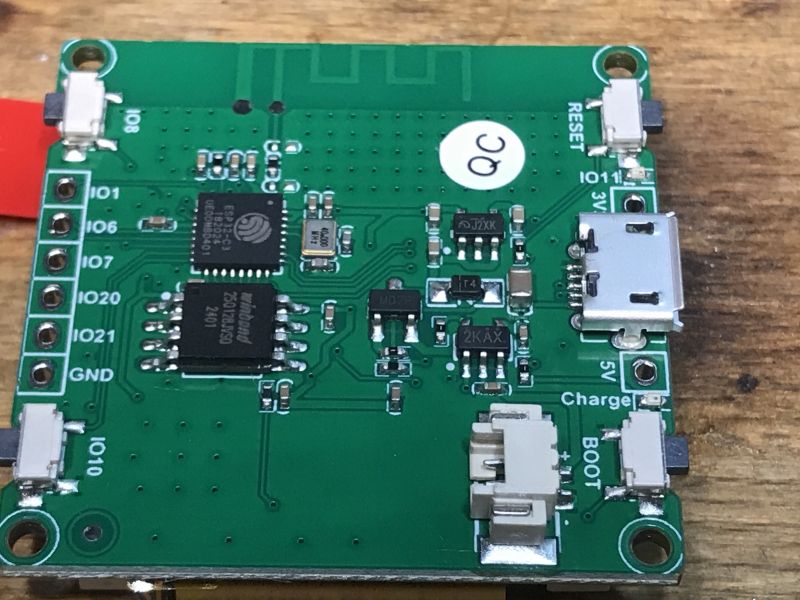
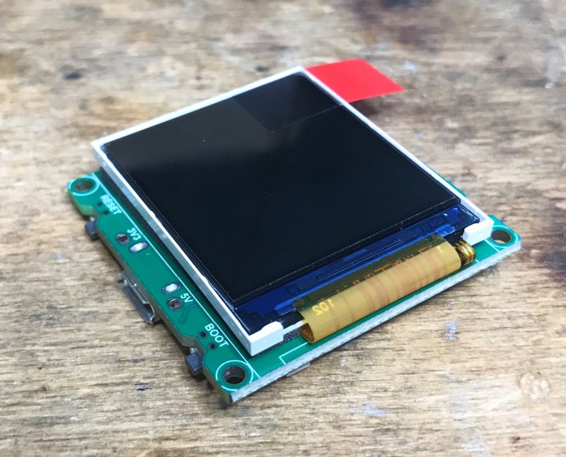
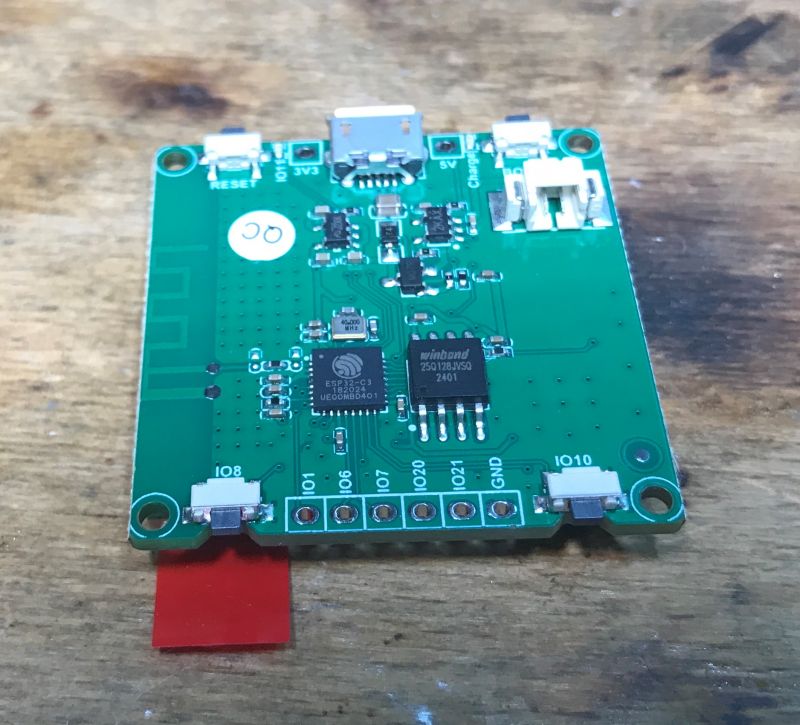
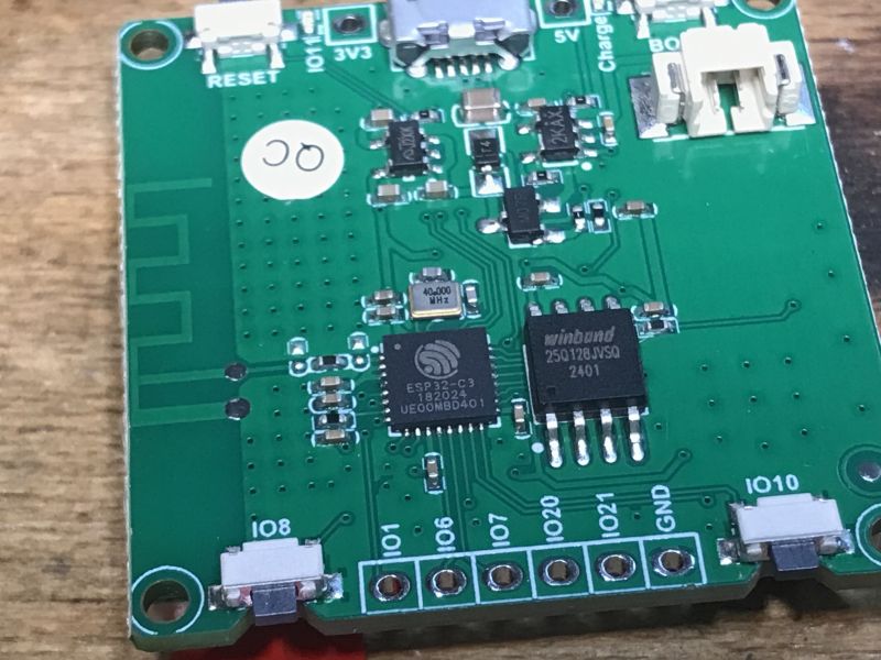
And here is the module itself:
 .
.
In addition to the classic BOOT (bootloader mode) and RESET buttons, here we also have two additional buttons on IO8 and IO10, as well as having pads from several pinouts.
You can see the 25Q128JVSG memory (all 16MB of it) and of course the ESP32-C3. There is also a 1.27mm connector for connecting a Li-Ion cell and a micro USB connector.
Information from the vendor leads to a short tutorial/documentation at:
https://spotpear.com/wiki/ESP32-C3-desktop-tr...ortable-Pendant-LVGL-1.44inch-LCD-ST7735.html
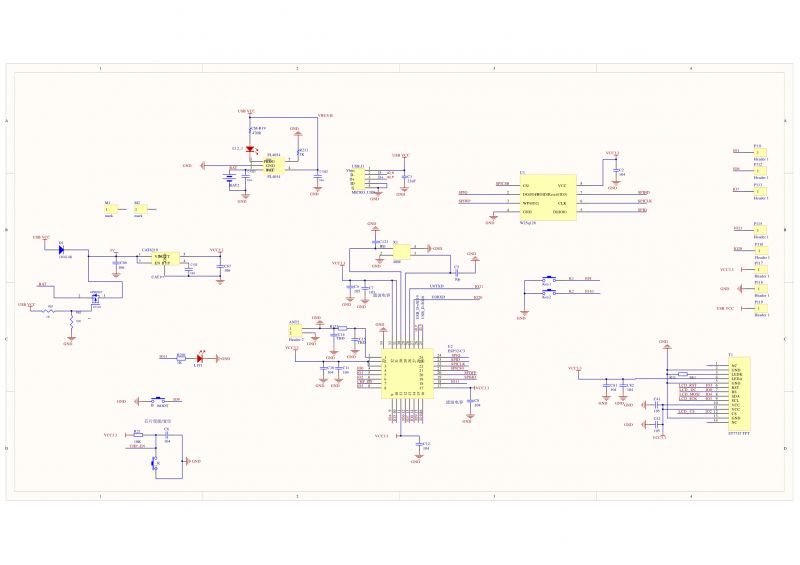
Diagram:
 .
.
Li-Ion battery support is handled here by the PL4054. 3.3V (with 5V from USB) is provided by the CAT6219. Flash memory is, as mentioned, the W25Q128, and the display.... you know
Demonstration program .
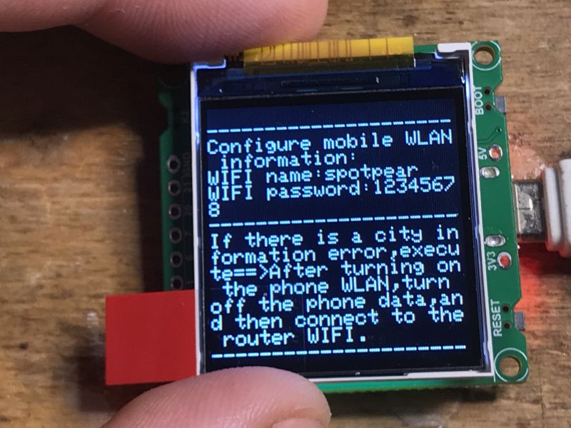
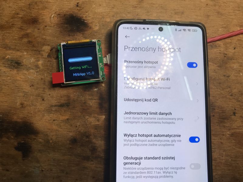
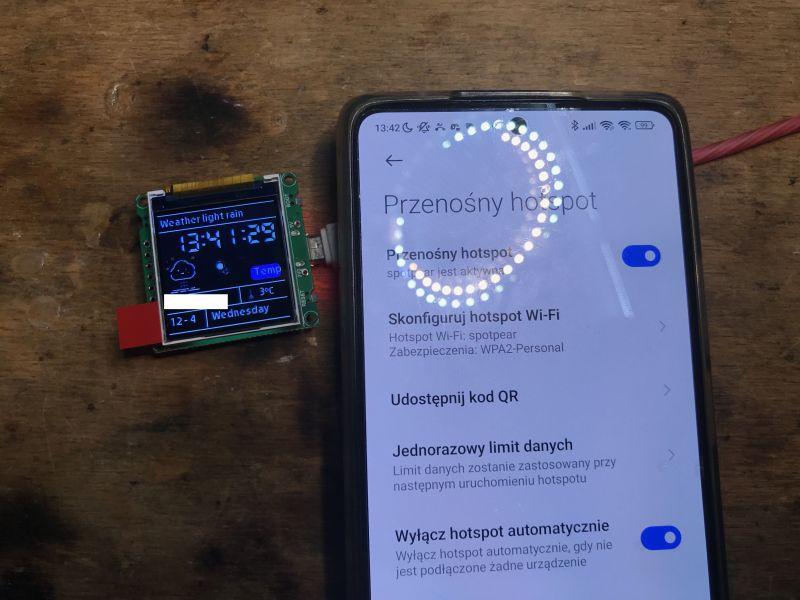
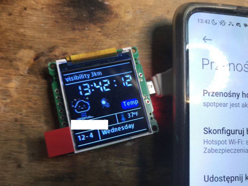
The demonstration program is pre-loaded on the board and displays the image as soon as power is applied:
 .
.
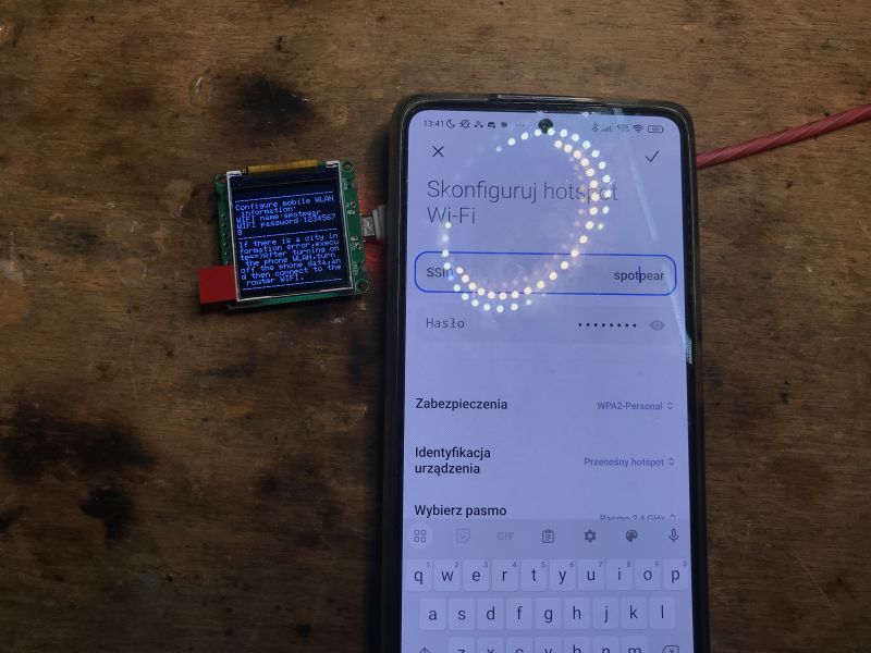
I couldn't find an English-language manual for its use on the web, but basically it just requires a WiFi access point to be set up on our phone with the data:
spotpear
12345678
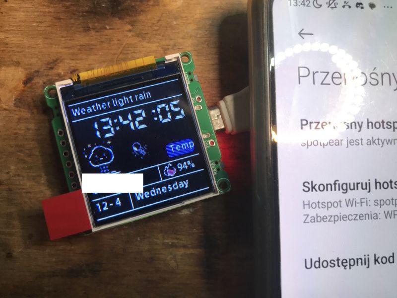
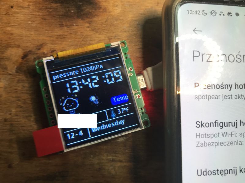
It then connects to it and then downloads weather information for our location via our phone's internet connection:
 .
.
The top bar successively displays the downloaded data.
 .
.
The program source can be downloaded on Github:
https://github.com/Spotpear/ESP32C3_1.44inch
Flash copy and error Unexpected CHIP magic value 0x1b31506f .
To start with I started by making a copy of the original factory program and by then I had already encountered the problem. I used my tried-and-tested esptool.py, which I installed once along with the ESP support for Arduino:
esptool.py read_flash 0 0x1000000 ESP32-C3-Desktop-Trinket-Mini-TV-Portable-Pendant-LVGL-1.44inch-LCD-ST7735.bin
pause
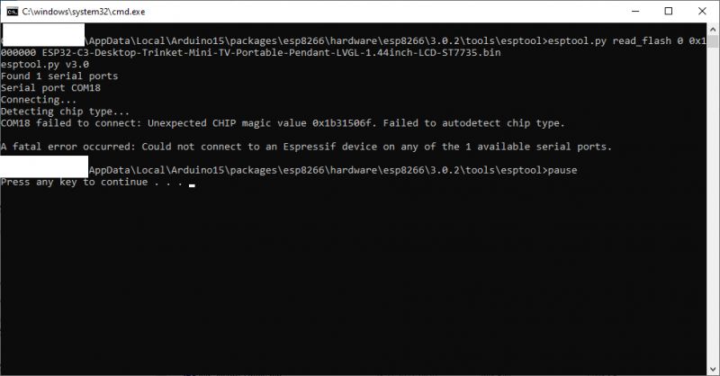
However, this esptool does not recognise this board:
 .
.
This is because it is version 3.0.2, as indicated by the path itself:
esp8266\hardware\esp8266\3.0.2\tools\esptool
Therefore, it is better to download the latest esptool from Github - you can already in exe form:
https://github.com/espressif/esptool/releases
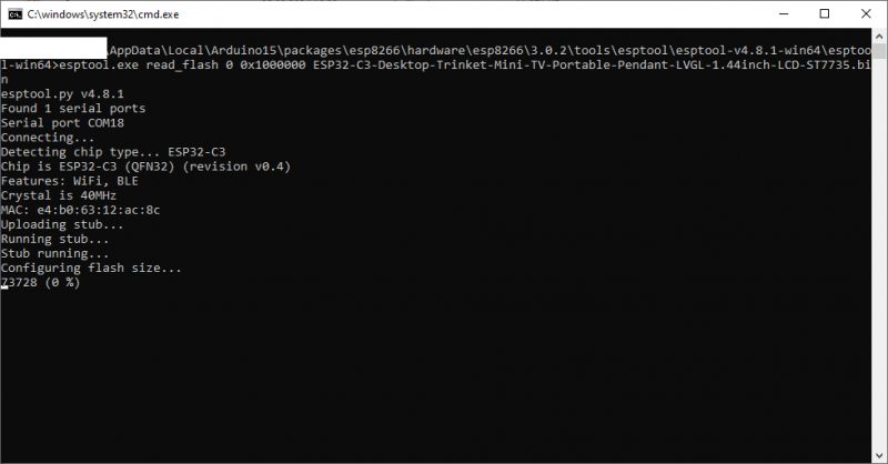
The newer esptool-v4.8.1-win64.zip was able to rip the batch without any problems .
 .
.
esptool.exe read_flash 0 0x1000000 ESP32-C3-Desktop-Trinket-Mini-TV-Portable-Pendant-LVGL-1.44inch-LCD-ST7735.bin
pause
I have posted a copy here:
https://github.com/openshwprojects/FlashDumps/tree/main/IoT/ESP32
Easiest program in PlatformIO .
Some people still program in the Arduino IDE, but I find it easier in PlatformIO. This environment is an add-on to the free Visual Code, which I have described more extensively in earlier topics:
How to program a Wemos D1 (ESP8266) board in Arduino shape? ArduinoOTA in PlatformIO .
Clock on ESP12 and MAX7219 display - tutorial - part 1, ArduinoOTA, basics .
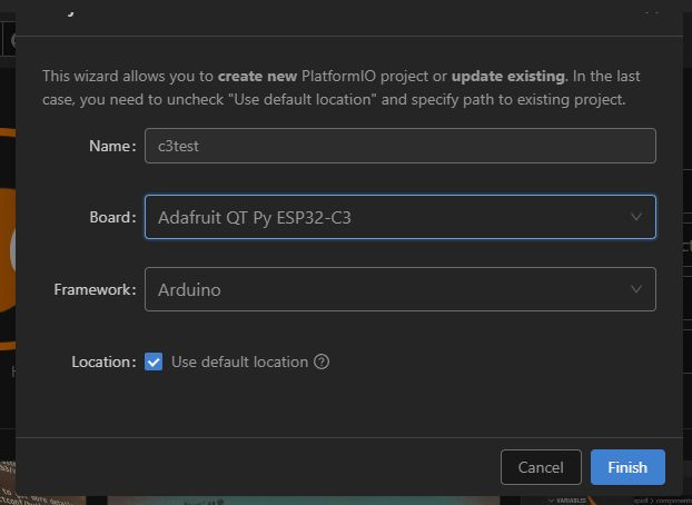
I have created a new project. I couldn't find this particular one from the topic in the boards, so I used another one from ESP32-C3.
 .
.
To start, I ran the UART alone, without the display.
Code: C / C++
My platformio.ini
[env:adafruit_qtpy_esp32c3]
platform = espressif32
board = adafruit_qtpy_esp32c3
framework = arduino
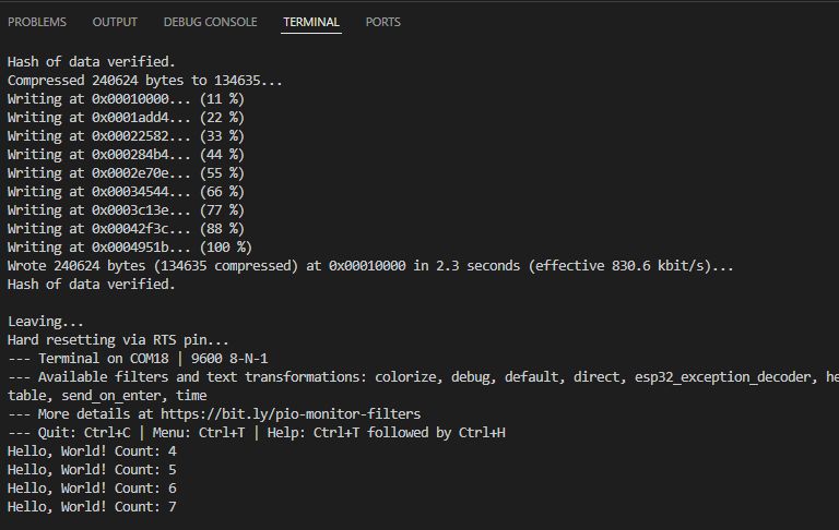
One call to "Upload and Monitor" later, everything started working as expected:
 .
.
We are running the display in PlatformIO .
Ok, but we didn't buy this board to not use its display. It needs to be made operational.
You will need two libraries for this:
- adafruit/Adafruit ST7735 and ST7789 Library .
- adafruit/Adafruit GFX Library .
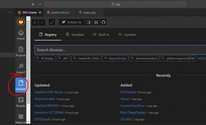
These can be added via the PlatformIO GUI:
 .
.
... or simply add them to our platformio.ini and PIO will download them itself:
[env:adafruit_qtpy_esp32c3]
platform = espressif32
board = adafruit_qtpy_esp32c3
framework = arduino
lib_deps =
    adafruit/Adafruit ST7735 and ST7789 Library
    adafruit/Adafruit GFX Library
Then we can start Hello World ST7735. Here it is important to set the pin indices appropriately, as they may differ between modules:
Code: C / C++
Here we have in sequence:
- Adafruit_ST7735(int8_t cs, int8_t dc, int8_t mosi, int8_t sclk, int8_t rst) - runs the display in software SPI mode (bit-bang).
- tft.initR(INITR_BLACKTAB) - initializes display with appropriate configuration for ST7735
- tft.fillScreen(color) - fills the entire screen with the specified colour
- tft.setCursor(x, y) - sets the cursor position
- tft.setTextColor(color) - sets text colour
- tft.setTextSize(size) - sets text size
- tft.print(text) - displays the text at the current cursor position
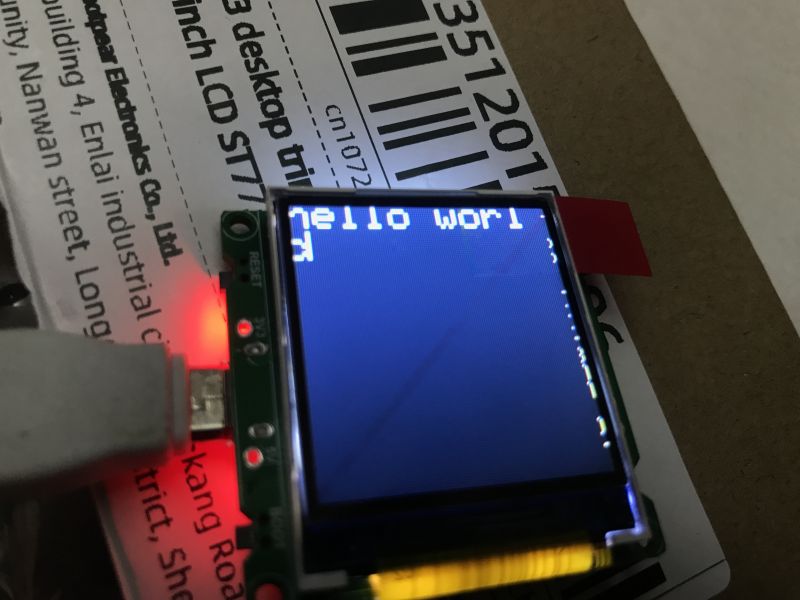
Result:
 .
.
Animation and partial screen cleaning technique .
Static text is not everything - it is possible to do quite smooth animations here. Of course, this requires appropriate optimisation, one of which is to draw only what has changed on the screen.
For example, when we want to draw a simple clock, instead of refreshing the whole screen with each movement of the hand, we can simply 'blur' the previous hand with the background colour and then draw it again:
Code: C / C++
Not much has changed in the code, basically I just count the centre of the screen at the beginning and then in the function from drawing the pointer I also count the tip of the pointer for a given angle (from trigonometry). I connect the centre point with the calculated tip with a line. I call the same thing twice in the loop, once for the "old" pointer, painting it with the background colour, and then for the "new" pointer - in white.
The result:
Updating the batch over the network .
Let's not forget the Arduino OTA - I've already presented it here, among others:
How to program a Wemos D1 (ESP8266) board in the shape of an Arduino? ArduinoOTA in PlatformIO .
Let's modify my project to add a remote update. New PlatformIO.ini:
[env:adafruit_qtpy_esp32c3]
platform = espressif32
board = adafruit_qtpy_esp32c3
framework = arduino
lib_deps =
    adafruit/Adafruit ST7735 and ST7789 Library
    adafruit/Adafruit GFX Library
    ArduinoOTA

[env:adafruit_qtpy_esp32c3_ota]
extends = env:adafruit_qtpy_esp32c3
upload_protocol = espota
upload_port = 192.168.0.192
New code:
Code: C / C++
The added ArduinoOTA.begin(); initiates the OTA system, and in turn the regular call ArduinoOTA.handle(); that handles the update itself is equally important.
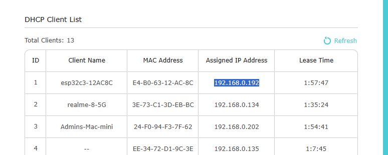
After the first upload, we check the board's IP on the router and enter it into the aforementioned platformio.ini:
 .
.
Now we have two task groups on the sidebar, we start the upload from the OTA group:
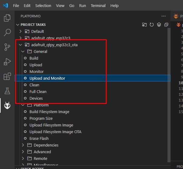 .
.
The programme is updated remotely:
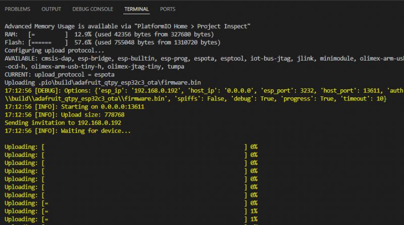 .
.
Colours .
There is a slightly larger selection of colours on this board than I have shown so far. Here is the modified "clock" code, so that the pointer changes colour depending on which quadrant of the screen it is in:
Code: C / C++
The result:
Faster drawing .
So far, I have shown examples in a version based on software-based, free SPI. Such SPI is implemented by software "swiping" the pins, as can be seen in the library code (see TFT_SOFT_SPI section):
Code: C / C++
but the hwspi, or hardware SPI, option is also available.
Which SPI is used depends on the constructor used.
In order to run the hardware SPI, a minor change needs to be made:
Code: C / C++
The rest of the code analogously. Now the question is, how much does this give us?
Let's do a small benchmark for this, a performance test:
Code: C / C++
The code above saves the current time and then fills the screen repeatedly with different colours using the fillScreen function. Then the current time is downloaded again and how much the whole process took is calculated.
I ran it for both versions and compared the results:
Software SPI: 16 014ms
Hardware: 470ms
Hardware SPI is more than 30 times faster in this case. It will definitely make a noticeable difference, especially at frequent screen refresh rates.
Demonstration of various features .
This display can still do a bit more, so I decided to flip the "graphicstest" program from Adafruit over to it:
https://raw.githubusercontent.com/adafruit/Ad...master/examples/graphicstest/graphicstest.ino
The program only required changing the pins and port from the Adafruit_ST7735 class constructor:
Code: C / C++
Result:
Buttons and their operation .
Finally, it is worth showing the use of the buttons on pins IO8 and IO10. In the simplest version, you can use pinMode and the usual digitalRead to operate them. I won't worry about contact vibration here, I will solve the problem by adding a blocking delay in the code. Menu navigation, for example, can be implemented based on these buttons:
Code: C / C++
The above code could be significantly improved, first of all by removing the blocking delay , as well as by optimising the display of the menu - instead of drawing it all over again every time, you could just paint over the arrow and draw it in a new place. The result:
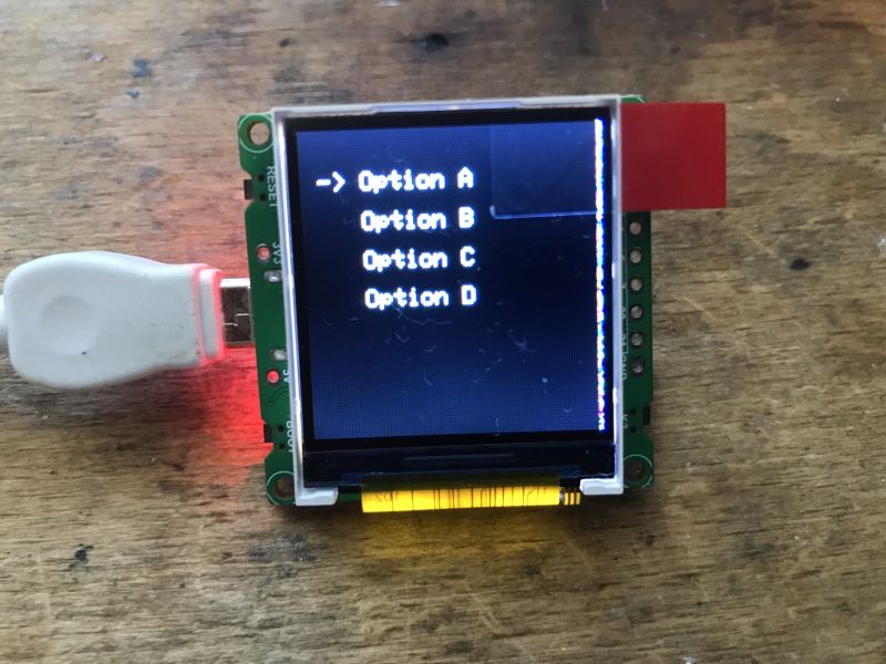
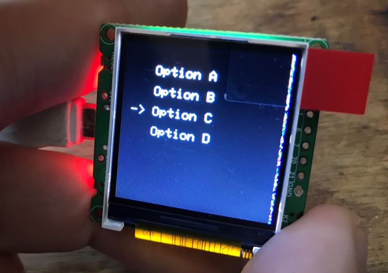 .
.
Much simplified ST7735 support library in one file/project .
Here without much commentary, but maybe someone will find it useful.
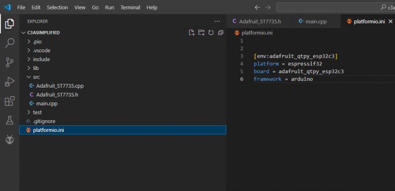
I wanted to get more familiar with the ST7735 support, and I reworked myself a library from Adafruit so that it has just 600 lines of code and in C style (no class). The whole thing only supports software SPI (bit-bang) and can only draw simple shapes, there is no font. Everything is in one PlatformIO project:
 .
.
My simplified demo:
Code: C / C++
Result:
Download: .
.
Summary .
A very interesting module. A bit of design can be done, and there are ready-made libraries for everything. The display can be driven both hardware (efficiently) and software, although the latter option is unlikely to be useful here. Flash memory is plentiful, all 16MB. In addition to the boot and reset buttons, the following are also provided There are two GPIOs, so you can control something without soldering, and if you want additional peripherals, this is also an option.
However, I haven't tested battery power and here I have a doubt: how long will it last with this display on a cell? Is it not too bright? The current consumption of my example with the display is around 70-100mA....
Have you used this module, what applications do you see for it? .
Cool? Ranking DIY Helpful post? Buy me a coffee.


