Here is a config guide for a PIR sensor that is not yet on the LIST.
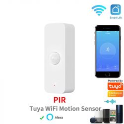
This is the product pic borrowed from the marketplace:
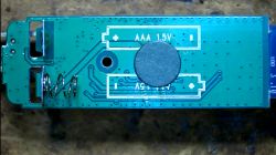
after removing the PCB from the case this is what we find:
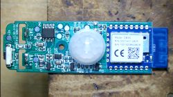
The UART lines (Tx and Rx) we use for programming the CB3S module are shared by the CB3S module and the Tuya chip (the 8 pin SOIC chip at the top left). This means we need to free these pins temporarily. This can be done in a few ways:
1. Remove the SOIC chip temporarily
2. Remove the CB3S module temporarily
3. Break the Rx/Tx lines temporarily
I opted for the first option and removed the SOIC chip with hot air. I also soldered on a few wires to strategically important places:
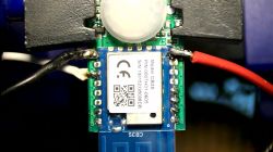
Red: 3.3V, Black: GND, White: Monitor/Debug
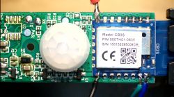
Blue: Tx, Green: Rx. You can also see the SOIC chip removed in the top left corner.
Note: The 3.3V can be connected to the battery terminal, but the GND must be connected directly to the CB3S module, otherwise it will reset every few seconds if you don't press the button every few seconds...
Using the flasher utility is straightforward. Make a backup, then upload the new firmware.
This is the Autoexec.bat file I use (with help of this forum):
No special configuration is needed, just change the MQTT settings and any flags you need and that's it:
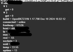
At the end don't forget to remove the temporary wires and reattach the 8 pin SOIC chip.
Finished!
Here is a more detailed guide: https://diy.viktak.com/2025/02/tuya-pir-sensor-conversion-to-open-source-walkthrough.html
This is the product pic borrowed from the marketplace:

after removing the PCB from the case this is what we find:


The UART lines (Tx and Rx) we use for programming the CB3S module are shared by the CB3S module and the Tuya chip (the 8 pin SOIC chip at the top left). This means we need to free these pins temporarily. This can be done in a few ways:
1. Remove the SOIC chip temporarily
2. Remove the CB3S module temporarily
3. Break the Rx/Tx lines temporarily
I opted for the first option and removed the SOIC chip with hot air. I also soldered on a few wires to strategically important places:

Red: 3.3V, Black: GND, White: Monitor/Debug

Blue: Tx, Green: Rx. You can also see the SOIC chip removed in the top left corner.
Note: The 3.3V can be connected to the battery terminal, but the GND must be connected directly to the CB3S module, otherwise it will reset every few seconds if you don't press the button every few seconds...
Using the flasher utility is straightforward. Make a backup, then upload the new firmware.
This is the Autoexec.bat file I use (with help of this forum):
startDriver TuyaMCU
startDriver tmSensor
setChannelType 1 readonly
//Link dpid al canal 1
linkTuyaMCUOutputToChannel 1 val 1
setChannelType 3 readonly
//Link dpid al canal 3
linkTuyaMCUOutputToChannel 3 val 3
SetChannel 1 2
No special configuration is needed, just change the MQTT settings and any flags you need and that's it:

At the end don't forget to remove the temporary wires and reattach the 8 pin SOIC chip.
Finished!
Here is a more detailed guide: https://diy.viktak.com/2025/02/tuya-pir-sensor-conversion-to-open-source-walkthrough.html
Cool? Ranking DIY


