Let me summarize my way to tear IMMAX NEO Smart (bk7231n/cbu) down and to flash it with OpenBK. So, just someone may find it useful in the future and learn from my dead ends i had waled through...
I bough my self this device as i thought i might to connect it with simple DIY CC&CP circuit, so it might make a simple DIY EVSE with wattmeter together. However, I realised it needs cloud to connect to, which showed up to be Tuya cloud. So I decided to tear this device down in order to know what is inside. What a surprise, there is BK7231N in it. This way i get to know there is something like OpenBK, so I decided to flash it.
I tried with hid_download_py on my Macbook first. I did not work for me eventually. Reading and erasing seemed to work somehow, writing always failed. I was not successful varying the baud rates, not even changing the way i was resetting the device to get the bus. I tried also connecting CSN to ground without any success. There is few threads on the net addressing same issues, they all ended up in using https://github.com/openshwprojects/BK7231GUIFlashTool under Windows. BK7231GUIFlashTool worked for me eventually. I was able to flash it with this tool successfully.
Anyway, during the previous attempts the CBU suffered quite lot, so I am not able to tell what actually causes how it afterwards...
After flashing the device, it did not boot, no wifi appeared, nothing was comming from TX2 for debugging. So I almost gave up already when it came to my mind that I screwed up a bootloader somehow with my previous attemps, so I was trying some (maybe really random) steps to recover it.
tl/dr... the sequence which seemed to work for me was
1) Use 'Erase all' button
2) Check 'Overwrite bootloader'
3) Do firmware write - using the latest firmware (which currently is this file https://github.com/openshwprojects/OpenBK7231...wnload/1.17.802/OpenBK7231N_QIO_1.17.802.bin)
After this and (some amount of restarts - will address later) it suddenly appears to be findable as an Wifi access point. ...as a charm. I connected to AP and was able to ,ake some configurations etc.
However... there is one thing i am not able to deal with in any deterministic way and maybe this was actually source of my troubles, not the boot loader actually...
When I connect it to flash tool, I need to initiate the flash reading/writing with short touching CEN to GND. It seems like nothing is needed to be done with CSN. But after successful flashing I am not (in any reliable way) able to force the device to come from the flashing mode to the normal operation mode.
Lastly it worked something like disconnect it from flasher, turn it off, leave it for a minute, turn it on, leave it for the minute and it is up. But this works for me ONLY after full erase and full flash (see above), for the first time. If i connect it to read/write configuration, I am not able to get it out the flashing mode in any possible way. So I ended up in erase, flash, this weird reboot sequence and reconfigure from web. This way it works for me and I am all good now. But still wondering why
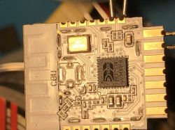
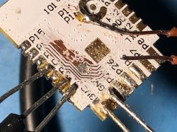
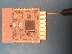
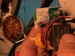
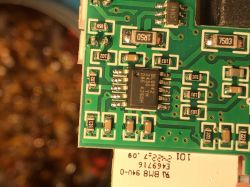
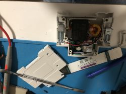
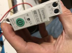
Few pictures from my experience...
AI: Could you specify the exact version of the OpenBK firmware you used for flashing the device?
OpenBK7231N_QIO_1.17.802.bin
AI: Did you notice any error messages or logs during the failed boot attempts that might provide more insight into the issue?
i was not able to get the BK7231N from the flash mode after flashing...
Added after 8 [hours] 23 [minutes]:
so far the device seems to be identical to this one https://www.elektroda.com/rtvforum/topic3990985.html
at least same configuration for leds, button and relay works for me
I bough my self this device as i thought i might to connect it with simple DIY CC&CP circuit, so it might make a simple DIY EVSE with wattmeter together. However, I realised it needs cloud to connect to, which showed up to be Tuya cloud. So I decided to tear this device down in order to know what is inside. What a surprise, there is BK7231N in it. This way i get to know there is something like OpenBK, so I decided to flash it.
I tried with hid_download_py on my Macbook first. I did not work for me eventually. Reading and erasing seemed to work somehow, writing always failed. I was not successful varying the baud rates, not even changing the way i was resetting the device to get the bus. I tried also connecting CSN to ground without any success. There is few threads on the net addressing same issues, they all ended up in using https://github.com/openshwprojects/BK7231GUIFlashTool under Windows. BK7231GUIFlashTool worked for me eventually. I was able to flash it with this tool successfully.
Anyway, during the previous attempts the CBU suffered quite lot, so I am not able to tell what actually causes how it afterwards...
After flashing the device, it did not boot, no wifi appeared, nothing was comming from TX2 for debugging. So I almost gave up already when it came to my mind that I screwed up a bootloader somehow with my previous attemps, so I was trying some (maybe really random) steps to recover it.
tl/dr... the sequence which seemed to work for me was
1) Use 'Erase all' button
2) Check 'Overwrite bootloader'
3) Do firmware write - using the latest firmware (which currently is this file https://github.com/openshwprojects/OpenBK7231...wnload/1.17.802/OpenBK7231N_QIO_1.17.802.bin)
After this and (some amount of restarts - will address later) it suddenly appears to be findable as an Wifi access point. ...as a charm. I connected to AP and was able to ,ake some configurations etc.
However... there is one thing i am not able to deal with in any deterministic way and maybe this was actually source of my troubles, not the boot loader actually...
When I connect it to flash tool, I need to initiate the flash reading/writing with short touching CEN to GND. It seems like nothing is needed to be done with CSN. But after successful flashing I am not (in any reliable way) able to force the device to come from the flashing mode to the normal operation mode.
Lastly it worked something like disconnect it from flasher, turn it off, leave it for a minute, turn it on, leave it for the minute and it is up. But this works for me ONLY after full erase and full flash (see above), for the first time. If i connect it to read/write configuration, I am not able to get it out the flashing mode in any possible way. So I ended up in erase, flash, this weird reboot sequence and reconfigure from web. This way it works for me and I am all good now. But still wondering why
Few pictures from my experience...


AI: Could you specify the exact version of the OpenBK firmware you used for flashing the device?
OpenBK7231N_QIO_1.17.802.bin
AI: Did you notice any error messages or logs during the failed boot attempts that might provide more insight into the issue?
i was not able to get the BK7231N from the flash mode after flashing...
Added after 8 [hours] 23 [minutes]:
so far the device seems to be identical to this one https://www.elektroda.com/rtvforum/topic3990985.html
at least same configuration for leds, button and relay works for me


