logo elektroda
logo elektroda
X
logo elektroda

Xiaomei Fish Feeder WIFI002_V20 Belon BL2028N OpenBK7231N Flash Issue

Nordlicht77 2499 35
ADVERTISEMENT
  • #1 21097045
    Nordlicht77
    Level 9  

    Hello

    Sorry my English is not good, write via translator
    I have this device

    Xiaomei Fish Feeder with built-in WIFI002_V20 Belon BL2028N here.

    I can't get any further with the BK72311N flasher and the OpenBK7231N...

    I get the file when I do
    OpenBK7231N_QIO_1.17.594.bin flash , the message successful
    But despite the setting under Wifi data, the device does not appear in the Fritzbox or in the Point overview
    The same with fixed IP

    I managed it with esphome through the thread

    https://discord.com/channels/967863521511608370/1230509832029601793

    But I would like to do it with the OpenBK7231T_App if possible
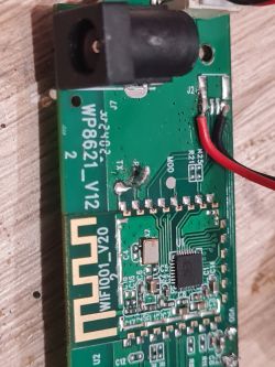
    Close-up of a circuit board with electronic components. I get this message via Button Read only OBK config

    CRC matches 0xEAB98F5!
    All read!
    Loaded total 0x1000 bytes
    It's not an OBK config, header is bad
    OBK config load failed.

    About Extract Config from Tuya binary

    Failed to extract Tuya keys - magic constant header not found in binary

    Add the backup file as an attachment

    and pictures of the board

    pinout :

    P0/UART2_TX/I2C2_SCL LED Red
    P1/UART2_RX/I2C2_SDA LED Blue
    P7/PWM1 Endstop
    P9/PWM3 Button
    P15/CS Motor on
    P22 / TDI IR receiver
    P23/TDO/ADC3 IR LED

    greet Martin
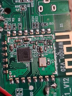
    Close-up of the PCB from a Xiaomei Fish Feeder showing traces, an integrated circuit, and markings.
    Close-up of Xiaomei Fish Feeder PCB with component labels and pinouts.
  • ADVERTISEMENT
  • ADVERTISEMENT
  • #4 21098623
    Nordlicht77
    Level 9  
    Hello
    I can't get any further. I installed Esphome and ltchiptool in venv on Raspberry
    I tried the same thing under Windows, the same thing comes out below

    When I try to convert the RBL to UF2 with LTchiptool, I get the following errors

    ltchiptool uf2 write -F bk7231n -b generic-bk7231t-qfn32-tuya -o openbkt.uf2 ';;download;OpenBK7231N_1.17.595.rbl'

    Usage: ltchiptool uf2 write [OPTIONS] [IMAGES]...
    Try 'ltchiptool uf2 write -h' for help.

    Error: Invalid value for '-b' / '--board': Board generic-bk7231t-qfn32-tuya does not exist

    Also the command ltchiptool -vv list boards the lsite is empty

    ltchiptool uf2 info works

    ltchiptool uf2 info OpenBK7231N_1.17.230.uf2
    I: Family: BK7231N / Beken 7231N
    I: Tags:
    I: - BOARD: generic-bk7231n-qfn32-tuya
    I: - DEVICE_ID: 455db1b9
    I: - BUILD_DATE: 7495ee64
    I: - FAL_PTABLE: 30315045646f776e6c6f61640000000000000000666c617368300000000000000000000000a0120000600a0000000000
    I: - OTA_FORMAT_2: 02
    I: - OTA_PART_LIST: 100000
    I: - OTA_PART_INFO: 100000646f776e6c6f616400
    I: Block count: 2485
    I: Total binary size: 635680
    I: Partition table:
    I: - download: 0x12A000+0xA6000 (664 KiB)

    I don't know if this is even the right way

    greet
    Martin
  • ADVERTISEMENT
  • #5 21098678
    divadiow
    Level 34  
    not sure what to suggest next.

    what's the bootloader version now? is it the 1.0.13 one?

    dunno if flashing a whole beken dump including 1.0.1 standard bootloader then doing standard OBK flash is an option. will the backup rom be expecting something specific to the 1.0.13 though?

    questions for anyone on the forum as I'm not sure.
  • #6 21098790
    Nordlicht77
    Level 9  
    Hi
    I took the bin with the name bk7231n-kickstart-ota-1.0.13-0x143000-no-encr.bin from the discord thread and flashed it and created a Yaml. It works, but you should also get it to run with OpenBK7231T_App
    It's all new to me in this way, I used to flash Tasmota on it and that's it
    But I'm willing to learn

    Where do I get the bootloader version 1.0.13 from?
  • #7 21098816
    divadiow
    Level 34  
    well, I know what I would do because I don't care about breaking my devices! but I'd rather someone with more experience offer their view first @p.kaczmarek2
  • #8 21099217
    Nordlicht77
    Level 9  

    Hello

    I made further progress by creating the UF2 file myself
    Visual Studio Code Esphome installed
    and then created a new project and a new board under PlatformIO
    Then looked in Windows in CLI what the board list query brings up and everything is there
    Then the command

    ltchiptool UF2 write -F bk7231n -b generic-bk7231n-qfn32-tuya -o openbkt.uf2 OpenBK7231N_1.17.594.rbl=device:download

    the file was created successfully
    Then uploaded the file via OTA update, unfortunately no change
    What else can be done, even if it breaks, so that I can think about it?
  • #9 21106421
    Nordlicht77
    Level 9  
    Hello
    Can't anyone help me then?
    You cannot create a bootloader with this software
  • #11 21107162
    Nordlicht77
    Level 9  
    Hi

    I got further with the help of @divadiow

    Thanks for that

    I did the following

    I downloaded the bootloader from @Oranż Metylowy from discord

    https://discord.com/channels/967863521511608370/1230509832029601793/1230615302916804651

    Then I flashed the file with the software ltchiptool-v4.11.1.exe with the settings in the picture

    Computer screen displaying the opened ltchiptool-v4.11.1.exe program, used for flashing files onto Beken 72xx chips, with settings for USB port and other parameters.

    A reboot was carried out

    I downloaded the build file test20240601.zip from @p.kaczmarek2 from this forum

    https://www.elektroda.com/rtvforum/topic4056377.html#21103288

    After the final packaging I took the file from the archive OpenBK7231N_App_UA_1.0.0.bin

    Then I flashed the file using the software ltchiptool-v4.11.1.exe with the settings in the picture

    The image shows a computer screen displaying the ltchiptool-v4.11.1 program.

    A reboot was carried out

    Then I looked to see if the access point appeared in the Wifi list, it was listed there
    I then connected to this point and I was automatically sent to the URL 192.168.4.1
    I set up Wifi there and saved it
    I looked in the Fritzbox to see which IP the device received and called up this URL

    And lo and behold it works


    Now I have to figure out how to set up these switches

    P0/UART2_TX/I2C2_SCL LED Red
    P1/UART2_RX/I2C2_SDA LED Blue
    P7/PWM1 endstop
    P9/PWM3 button
    P15/CS Motor on
    P22/TDI IR receiver
    P23/TDO/ADC3 IR LED

    my Yaml from esphome looked too

    Code: YAML
    Log in, to see the code
  • #12 21107248
    divadiow
    Level 34  
    Hi

    I guess you could start by confirming the LEDs, button and IR is correct by configuring these on each pin. channel 0

    "0": "LED;0",
    "1": "LED;0",
    "9": "Btn;0",
    "22": "IRRecv;0",
    "23": "LED;0"

    once configured a button push should turn on all 3 LEDs.

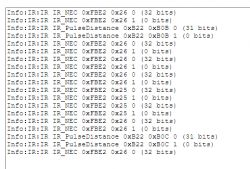
    reboot to start the IR driver and then point a remote control at the device and push some buttons. you should see some IR commands appear in the log in the web application. eg

    Screenshot of IR command log.
  • #13 21107589
    Nordlicht77
    Level 9  
    hi
    the bottom works but the IR led doesn't work, it's this one

    https://discord.com/channels/967863521511608370/1230509832029601793/1230874920452358245

    The P15/CS motor must be linked to the P7/PWM1
    The motor moves a slide when it extends, the endstop goes to open and when it goes back it goes to closed and then the motor has to be off again

    The IR LEDs are two pieces that are given and are triggered when the food is low
  • #14 21107630
    p.kaczmarek2
    Moderator Smart Home
    So it's another device with 00000000000000000000000000000000 keys?

    I've been adding support of building that to N platform script, but my linux knowledge is rusty, I am C guy. Here is what I do. First build firmware with 0000 keys:
    Screenshot showing changes in the script file for firmware building.
    (edit: this screenshot above is not fully correct, I am not using zerokeys binary at this stage anymore, as it caused combine to fail)
    Then manually merge our QIO with original dogness bootloader (sent by another user):
    A code snippet from a script for building firmware using zerokeys for the Beken BK7231N device.
    I tried to follow these steps:
    Screenshot from a forum about device flashing issues.
    Can you make a full 2MB backup of your device and test my binary? I don't have this type of Beken to test
    Helpful post? Buy me a coffee.
  • #15 21107661
    divadiow
    Level 34  
    @Nordlicht77 is already running OBK using a combination of a bootloader from elsewhere and that unencrypted OBK compile from the zip in the Dogness thread.

    The user is at the stage where pins and an autoexec need sorting.

    But at the moment there are other unknowns still, like ota upgrades and what exactly the bootloader flashed was.
  • #16 21107677
    p.kaczmarek2
    Moderator Smart Home
    I know, but I hoped that he can help with testing my binary so I can know whether it works or not. If it works, then I can finally add it to our public builds system so everyone can benefit.
    Helpful post? Buy me a coffee.
  • #17 21107685
    Nordlicht77
    Level 9  

    @p.kaczmarek2
    I did it as above, flashed both files only secondly the file OpenBK7231N_App_QIO_1.0.0
    There is no WiFi point and the device cannot be seen in the Fritz box

    Addendum
    I have now just flashed your file again with the start address 0x0 and it works
  • #18 21107697
    divadiow
    Level 34  
    p.kaczmarek2 wrote:
    but I hoped that he can help with testing my binary so I can know whether it works or not.

    Ah I seeee. Read your reply from the wrong angle.

    Good news on the testing @Nordlicht77
  • #19 21107701
    Nordlicht77
    Level 9  

    so far it looks like this
    "pins": {
    "0": "LED;63",
    "1": "LED;62",
    "7": "dInput;56",
    "9": "Rel;0",
    "15": "Rel;2",
    "22": "dInput;41",
    "23": "dInput;40"
    },

    "22": "dInput;41",
    "23": "dInput;40"
    in log :
    Info:GEN:CHANNEL_Set channel 41 has changed to 0 (flags 0)
    Info:GEN:CHANNEL_Set channel 41 has changed to 1 (flags 0)
    but not in gui as bottom

    "7": "dInput;56",
    in log :
    Info:GEN:CHANNEL_Set channel 56 has changed to 1 (flags 0)
    Info:GEN:CHANNEL_Set channel 56 has changed to 0 (flags 0)
    but not in gui as bottom

    "15": "Rel;2",
    in log :
    no entry
    but in Gui there is a bottom where you can turn the engine on and off

    "0": "LED;0",
    "1": "LED;0",
    in log :
    no entry
    but in Gui there is a led and a bottom where you can turn it on and off
  • #20 21107907
    p.kaczmarek2
    Moderator Smart Home
    Change those super-high channel numbers to something in range 0 - 10 and then in Web App assign "Toggle" channel types to channels you want to be able to toggle.

    Added after 4 [hours] 55 [minutes]:

    I added encryption key reading to flasher, can you get latest build:
    https://github.com/openshwprojects/BK7231GUIFlashTool/releases/tag/v1.2
    And do just "Do firmware backup (read) only)" and show me what is there:
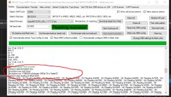
    Screenshot of BK7231 Easy UART Flasher tool showing reading success.
    Can you check if it's working for you and what's it showing?
    Helpful post? Buy me a coffee.
  • ADVERTISEMENT
  • #21 21108711
    Nordlicht77
    Level 9  
    Hi
    with bk7231flasher_1.3and bk7231m and the file OpenBK7231M_QIO_1.17.606.bin it works and looks like this

    Code: Arduino
    Log in, to see the code


    I've moved on
    It looks like this so far

    "pins": {
    "0": "LED;5",
    "1": "LED;4",
    "7": "dInput;1",
    "9": "dInput;3",
    "15": "Rel;2",
    "22": "dInput;7",
    "23": "LED;6"
    },

    autoexec.bat

    setChannelLabel 1 "Endstop"
    setChannelType 1 Toggle
    setChannelLabel 2 "Motor"
    setChannelType 2 Toggle
    setChannelLabel 3 "Bottom"
    setChannelType 3 Toggle
    setChannelLabel 4 "LED Blue"
    setChannelType 4 Toggle
    setChannelLabel 5 "LED Red"
    setChannelType 5 Toggle
    setChannelLabel 6 "IRRecv"
    setChannelType 6 Toggle
    setChannelLabel 7 "IR LED"
    setChannelType 7 Toggle
    SetButtonTimes 3 3 5
    alias bottomevent backlog setChannel 2 1;addRepeatingEvent 10 3 setChannel 3 0

    addChangeHandler Channel1 == 1 backlog setChannel 2 0
    addChangeHandler Channel3 == 1 bottomevent

    1.How do I get IRRecv ​​to automatically turn on when restarting?
    2.If I set the two LEDs 4 and 5 to LED under cfg_pins, they turn on and off, I do a reboot and it no longer works and the red one is on
    3 Is it possible to replace the channel number with just a name in mqtt
    4.is then BK7231M correct or BK7231N It's a Belon BL2028N
  • #22 21109293
    p.kaczmarek2
    Moderator Smart Home
    Nordlicht77 wrote:

    1.How do I get IRRecv ​​to automatically turn on when restarting?

    I am confused. Why did you name a channel like that? If you really want to receive IR, use IRRecv pin. It will automatically start IR driver after device reboot.
    On the other hand, if you are asking on how to set channel value - well , there is setChannel command.
    https://github.com/openshwprojects/OpenBK7231T_App/blob/main/docs/commands-extended.md

    Nordlicht77 wrote:

    2.If I set the two LEDs 4 and 5 to LED under cfg_pins, they turn on and off, I do a reboot and it no longer works and the red one is on

    What do you mean, when turn on and off? They should follow channel values as long as they are configured.
    If LED is on channel 5:
    
    "0": "LED;5",
    

    then toggleChannel 5 command should work even after restart.

    Nordlicht77 wrote:

    3 Is it possible to replace the channel number with just a name in mqtt

    I don't think so, but I can add this feature for you later.

    Nordlicht77 wrote:

    4.is then BK7231M correct or BK7231N It's a Belon BL2028N

    BL2028N come in at least two versions, with Tuya keys and with 00000 keys, so it's more complicated than that.

    Can you please be more specific about the issues or maybe create a smaller script to demonstrate the problem?
    Helpful post? Buy me a coffee.
  • #23 21109333
    Nordlicht77
    Level 9  

    If I in the config "22": "xInput;7", and "23": "LED;6" setting also works,
    but 22 has to be on with "22": "IRRecv;7", "23": "LED;6"
    No reaction from the LED, it is a light barrier made up of two LEDs, see discord link above

    For LED 5 and LED 4, after changing them, I switch them back to LED and save it so that the two lamps can be controlled separately and also turned on and off
    If I do a restart, the red LED lights up when I start and both can no longer be controlled again until I set the config setting to dinput memory and back to led and memory then I can turn them on and off again

    I posted my Yaml open and the LEDs also worked
  • #24 21110419
    Nordlicht77
    Level 9  

    Hi @p.kaczmarek2
    Should I make a video about the LED?
    and send you a private message
  • #25 21110440
    p.kaczmarek2
    Moderator Smart Home
    If you can explain the issue any better or phrase your question, please do. I am not sure why are you changing between IR Receiver and dInput?

    Or can you make a simplest demo of the issue, only with pins that are necessary?
    Helpful post? Buy me a coffee.
  • #26 21111019
    Nordlicht77
    Level 9  
    Hi
    Sorry, I actually speak German

    I used the old bootloader and my Yaml and only wrote the things here that don't work

    # P0/UART2_TX/I2C2_SCL LED Red
    #The red LED is switched off on the old bootloader and the yaml and can be switched on and off using a switch
    #In your bin the lamp is on when you start and cannot be controlled with the setting "0": "LED;0" and is on all the time
    #For example, if I change this setting to "input": "LED;0" and save it and then set it back to "0": "LED;0" and then save I can turn the lamp off and on in Gui using Toogle
    #If I restart now, I can't control it via GUI and the lamp is on

    output:
    - platform: gpio
    id: output_led_red
    pin: GPIO0
    #P23/TDO/ADC3 IR LED
    - platform: gpio
    id: output_led_IR
    pin: GPIO23
    #Shows current WiFi status blue LED
    #P1/UART2_RX/I2C2_SDA LED Blue wifi status
    status_led:
    pin:
    number: GPIO1
    inverted: true

    light:
    # Light switches to control leds red
    - platform: binary
    name: "virtual led-red"
    id: led_red
    output: output_led_red
    effects:
    - strobe:
    name: led_red_strobe
    # Light switches to control leds red
    - platform: binary
    name: "Led receiver"
    id: led_IR
    output: output_led_IR

    binary_sensor:
    # IR_receiver
    #P22 / TDI IR receiver
    #LED receiver must be on so that Receiver_IR status reports whether the container is full or empty
    #There is no reaction to your file with the setting "IRRecv;7", "23": "LED;6" and nothing can be seen in the log
    - platform: gpio
    pin:
    number: GPIO22
    mode:
    input: true
    pullup: true
    id: IR_receiver
    name: "Receiver_IR"

    Hinzugefügt nach 4 [Stunden] 44 [Minuten]:

    I don't know why I have now inserted this start command and the red LED flashes briefly afterwards and I can control it via Gui
    With the setting, the blue LED correctly shows the WiFi status
    I don't know about the Irish, but that's how it works
    I'll try some more and read more

    The settings now look like this
    Code: YAML
    Log in, to see the code


    Someone here happens to be using MQTT with Openhab and can show me an example
  • #27 21114229
    Nordlicht77
    Level 9  
    Hello
    So far it looks like this

    über den toggle steht der status On Off kann man dies ausblenden
    You can hide this using the toggle that shows the status On Off
    Kann man einstellen das die Rote Led blinkt
    Does this function exist?effect: led_red_strobe
    Template
    Code: Arduino
    Log in, to see the code

    startup command line
    Code: Arduino
    Log in, to see the code

    autoexec.bat
    Code: Arduino
    Log in, to see the code

    openhab thing MQTT
    Code: Arduino
    Log in, to see the code

    openhab Items
    Code: Arduino
    Log in, to see the code

    openhab rules
    Code: Arduino
    Log in, to see the code
  • #28 21115904
    Nordlicht77
    Level 9  
    Google translate can be that bad because of translation
    Is there last change or last update from Relay in MQTT
    I flashed a second device with the bin, there are problems with the Mac, the devices have the same Mac, it has to be installed somehow so that you can probably change the Mac during the first setup Wifi data or it can be set up directly in the bin
  • #29 21115911
    p.kaczmarek2
    Moderator Smart Home
    You can change MAC in OBK config settings ,you can also do it in our flasher and on web app.
    Helpful post? Buy me a coffee.
  • #30 21115921
    Nordlicht77
    Level 9  
    I didn't find it in BK7231 Flasher
    What is the Web app setting for?
    https://openbekeniot.github.io/webapp/
    I get a white page when I open it
    Which app does the program work best with?
    There is also an RBL for updating via the web for the BK7231M 1.17.611

Topic summary

The discussion centers on flashing and configuring the Xiaomei Fish Feeder device, which uses the BK7231N/BK7231M chip and Belon BL2028N board, with OpenBK7231N firmware. The main challenge is successfully flashing the device with OpenBK7231N_App firmware and achieving WiFi connectivity and device visibility on networks like Fritzbox. Initial attempts using standard OpenBK7231N_QIO binaries report successful flashing but no network presence. The device uses an unusual bootloader (version 1.0.13) and partition layout, requiring a specific kickstart bootloader (bk7231n-kickstart-ota-1.0.13-0x143000-no-encr.bin) to enable OpenBeken firmware compatibility. Tools like ltchiptool and bk7231flasher are used for flashing and backup, with some issues encountered in board recognition and key extraction from Tuya binaries due to missing magic headers. Successful flashing involves merging original bootloader with OpenBK firmware and using correct start addresses (0x0). Configuration challenges include correct pin assignments for LEDs, buttons, IR LEDs, and motor controls, with detailed YAML configurations discussed. Users report issues with LED control persistence after reboot and IR LED activation. MAC address conflicts on multiple devices are addressed by changing MAC in OBK config or flasher tools. The OpenBK7231T_App web interface requires access via the OBK panel to function properly. Some users achieve partial success with ESPHome firmware as an alternative. The community shares firmware builds, bootloader files, and configuration templates, emphasizing the need for correct bootloader versions, key handling (including zeroed keys), and pin role assignments to achieve full device functionality including WiFi connectivity, OTA updates, and peripheral control.
Summary generated by the language model.
ADVERTISEMENT