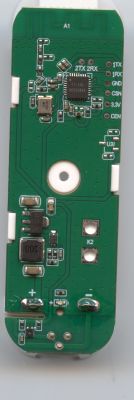
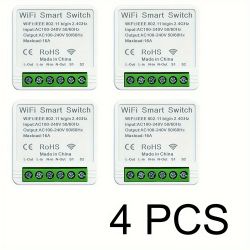
I bought these smart switches from Temu ( manual pdf ):
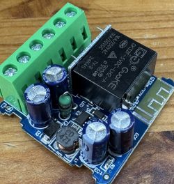
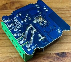
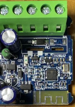
After disassembling, I saw that the CPU was under the relay . After soldering I was greeted by the BL602. All the necessary pads were labelled:
 ->
-> 
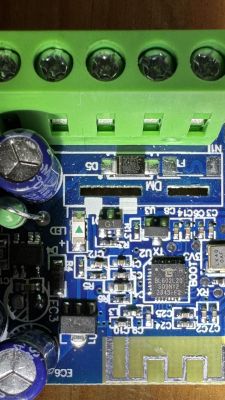
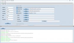
Then I was able to flash OpenBK with BLDevCube :
Then I had to figure out the correct GPIOs :
Now everything works as expected.
A few more notes:
I destroyed two of them because I wanted to solder all the wires to their tiny pads. You can save yourself a lot of soldering work if you only solder 3V3 and GND and find other places for them. For example, 3V3 is also available at the bottom left of the LDO and GND on the back of the board at the negative pole of a capacitor. I have also soldered a 10kOhm resistor to 3V3 and held it to BOOT when booting. This can then be released again and TX and RX can be held on the solder pads with two Dupont cables for the duration of flashing.

After disassembling, I saw that the CPU was under the relay . After soldering I was greeted by the BL602. All the necessary pads were labelled:

 ->
-> 

Then I was able to flash OpenBK with BLDevCube :

Then I had to figure out the correct GPIOs :
  "pins": {
    "2": "TglChanOnTgl;1",
    "3": "Rel;1",
    "20": "LED;1",
    "22": "Btn;1"
  }
Now everything works as expected.
A few more notes:
I destroyed two of them because I wanted to solder all the wires to their tiny pads. You can save yourself a lot of soldering work if you only solder 3V3 and GND and find other places for them. For example, 3V3 is also available at the bottom left of the LDO and GND on the back of the board at the negative pole of a capacitor. I have also soldered a 10kOhm resistor to 3V3 and held it to BOOT when booting. This can then be released again and TX and RX can be held on the solder pads with two Dupont cables for the duration of flashing.


