Here is a teardown for a generic WiFi Smart Power Strip UK Model no. SM-SO301K that I purchased by mistake from Amaozn UK Link to Amazon UK
![[BK7231N / CB3S] Teardown WiFi Smart Power Strip UK [BK7231N / CB3S] Teardown WiFi Smart Power Strip UK](https://obrazki.elektroda.pl/4535041600_1678464108_thumb.jpg)
I already have the Zigbee version and it works well with Home Assistant so I thought I'd try OpenBK with this one.
![[BK7231N / CB3S] Teardown WiFi Smart Power Strip UK [BK7231N / CB3S] Teardown WiFi Smart Power Strip UK](https://obrazki.elektroda.pl/9471230200_1678464253_thumb.jpg)
Disassembly was simple, rubber bungs on the back covering 8 small screws.
****NOTE****
Make sure you disconnect the device from any mains supply before opening the case and do not be tempted to plug it back in once you have removed the cover, ensure safe electrical working practices are carried out at all times.
![[BK7231N / CB3S] Teardown WiFi Smart Power Strip UK [BK7231N / CB3S] Teardown WiFi Smart Power Strip UK](https://obrazki.elektroda.pl/6302252700_1678464358_thumb.jpg)
The cover just prises off, there was no glue or concealed catches.
![[BK7231N / CB3S] Teardown WiFi Smart Power Strip UK [BK7231N / CB3S] Teardown WiFi Smart Power Strip UK](https://obrazki.elektroda.pl/1677422500_1678464412_thumb.jpg)
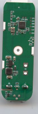
This is the main PCB and I have identified all of the relevant parts, you can see the CB3S module in the centre it uses the BK7231N chip.
There are four mains outputs, one 5V USB output, two separate LED indicators (red and blue) and one button input.
![[BK7231N / CB3S] Teardown WiFi Smart Power Strip UK [BK7231N / CB3S] Teardown WiFi Smart Power Strip UK](https://obrazki.elektroda.pl/2506622400_1678464716_thumb.jpg)
I temporarily soldered wires to the +3v3, Gnd, TXD and RXD pins on the CB3S module and attached them to a serial UART plugged into my Windows computer.
I downloaded the BK7231 GUI flasher tool from here, unzipped it and ran it.
I then clicked the button 'Download latest from web' and after downloading, selected that file to flash to the module.
Ive done this before so I selected the COM port of my Serial UART and opted to 'Do firmware write (no backup!)'
Once the flash procedure started I shorted CEN (Pin 3) to Gnd for a short pulse and the flash procedure continued to completion.
![[BK7231N / CB3S] Teardown WiFi Smart Power Strip UK [BK7231N / CB3S] Teardown WiFi Smart Power Strip UK](https://obrazki.elektroda.pl/1412440200_1678465394_thumb.jpg)
Head over to https://github.com/openshwprojects/BK7231GUIFlashTool for a detailed overview of how this tool works.
Confident that the procedure had worked, I desoldered my temporary wires and reassembled the device before plugging into the mains supply.
Once I'd got the WiFi settings completed and connected to my AP, I then set up the config as follows:
![[BK7231N / CB3S] Teardown WiFi Smart Power Strip UK [BK7231N / CB3S] Teardown WiFi Smart Power Strip UK](https://obrazki.elektroda.pl/2993364600_1678467027_thumb.jpg)
It worked great!
Well it didn't entirely, I found a bug with the Btn_tgl_all function but that was fixed overnight once I'd raised it on guthub.
Thanks for the amazing response!
Cool? Ranking DIY


![[BK7231N / CB3S] Teardown WiFi Smart Power Strip UK [BK7231N / CB3S] Teardown WiFi Smart Power Strip UK](https://obrazki.elektroda.pl/7326561400_1678482434_thumb.jpg)