Hi all,
I want to share a teardown and flash experience for a device I couldn't find in the database so far. It's a single on/off power socket WiFi switch with power monitoring feature.
Tuya Smart Plug (EU)
Manufacturer: Aoyan
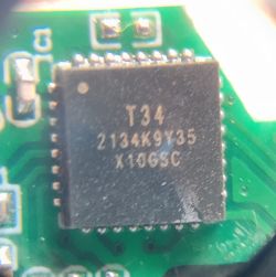
Chip: T34 (same setting as BK7231N)
Connection: WiFi
bought here: https://de.aliexpress.com/item/1005006777059625.html
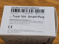
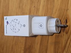
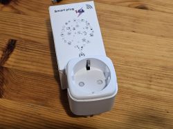
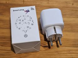
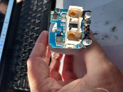
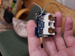
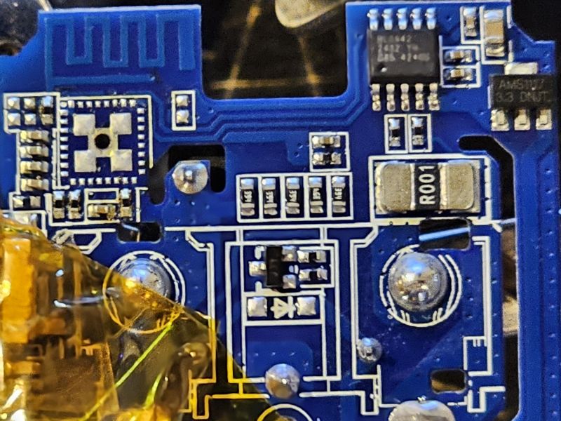
After usual disassembly for this device type (best working with a pipe wrench on all 4 corners at the top), I was quite surprised to find a different PCB layout without separate module - just a T34 chip without any test solder points and antenna integrated in the mainboard - note that on the following photo, the T34 chip has already been removed, it sits where the 4 big ground pads are located:
I found some useful information about the chip and how to deal with it here: https://www.elektroda.com/rtvforum/topic4036975.html
- so I did following steps:
1. desoldering the chip with hot air
2. tracing back possible solder points for GND, 3V3, TX & RX
3. either flashing the chip desoldered and then put it back or, soldering it back first and then flashing
4. setting up OpenBK firmware
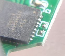
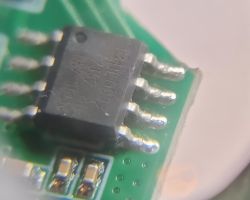
I share some photos of the important places:
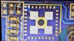
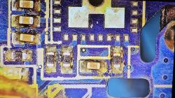
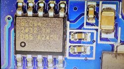
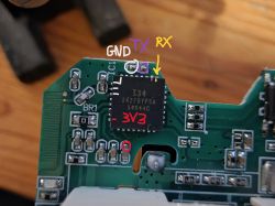
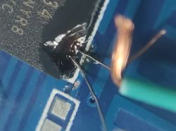
The tracing back resulted in following finding: all points can be easly accessed via connected BL0942 chip (I assume power monitoring chip):
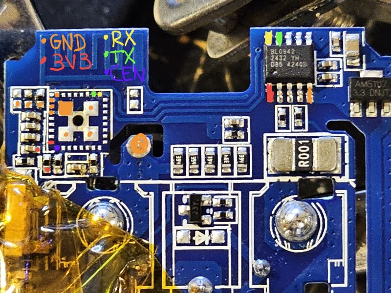
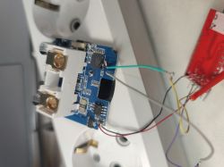
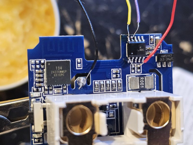
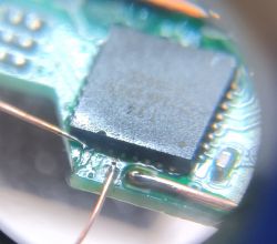
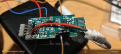
By connecting 4 wires to the mentioned points (I chose 3 pins at BL0942 chip and 1 convenient big pad for GND) and flashing with OpenBK Flasher (setting to BK7231N), the flashing can be done without need to desolder. I have 4 devices of the same kind, so I used one for analysis and flashed the 3 other ones without any desoldering, very easy. CEN is not necessary, just interrupt 3V3 in the process to reset and start flashing.
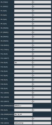
Last step is finding the pinout - I used OpenBK Web application and found following settings:
P14 - Rel [Channel 1]
P24 - WifiLED
P26 - Btn [Channel 1]
Comment: The LED on P24 is blue and is optional if required for WiFi connection. There is a red LED as well that is linked to the relay on P14, so this one will automatically switch on and off with the relay.
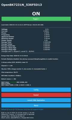
EDIT: to enable power monitoring, add 'startDriver BL0942' either to autoexec.bat or startup commands. My autoexec.bat is as follows:
I also recommend to set following flags: 2; 10; 25; 38; 40
Here I also attach the read result.
Hope that this device can be added to the database and hopefully it helps others who bought the same device. Cheers =)
I want to share a teardown and flash experience for a device I couldn't find in the database so far. It's a single on/off power socket WiFi switch with power monitoring feature.
Tuya Smart Plug (EU)
Manufacturer: Aoyan
Chip: T34 (same setting as BK7231N)
Connection: WiFi
bought here: https://de.aliexpress.com/item/1005006777059625.html


After usual disassembly for this device type (best working with a pipe wrench on all 4 corners at the top), I was quite surprised to find a different PCB layout without separate module - just a T34 chip without any test solder points and antenna integrated in the mainboard - note that on the following photo, the T34 chip has already been removed, it sits where the 4 big ground pads are located:

I found some useful information about the chip and how to deal with it here: https://www.elektroda.com/rtvforum/topic4036975.html
- so I did following steps:
1. desoldering the chip with hot air
2. tracing back possible solder points for GND, 3V3, TX & RX
3. either flashing the chip desoldered and then put it back or, soldering it back first and then flashing
4. setting up OpenBK firmware
I share some photos of the important places:


The tracing back resulted in following finding: all points can be easly accessed via connected BL0942 chip (I assume power monitoring chip):

By connecting 4 wires to the mentioned points (I chose 3 pins at BL0942 chip and 1 convenient big pad for GND) and flashing with OpenBK Flasher (setting to BK7231N), the flashing can be done without need to desolder. I have 4 devices of the same kind, so I used one for analysis and flashed the 3 other ones without any desoldering, very easy. CEN is not necessary, just interrupt 3V3 in the process to reset and start flashing.

Last step is finding the pinout - I used OpenBK Web application and found following settings:
P14 - Rel [Channel 1]
P24 - WifiLED
P26 - Btn [Channel 1]
Comment: The LED on P24 is blue and is optional if required for WiFi connection. There is a red LED as well that is linked to the relay on P14, so this one will automatically switch on and off with the relay.
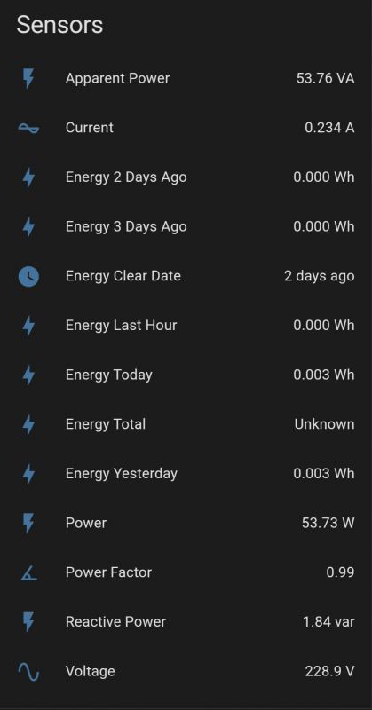
EDIT: to enable power monitoring, add 'startDriver BL0942' either to autoexec.bat or startup commands. My autoexec.bat is as follows:
Spoiler:
startDriver BL0942
startDriver NTP
ntp_setServer xxx.xxx.xxx.xxx
//replace xxx with your IP address above
ntp_timeZoneOfs x
// replace x above with value of your time zone
startDriver BL0942
startDriver NTP
ntp_setServer xxx.xxx.xxx.xxx
//replace xxx with your IP address above
ntp_timeZoneOfs x
// replace x above with value of your time zone
I also recommend to set following flags: 2; 10; 25; 38; 40
Here I also attach the read result.
Spoiler:
Hope that this device can be added to the database and hopefully it helps others who bought the same device. Cheers =)


![[T34 ] Teardown & Flashing Guide for Aoyan Tuya Smart Plug (EU) [T34 ] Teardown & Flashing Guide for Aoyan Tuya Smart Plug (EU)](https://static.elektroda.pl/attach/thumb/IMG_4286_1492735.jpg)
![[T34 ] Teardown & Flashing Guide for Aoyan Tuya Smart Plug (EU) [T34 ] Teardown & Flashing Guide for Aoyan Tuya Smart Plug (EU)](https://static.elektroda.pl/attach/thumb/IMG_4285_9388884.jpg)
![[T34 ] Teardown & Flashing Guide for Aoyan Tuya Smart Plug (EU) [T34 ] Teardown & Flashing Guide for Aoyan Tuya Smart Plug (EU)](https://static.elektroda.pl/attach/thumb/IMG_4284_1403809.jpg)
