logo elektroda
logo elektroda
X
logo elektroda

Teardown and Reflashing of Tuya Smart Socket EU20A with LN882HKI Chip Analysis

bogdanelhh 3621 22
ADVERTISEMENT
  • #1 21333751
    bogdanelhh
    Level 3  
    Teardown of Tuya Smart Socket EU20A Wifi Smart Plug With Power Monitoring Smart Life APP Remote Control Support Google Assistant Alexa bought from aliexpress here https://vi.aliexpress.com/item/10050078840687...6hMe&gatewayAdapt=glo2vnm#nav-description
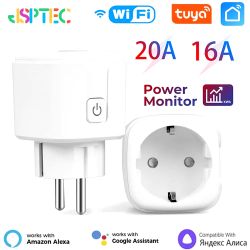
    Tuya Smart Socket EU20A WiFi power monitoring plug.

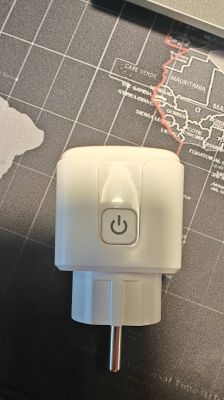
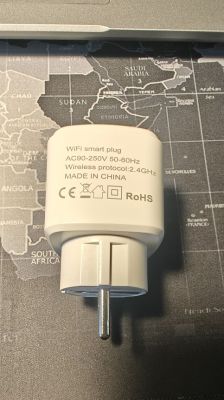
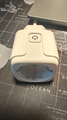
    Product looks like this:

    White smart plug with a power button on a dark background. View of a white Tuya EU20A Wi-Fi smart plug with technical specifications on a map background. White Tuya smart plug lying on a world map.

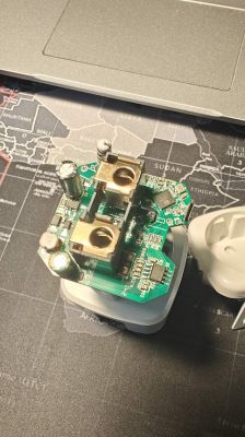
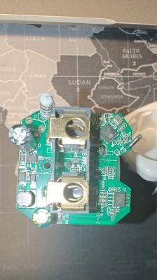
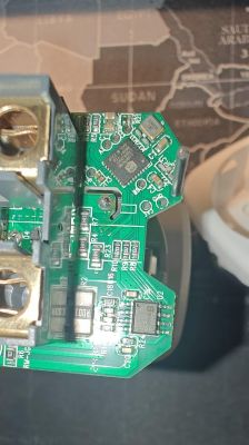
    Disassembled looks like this:
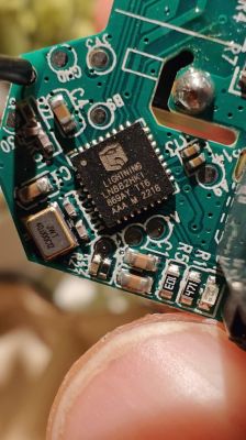
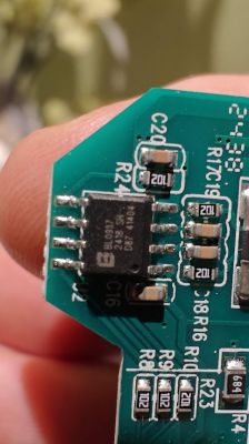
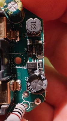
    Disassembled Wi-Fi smart plug lying on a world map. Close-up of the dismantled electronic board of a Tuya smart plug with visible components. Close-up of a circuit board with a microchip in a smart socket. Close-up of a circuit board with a chip labeled LIGHTNING LN882HV16. Close-up of a circuit board with a BL0937 chip and resistors. Close-up of the internal circuit of a disassembled Tuya Smart Socket.

    After some reads on this forum and also some investigation, I'm dealing with :
    Part NumberPackage Flash SizeTemperature
    LN882HKIQFN-32, 5mm pitch2MB Flash-40℃~105℃

    Haven't found yet documented the pinout of this chip here, and I must admit that my time is very limited on investigation. But I managed to identify on board the following pins: GND, 3V3, A9, B9. Considering the schematic below A9 is for switching the boot mode and B9 is TXD0 of chip which should print out to serial port.
    B8 (RXD0) is missing any breakouts and that's why the delay on hooking into it as I need to figure out how to solder to that tiny pin without breaking anything.
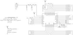
    Electrical schematic showing connections and pin layout for the WCN-LN882H chip.

    Chip used for energy monitoring is marked with BL0937, which I didn't investigate about it by now considering my focus on switching firmware of this chip and after that managing the peripherals.

    I'll keep this updated with my investigation while I'm wondering if anyone managed to reflash this specific model.
    AI: What is your ultimate goal with reflashing the Tuya Smart Socket EU20A? Are you aiming to change its functionality or integrate it with a specific system?
    I am planning to integrate it with Home Assistant
    AI: Have you tried any specific methods or tools for reflashing the LN882HKI chip so far, and if so, what were the results?
    Not yet
  • ADVERTISEMENT
  • ADVERTISEMENT
  • #4 21334409
    bogdanelhh
    Level 3  
    Thanks Max. I managed to flash it successfully. It seems I was trying the wrong serial :D I haven't managed to dump the original firmware, but I don't care about it.

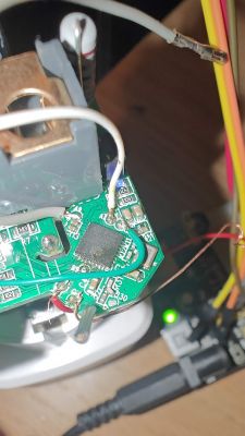
    Close-up of a PCB with soldered wires in various colors: red, white, gray, green, and an unsheathed wire.

    I soldered the wires as it shows in the picture above and:
    Red is 3v3
    Unshielded one is GND
    Gray is A9 which I shorted to the unshielded GND while flashing
    Green is TX of LN882HKI
    White is RX of LN882HKI

    My time for investigation is done for the day but since flashing is successful tomorrow I'll trace the config to fully functional device (fingers crossed).

    Edit: I used external 3v3 with common ground.
  • ADVERTISEMENT
  • #5 21334441
    max4elektroda
    Level 20  
    Good news!
    So next task will be to trace the pins to BL0937 so you can configure them in the config page.
  • #6 21335189
    bogdanelhh
    Level 3  
    Here is the config:

    Code: JSON
    Log in, to see the code
  • ADVERTISEMENT
  • #8 21335360
    bogdanelhh
    Level 3  
    >>21335223

    The stock firmware I wasn't able to dump it. But I will post a backup here after installing on the next one, as this one was already configured with MQTT, WiFi and HA. I'll be back today with the blank backup.

    Added after 4 [hours] 43 [minutes]:

    Here is the bin file. I extracted it by config page. But during retrieval device lost connection multiple times, seems that web service is pretty unstable. However the first device I flashed has same issues with web config but in Home Assistant is stable.

    I suspect this behavior is because is logging constantly, and I should update the mqtt message update interval but I need to check the docs for that.
  • #9 21338644
    divadiow
    Level 34  
    bogdanelhh wrote:
    Here is the bin file. I extracted it by config page.

    thank you but this is not a backup of the factory firmware taken before flashing OpenBeken. Not to worry.
  • #10 21339154
    bogdanelhh
    Level 3  
    >>21338644
    I tried to extract that stock firmware but I suspect something was wrong in it because I waited for 2 screens of dots and it was not done after 1.5 hrs.
  • #13 21450678
    romicacotoiul
    Level 2  
    Hello, I am trying to flash this socket. But I don't manage to get it in download mode, I suppose (I am pulling A9 to GND and checked lots of times the connections to UART (I'm using a CH340 module (could it be that it doesn't support 2000000 baud?). After powering up the module, the onboard LED starts to flash. Is this expected even in download mode? Thanks.
  • #14 21450692
    divadiow
    Level 34  
    romicacotoiul wrote:
    After powering up the module, the onboard LED starts to flash. Is this expected even in download mode?


    No, this sounds like the device is booting into Tuya firmware. Are your grounds all connected and is there continuity between them all? Are you removing all power between.retries - USB UART adaptor AND 3.3v power source (Assuming you're not using 3.3v from USB UART only)?

    Added after 1 [minutes]:

    Feel free to post pics detailing your whole layout in case we can spot something missing
  • #15 21450694
    romicacotoiul
    Level 2  
    Thanks a lot! Bad contacts on some alligators dupont connectors. After securing them, I got two sockets flashed.
  • #16 21450696
    divadiow
    Level 34  
    >>21450694

    Ah excellent. Did you take any backups? 🤓
  • #17 21451857
    Powl654
    Level 3  
    Hello,
    I am also trying to flash this device, but it is not working using the GUI (see this post).
    But maybe I am not in the correct download mode?
    I'm also using a CH340 module and A9 to is pulled to GND.

    Powering up the module (A9 is pulled to GND) turns the blue LED on the socket constantly on but not as bright as normal.
    Is that the correct LED behavior for download mode?

    Thanks!
  • #18 21451913
    max4elektroda
    Level 20  
    Powl654 wrote:
    Powering up the module (A9 is pulled to GND) turns the blue LED on the socket constantly on but not as bright as normal.

    Exactly, this will show you at least entered download mode.

    Since flashing starts, I would suggest
    Lower speed of serial, e.g. only use 115200 (instead of 921000)
    Shorten the cables
    Use a different power supply, especially if you are using the USB adapter to power the device
  • #19 21453362
    Powl654
    Level 3  
    Thank you, I will try the different speed.

    Yes, the cables are quite long (60cm + 20cm dupon male-female cables).
  • #20 21453808
    Powl654
    Level 3  
    It worked after shortening the wires and reducing the speed to 921000! :-)

    As of now I connected to the sockets AP and entered my wifi network credentials. After rebooting the socket, I connected again to its new IP within my network.

    Now I need to find out how to set up my Tuya socket with LN882HKI chip correctly. I want to hook it up to the micro inverter of my two solar panels to track the energy production by looking at the socket's webpage or if it exists, by an App since I am not having something like Home Assistant in my network.

    What do I have to do next?
    1.) I assume I need to configure the pins in the config page. If yes, is there a template or a howto?
    2.) Where exactly do I have to configure the pins? "Config" -> "Config Module" or "Launch Web Application"?
    3.) And do I need to calibrate the socket to measure the power correctly?

    Thank you so much for all your work and help!
  • #21 21453872
    max4elektroda
    Level 20  
    If you find the same plug somewhere, there's a good chance, someone posted a template you can use in the webapp to configure your pins (IIRC it's the "import" page there).
    Or you simply do it by hand, directly in "Config" --> "Configure Module" or in the WebApp.

    If you don't know the pins, you can also try the "pin doctor" in the app.

    After power metering chip is configured correctly (you will see some values, even if they are not correct) you need to calibrate the chip (on the "Tools" tab in the app).
  • #23 21580275
    p.kaczmarek2
    Moderator Smart Home
    LSPA9 plugs came with different chips and circuits. I saw WB2S ones, CB2S, and even lately T34-based. Not to mention the LN882H from this topic and similar...

    Added after 19 [seconds]:

    luckily all those chips are supported by OBK.
    Helpful post? Buy me a coffee.

Topic summary

The discussion revolves around the teardown and flashing of the Tuya Smart Socket EU20A, which features WiFi connectivity and power monitoring capabilities. Users share their experiences with disassembling the device, identifying pin connections for flashing, and troubleshooting issues related to firmware extraction and flashing processes. Key components mentioned include the LN882HKI chip and BL0937 power monitoring IC. Successful flashing was achieved by connecting the correct pins and using an external 3.3V power source. Users also discuss challenges in obtaining the original firmware and the stability of the device post-flashing, particularly in relation to MQTT and Home Assistant integration.
Summary generated by the language model.
ADVERTISEMENT