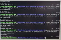
I am going to show you how to flash the BSEED E-Serie 4Gang Switch without any soldering:
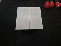
First you need to get the switch out of the metal frame, by bending these clips with a screwdriver:
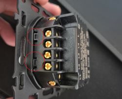
Now let's get the upper part out of the switch. Again we are using a very small screwdriver:
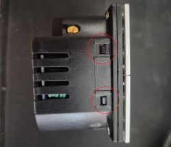
You will get the upper part with the buttons and the module inside. You open the small screws:
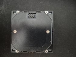
Then you can open the upper module to receive the board, front & back. You will see the two pins for 3.3V and GND.
In fact it is two boards, soldered to each other. Don't try to separate them! They are soldered to each other:
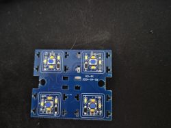
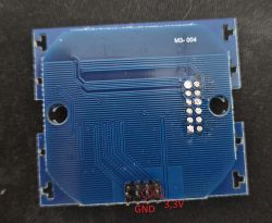
If you turn it to the side, you can look between both boards and you will find the CBU chip:
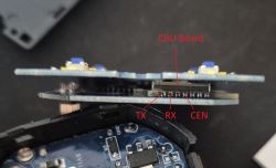
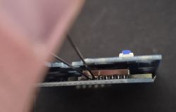
Instead of soldering, try it with two sewing needles and a very steady hand. If you manage holding these 2 needles with one hand, you can use your second hand for the CEN-Port:
Tuya config partition:
Description of pins:
See also attached the firmware dump.

First you need to get the switch out of the metal frame, by bending these clips with a screwdriver:

Now let's get the upper part out of the switch. Again we are using a very small screwdriver:

You will get the upper part with the buttons and the module inside. You open the small screws:

ADVERTISEMENT
Then you can open the upper module to receive the board, front & back. You will see the two pins for 3.3V and GND.
In fact it is two boards, soldered to each other. Don't try to separate them! They are soldered to each other:


If you turn it to the side, you can look between both boards and you will find the CBU chip:

Instead of soldering, try it with two sewing needles and a very steady hand. If you manage holding these 2 needles with one hand, you can use your second hand for the CEN-Port:

Tuya config partition:
Code: JSON
Description of pins:
Device configuration, as extracted from Tuya:
- Button (channel 1) on P15
- LED (channel 1) on P8
- Backlit IO pin on P14
- LED (channel 3) on P10
- Relay (channel 2) on P26
- LED (channel 2) on P11
- Relay (channel 1) on P24
- Relay (channel 3) on P6
- Relay (channel 4) on P7
- LED (channel 4) on P23
- Button (channel 4) on P28
- Button (channel 3) on P9
- Button (channel 2) on P17
Device seems to be using CBU module, which is using BK7231N.
And the Tuya section starts, as usual, at 2023424
See also attached the firmware dump.


