 .
.
The original DeepSeek is rather too large to run on home hardware, but the Ollama repository offers an interesting alternative based on tuned (i.e. trained on the results of the larger model) LLama and Qwen models. These appear under the names deepseek-r1:1.5b/7b/14b/32b depending on the number of parameters. Here I am just going to try and run them and see how they handle a few different tasks.
The hardware requirements won't be high, I'm running the whole thing on a laptop with an Intel(R) Core(TM) i7-6700HQ CPU @ 2.60GHz, 64GB RAM, GeForce GTX 1060.
On the software side, the Docker virtualised environment and the Ollama web interface will be useful for this.
First install the WebUI - you can follow our tutorial:
ChatGPT locally? AI/LLM assistants to run on your computer - download and install .
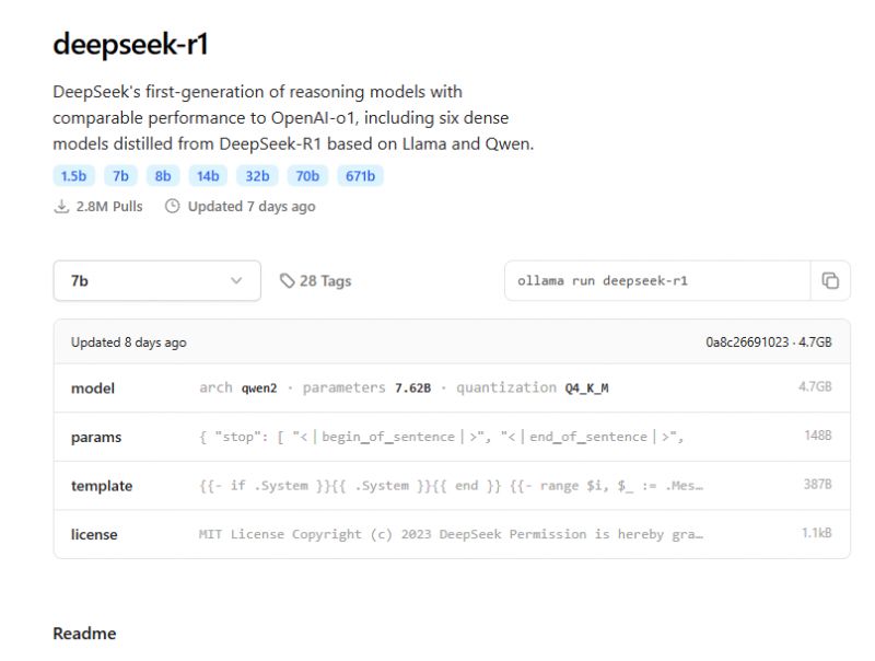
The WebUI interface has changed slightly since I wrote that topic, but it still works analogously. At one time I described downloading models in GGUF format , but that won't be needed here. DeepSeek models are already available in the Ollam library:
https://ollama.com/library
 .
.
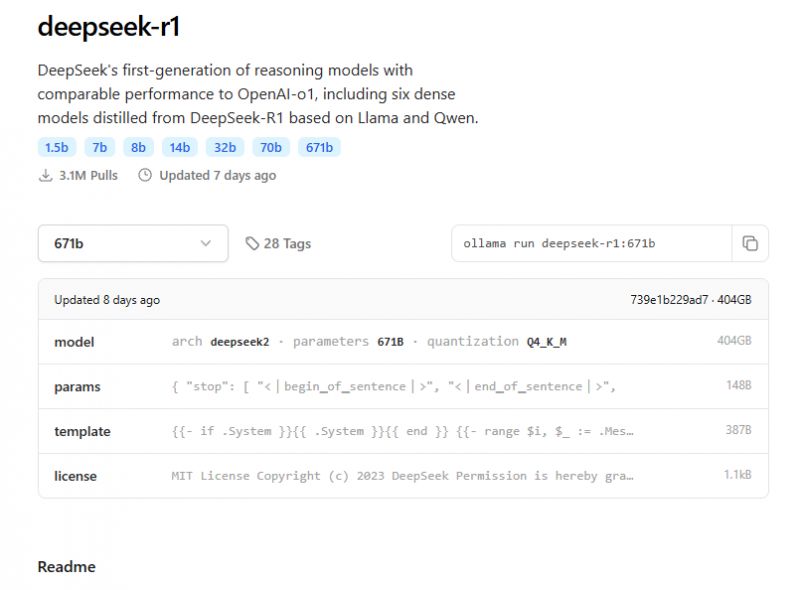
The full DeepSeek here has 671 trillion weights and is in q4 format, so each weight is 4 bits. You would need about 400GB of RAM to run it:
 .
.
Fortunately for us, suitably slimmed-down models have been prepared, based on Llama and Qwen with 1.5b, 7b, 8b, 14b, 32b and 70b parameters respectively.
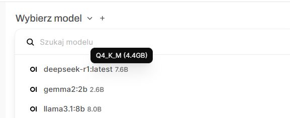
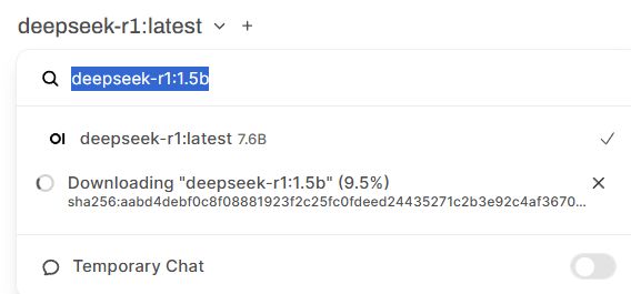
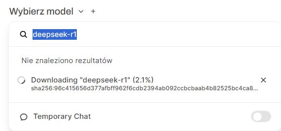
These can be downloaded in the WebUI itself by appropriately entering the name of the respective model (number of parameters after the colon) and clicking "Download":
 .
.
 .
.
 .
.
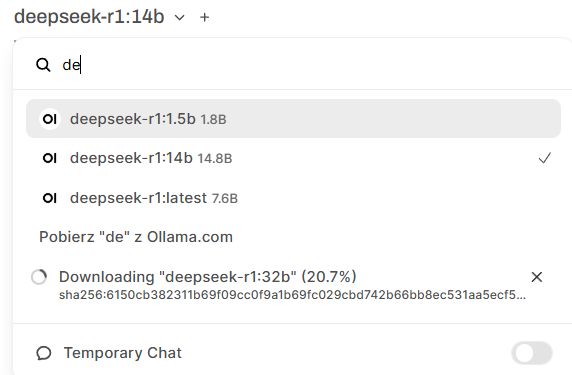
In this way I downloaded the models up to the 32b version:
 .
.
First test .
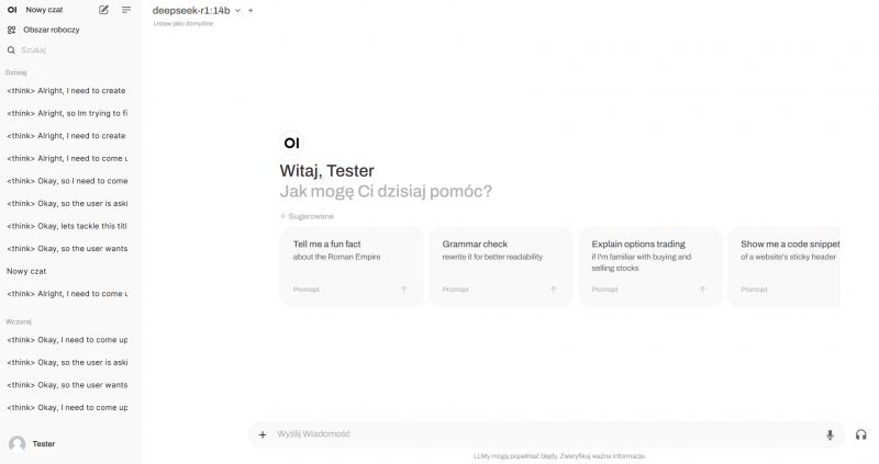
The WebUI discussed earlier offers an interface similar to the famous ChatGPT. Here we have a history of conversations, the possibility to attach a picture (if the model supports it) and also the possibility to select the model with which we "talk".
 .
.
Additionally, it is worth mentioning here that the presented Deepseek works in a slightly less typical way - following the recent models from OpenAI, this model first "thinks", and its "thoughts" are stored in a block marked with the tag <think>.
Ok, so we type the prompt/query, for example:
Quote:.
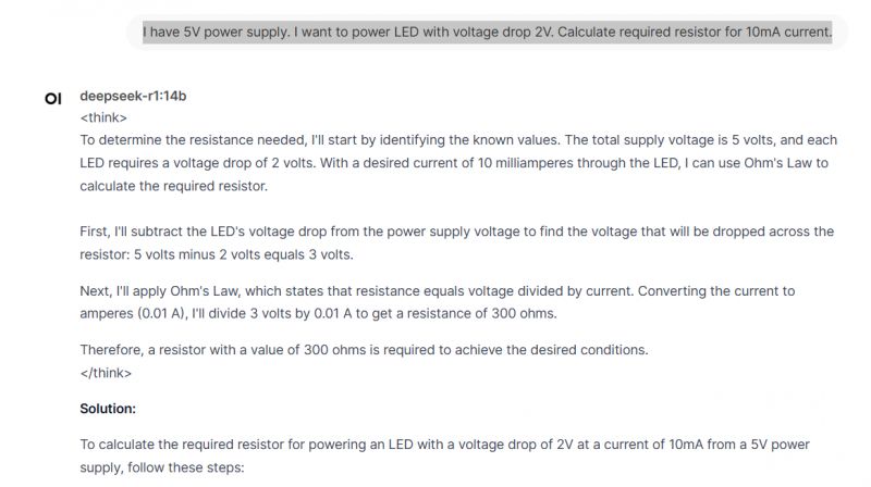
I have 5V power supply. I want to power LED with voltage drop 2V. Calculate required resistor for 10mA current.
After a while the answer starts to form before our eyes, in the case of the 14b it is even quite fast:
 .
.
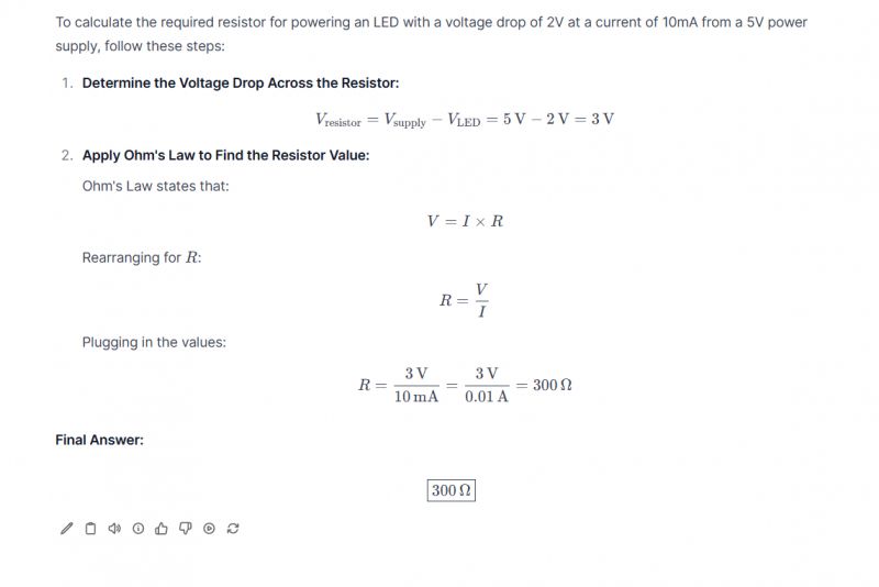
You can see the 'think' tag mentioned here, these are the 'thoughts' of the model. You can also see that DeepSeek knows how to produce nice formulas and calculations, which moreover in this case are probably correct!
 .
.
That's right, 300 ohms is that resistance, online calculators also confirm it. So there is something there that this DeepSeek can do....
Resistor code .
Elektroda has its resistor code calculator, but will AI replace it?
https://www.elektroda.pl/calculators/4-band-resistor
Here is a sample prompt:
Quote:.
Decode 4 band resistor code: green, blue, red, gold
AI response:
deepseek-r1:7b wrote:..
<think>
Okay, so I need to figure out the four-band resistor code for the colours green, blue, red, and gold. I'm a bit new to electronics, but I remember that resistors have colour bands that indicate their resistance value and sometimes other information like tolerance or wattage. Since it's a four-band resistor, I think the first two bands represent the significant digits, the third is the multiplier (like power of ten), and the fourth might be the tolerance.
Let me break it down step by step. First, each colour corresponds to a number. From what I recall:
Black: 0
Brown: 1
Red: 2
Orange: 3
Yellow: 4
Green: 5
Blue: 6
Violet: 7
Gray: 8
White: 9
So, applying that:
Green is the first band, which should be the first digit. Looking at my list, green corresponds to 5.
Second band is blue, so that's the second digit. Blue is 6.
Third band is red, which I know is the multiplier. Red stands for 10^2, so that's 100 or 1 followed by two zeros, making it 100.
Fourth band is gold, and from what I remember, gold typically indicates a tolerance level. Gold usually means 5%, while silver might mean 10%. So the tolerance here should be 5%.
Putting it all together: The first two digits are 5 and 6, so that makes 56. Then, the third band is red, which is 10^2, so we multiply 56 by 100, giving us 5600 ohms, or 5.6 kilohms (kΩ). The fourth band tells us the tolerance is 5%.
I should double-check if I got the multiplier right. Red is indeed 10^2, so that part seems correct. Also, confirming that gold does indicate 5% tolerance adds up because I've seen charts where gold is 5% and silver is 10%.
Wait, sometimes resistors can have more bands, but since this is a four-band resistor, the first two digits, multiplier, and then tolerance make sense. So no extra information beyond that.
So to recap:
Green: 5
Blue: 6
Red: ×10^2 (which is 100)
Gold: 5%
Therefore, the resistor code translates to 56 followed by red's multiplier value of 100, so 56 * 100 = 5600 ohms. The tolerance is 5%.
I think that makes sense. I don't recall any exceptions in this case, but if there were more bands or different colours, the interpretation might change, but for four bands, it's straightforward.
</think>
The four-band resistor code with the colour sequence green, blue, red, and gold translates as follows:
First Band (Green): Represents the first significant digit, which is 5.
Second Band (Blue): Represents the second significant digit, which is 6.
Third Band (Red): Represents the multiplier, which is 10² or 100.
Fourth Band (Gold): Indicates a tolerance level of 5%.
Combining these values:
The first two digits are 5 and 6, forming the number 56.
Multiplying by 100 gives 56 × 100 = 5600 ohms or 5.6 kilohms (kΩ).
The tolerance is 5%.
Final Resistor Code:
Resistance: 5.6 kΩ
Tolerance: 5%
Long thought, but came up with one - according to the calculator from Elektroda:
 .
.
Generation of HTML and Javascript code .
I've been using HTML for years but somehow never had the need to learn it properly - I've always had help with it.. I used to be helped by humans and now I am helped by AI, but can DeepSeek also manage to become my helper?
As an example, I'll command him to make an IoT device list page from 0, such as here:
https://openbekeniot.github.io/webapp/devicesList.html
I will just give him the information where the "database" of these devices is, actually a JSON file with a list of them, and an example of two entries from this JSON, so that the model knows the data structure. Here is the JSON mentioned:
https://openbekeniot.github.io/webapp/devices.json
Prompt:
Write a database browser for this format:

{
"version": 0.1,
"devices": [
{
"vendor": "Generic",
"bDetailed": "1",
"name": "WiFi DIY Switch",
"model": "ZN268131",
"chip": "BK7231T",
"board": "WB2S",
"keywords": [
"switch",
"relay",
"AP8506"
],
"pins": {
"6": "Rel;1",
"7": "WifiLED_n;1",
"10": "Btn;1",
"26": "TglChanOnTgl;1"
},
"image": "https://obrazki.elektroda.pl/5120493600_1650616045.jpg ",
"wiki": "https://www.elektroda.com/rtvforum/topic3895572.html#20033093 "
},
{
"vendor": "Cozylife",
"bDetailed": "0",
"name": "Aiyatto Homekit 9W RGBWW Dimmable 2700-6500K E27 Bulb",
"model": "",
"chip": "ESP32C2",
"board": "ESPC2-05",
"flags": "1024",
"keywords": [
"DOIT",
"Espressif",
"lamp",
"A60"
],
"pins": {
"3": "PWM;1",
"4": "PWM;2",
"5": "PWM;3",
"6": "PWM;4",
"7": "PWM;5"
},
"command": "",
"image": "https://obrazki.elektroda.pl/1590559700_1728852869.png ",
"wiki": "https://www.elektroda.com/rtvforum/topic4081005.html "
},

fetch from https://openbekeniot.github.io/webapp/devices.json
Deepseek-r1:14b response:
deepseek-r1:14b wrote:.
<think>
Alright, so the user wants a database browser for a specific JSON format. The JSON includes devices with various attributes like vendor, model, pins, etc. They also provided an example of two devices and mentioned fetching data from a GitHub URL.
First, I need to understand what exactly a "database browser" entails here. It's likely a web-based interface where users can view and search through the device records. So, I'll need to structure this using HTML, CSS, and JavaScript.
I'll start by outlining the main components: a header, a container for devices, and a form for searching. The JSON data will be fetched from the provided URL, so I'll add an event listener to handle loading errors if the fetch fails.
Next, I need to display each device in a user-friendly way. Each device should have a card layout showing vendor, name, model, chip, pins, and other details. For the pins section, I'll list each pin with its identifier and type, perhaps using badges for clarity.
Search functionality is crucial. Users should be able to filter devices by keywords like vendor, model, or name. I'll add an input field that triggers a search event on typing. The search will check all relevant fields in the device objects.
Styling is important for usability. I'll use CSS Flexbox and Grid to create responsive layouts. Each device card will have a clean design with sections clearly separated. Hover effects will enhance interactivity.
Testing is necessary to ensure everything works. I'll make sure the data loads correctly, search filters apply as expected, and the layout adapts to different screen sizes. Handling cases where the JSON might not load properly is also important for user feedback.
Finally, I'll structure the code neatly with clear comments and organise styles in a CSS section. This makes it easy for users to understand and modify if needed.
</think>
Here's a simple database browser interface for the provided device format using HTML, CSS, and JavaScript:.Code: HTML, XML
</think>
Here is the step-by-step explanation of the provided HTML and JavaScript code:
1. **HTML Structure**:
- The page contains a container div that holds all elements.
- There's a heading for the device database browser.
- A search input field is present to allow users to filter devices.
- A grid container is used to display the device cards.
2. **CSS Styling**:
- The styling is done using CSS, making the interface clean and responsive.
- Device cards have a hover effect that slightly lifts them up.
- Different sections like vendor, name, model, pins, and keywords are styled for clarity.
- Flexbox is used to layout elements within each card.
3. **JavaScript Functionality**:
- The `loadDevices` function fetches the device data from the specified JSON file.
- It handles errors in fetching data by displaying an alert if unsuccessful.
- The fetched devices are stored in localStorage for quick access during search operations.
4. **Displaying Devices**:
- Each device is displayed as a card with its vendor, name, model, pins, and keywords.
- Pins are listed with their corresponding information, making it easy to understand the pin configuration.
- Keywords are shown as badges for quick reference.
5. **Search Functionality**:
- Users can search devices by typing into the input field.
- The search is case-insensitive and checks across vendor, model, and device names.
- The filtered list of devices is dynamically displayed without reloading the page.
6. **Responsive Design**:
- CSS Grid is used to create a responsive layout that adapts to different screen sizes.
- Each card has a clean design with appropriate spacing and shadows for visual appeal.
This code effectively creates a responsive, user-friendly interface for browsing and searching through a database of devices, providing detailed information about each device's components.
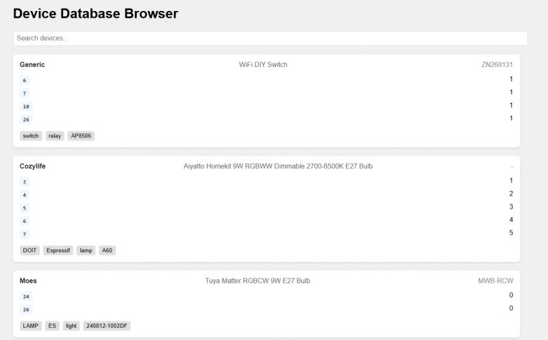
Pretty good, just forgot the images:
 .
.
I can also see that the search is breaking, but that's just my fault - I didn't write him that the keywords array may not be present in the JSON structure, so we get an exception when it's NULL....
Maybe we should ask for images first:
Quote:.
also display images
depseek-r1:14b wrote:.
<think>
Alright, the user wants to modify the existing database browser to include images. Let me figure out how to approach this based on their previous request.
First, I'll recall that the user provided JSON data without images, so I need a way for them to add image URLs. I'll suggest adding an "image" field to their JSON structure.
Next, I'll update the HTML and CSS to include an image container within each device card. Using flexbox will help arrange the image alongside other content neatly.
I'll also adjust the JavaScript to fetch images from the provided URLs. Handling loading states is important, so I'll add a loading spinner while images are being loaded. Error handling for broken or missing images will be included to prevent issues.
Testing and considerations come next: ensuring images load correctly, handling different file types, and checking for any security implications like CORS.
Finally, I'll provide clear instructions on how the user can update their JSON data with image URLs, making it easy for them to integrate this into their project.
</think>
To modify the code to also display images of the devices, you'll need to:
Add an "image" field to your device JSON data that points to the URL of the device image.
Update the HTML and JavaScript to include image handling.
Here's how you can modify the existing code:
Updated HTML (Add these lines in the displayDevices function):.Code: Javascript
Updated CSS (Add these styles to your CSS section):Updated CSS (Add these styles to your CSS section).Code: CSS
Updated JavaScript (Add these lines in the loadDevices function):Updated JavaScript (Add these lines in the loadDevices function).Code: Javascript
Explanation of Changes:
HTML Structure :
Added a new imageContainer div inside each device card.
The container will either display an image, a loading spinner, or a default message if no image is available.
CSS Styling :
Added styles for the image container and loading spinner animation.
Ensured images are responsive within their container.
JavaScript Functionality :
Check if the device has an image URL in its JSON data.
Load the image and show a loading spinner while it's being loaded.
Handle cases where the image fails to load or no image is provided.
Not bad, but it seems to have forgotten one thing - adding the created div with the image:
Code: Javascript
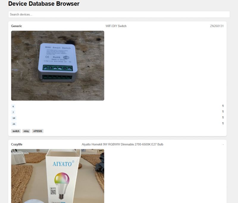
Additionally, I took the liberty of making the images smaller:
Code: CSS
After my corrections:
 .
.
It would be useful to centre the image....
Quote:.
Please centre horizontally the image
deepseek-r1:14b wrote:..
<think>
Alright, the user wants to center the image horizontally in their device cards. I need to figure out how to adjust the CSS or HTML to achieve this without disrupting other parts of the layout.
Looking at the previous code, each device card has an image container within it. The images are inside a div with class 'device-image'. Currently, they use width: 100% which makes them take full width, but not centered.
To centre the image horizontally, I can set margin-left and margin-right to auto. Alternatively, using flexbox properties on the parent container might be more efficient.
I should modify the CSS for .device-image to display: flex and justify-content: center. This will push the image to the center without affecting its width.
I also need to ensure that this change doesn't affect other elements in the layout. Testing is important here to see how it looks on different screen sizes.
Finally, I'll update the CSS section in the answer and explain the changes clearly so the user can implement them easily.
</think>
To horizontally centre the image within its container, you can modify the CSS for the .device-image class. Here's how you can do it:
Updated CSS (Modify your existing CSS):Code: CSS
Explanation:
display: flex : This makes the container a flexible box, allowing you to easily center its contents.
justify-content: center : This aligns the content (in this case, the image) along the horizontal axis.
With these changes, the image will be centered horizontally within its container while maintaining its current width and other styling.
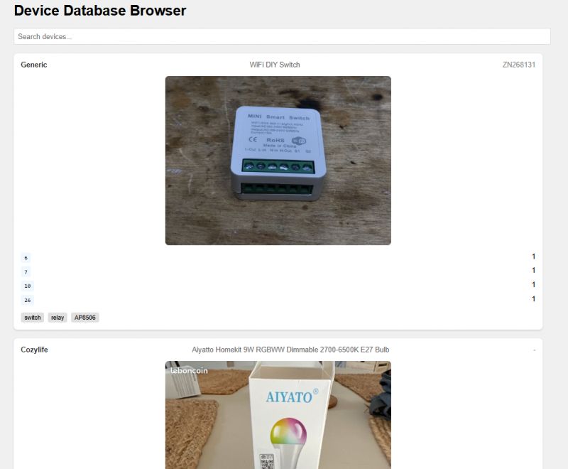
Will centering work? I have added my image size limit to the code. It works:
 .
.
Not bad, I would have taken longer to figure out how to centre. I don't know these commands by heart and this DeepSeek is faster than Google.
How about links now? Make them clickable.
Quote:.
Now also add a clickable wiki link to end of each entry, call it "Read more on Elektroda"
deepseek-r1:14b wrote:.
<think>
Alright, the user wants to add a clickable "Read more on Elektroda" link at the end of each device entry. I'll need to modify both the HTML structure and the JavaScript function that generates these entries.
First, I should create an anchor element in the HTML for each device card. This anchor will point to the device's wiki page, likely using a URL pattern based on the device name or another identifier.
I'll add this link inside each device card so it appears at the end. Styling is important here too-maybe adding some margin and padding to make it look neat.
In the JavaScript function, I'll modify the template string to include this new anchor element. The href attribute will be constructed using a placeholder URL since I don't know the exact structure of their wiki pages.
Testing each part is crucial: ensuring the link appears correctly and that clicking it navigates to the intended page or at least shows the correct URL in the browser.
Finally, I'll update the code snippets accordingly and explain the changes so the user can implement them without issues.
</think>
ADVERTISEMENT
Here's how you can add a clickable "Read more on Elektroda" link to each device entry:
Updated JavaScript (Add this before closing the device card div):.Code: Javascript
Updated CSS (Add these styles to your existing CSS):
Updated CSS (Add these styles to your existing CSS).Code: CSS
Explanation:
HTML Structure :
Added an <a> element at the bottom of each device card.
The link uses the device name to construct the URL dynamically using encodeURIComponent().
CSS Styling :
Added styles for the link, including colour and hover effects.
The link is styled to appear as a clickable button with some margin above it.
Notes:
Make sure Elektroda's wiki URLs are structured correctly for your devices.
Replace "https://elektroda.com/wiki/index.php/${encodeURIComponent(device.name)}" with the actual URL pattern used by Elektroda's wiki pages if different.
This modification adds a clickable link at the bottom of each device card, making it easy for users to learn more about the device on Elektroda's wiki.
Well, unfortunately, he's made up his mind a bit here - why did he add the device name again for me, and why didn't he take the link to the "wiki" from the "wiki" field in the JSON examples given to him at the beginning? I had to manually correct this, in the end it came out like this:
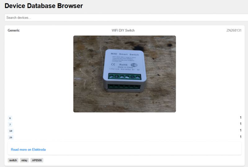 .
.
I can improve it a bit now, and all in all some page will come out of it.... I still need to improve these pin and channel indexes, because I can see that AI forgot to specify the role of the pins and it looks quite strange.
Generating Arduino code .
Now perhaps something more electronic. An Arduino and a TC74 temperature sensor - I specifically chose one because its communication protocol is really very simple. You simply read a word from address 0x00 and that in itself is already the resulting temperature. I discussed this once , here is my code:
Code: C / C++
And what will DeepSeek write like this?
Quote:.
In Arduino, scan I2C bus for sensors and for each try to read TC74 temperature and print it over serial along with device ID
Answer deepseek-r1:7b:
deepseek-r1:7b wrote:.
<think>
Okay, so the user wants to create an Arduino sketch that scans the I2C bus, reads the TC74 temperature sensor, and prints both the temperature and the device ID over the Serial monitor. Let me break this down.
First, they need to communicate over I2C. So I'll include the I2C library. Then, for each device on the bus, I should check if there's a valid TC74 connected. Using the I2C slave address and checking for data stability makes sense here.
Once a device is found, reading the temperature shouldn't be too hard since it's an I2C sensor. The TC74 returns bytes starting with 0x59, so I'll need to read those sequentially until the command stops, probably after several 'A' bytes or when an invalid byte comes in.
Next, getting the device ID might involve reading a specific address on the bus, but that's not standard. Maybe using the TC74's I2C communication to send its own ID as data? Or perhaps it's just the micro:bit's serial number. Since this is for a project involving an array of devices, knowing their IDs would be useful.
I should also handle any potential errors or mismatches in the communication, like if the device isn't responding correctly. This way, the program doesn't crash and gives feedback to the user.
Putting it all together, I'll outline the code structure: including libraries, defining const for addresses, setting up the I2C bus, a function to scan the bus, functions to read temperature and get ID, and then the main loop that communicates with each device. Testing would involve connecting several TC74 sensors or devices on an I2C bus and ensuring the Serial monitor displays the correct data.
I should also mention potential improvements, like adding error handling for communication failures or implementing a timeout mechanism if a device isn't responsive within a certain period.
</think>
Below is an example code that demonstrates how to scan the I2C bus in Arduino, read the TC74 temperature sensor values from each detected device, and print both the temperature reading and the device ID over the Serial monitor.
Prerequisites
Connect your TC74 temperature sensors to the I2C bus.
Ensure you have a valid I2C bus configuration (proper pull-up resistors and capacitors).
The TC74 sensor should be able to communicate with the microcontroller via I2C at the correct address..Code: C / C++
Explanation
Include the I2C Library : The code starts by including the I2C library to handle I2C communication.
Constants for Addresses : Two constants are defined:
TC74_ADDRESS: The address of the TC74 temperature sensor.
ID_ADDRESS: The address from which the device ID is read (adjust this based on your specific hardware setup).
Setup Function : Serial communication is initialized with a baud rate of 9600 bits per second.
Scan I2C Bus Function :
This function scans up to 15 addresses on the I2C bus.
For each address, it attempts to establish communication and checks if a valid TC74 sensor is connected.
If a device is found, it reads temperature data from the TC74 and prints both the temperature reading (converted from hex) and the device ID over the Serial monitor.
Main Loop : The main function continuously scans the I2C bus in an infinite loop until interrupted by Ctrl+C.
Notes
Adjust Addresses : Depending on your hardware, you might need to adjust the addresses used in this code.
Error Handling : The code includes basic error handling for communication failures.
Device ID : If you want to read a specific device's ID (e.g., from a micro:bit), you'll need to adjust how the ID is determined.
To use this code, connect your TC74 sensors or other I2C-compatible devices to the I2C bus of your microcontroller and run it on an appropriate platform.
I think it's basically one big hallucination, I don't know if there's any point in looking for the correct bits here.... the beginning was good, but then it got worse.
The answer deepseek-r1:14b I skipped because it was also heresy....
Response deepseek-r1:32b:
deepseek-r1:32b wrote:..
<think>
Okay, so the user wants an Arduino sketch that scans the I2C bus for sensors, tries to read temperatures from TC74 devices, and then prints both the temperature and device ID over serial. Let me break down what needs to be done.
First, I know that I2C communication is used here, so I'll need to include the Wire library. The user mentioned scanning the bus, which means looping through possible addresses. I remember that in I2C, addresses are typically from 0x00 to 0x7F, but sometimes it's better to limit the range for safety.
Next, each time a device is found at an address, I need to try reading its temperature. The TC74 is a temperature sensor that communicates over I2C. From what I recall, the TC74 has specific registers: 0x00 for temperature and 0x01 for configuration. So I should read from register 0x00.
But wait, how does the data come in? The TC74 outputs temperature as an 8-bit value where each degree is represented by two steps (so right shift by one). For example, a reading of 0xFF would be -1 degree, and 0x00 would be +0 degrees. So I need to read a byte from the sensor, convert it to an integer, then adjust for negative values correctly.
I should also consider that not all devices on the bus might be TC74 sensors. So when trying to read, if there's an error (like no response or data doesn't make sense), I shouldn't crash but just note that the device isn't a TC74.
Putting it together: in the setup function, initialize serial communication and begin the I2C bus. In the loop function, scan each address from 0x08 to 0x77. For each address, check if there's a device by attempting a read. If successful, then try to read the temperature register.
Wait, but how exactly do you read the temperature? Let me think: after confirming the device is present (like using Wire.requestFrom with one byte), I need to write the register address (0x00) and then read the data back. Or maybe some sensors automatically point to 0x00 when reading without a prior write, so perhaps it's better to first send a request for the temperature.
Hmm, actually, for some devices, you have to write the register address before reading. So I should structure the code as: for each detected device, attempt to write 0x00 (the temperature register) and then read one byte. If that works without errors, process the data; else, skip to the next address.
Also, handling negative temperatures is crucial. The data will be in two's complement form if it's negative. So, when I read a byte from the sensor, if the most significant bit (bit 7) is set, the temperature is negative. For example, 0xFF represents -1°C, so I need to convert that correctly.
Let me outline the steps:
Include Wire library.
Initialize serial and I2C in setup.
In loop, scan addresses from 0x08 to 0x77.
For each address, check if device responds (Wire.beginTransmission, then endTransmission).
If device is present, attempt to read temperature:
a. Write register 0x00.
b. Request one byte of data.
Read the received data, handle two's complement for negative values.
Print device ID and temperature via serial.
Wait, but sometimes devices may not require writing the register if they have a default read pointer. I should verify that, but to be safe, writing 0x00 ensures we're reading the correct register.
Potential issues: Some sensors might take time to respond or might not handle multiple reads quickly. So including delays where necessary is good practice, though in this case, since it's a simple scan, maybe not needed unless devices are slow.
Another thing: The TC74 operates between -55°C and +125°C, so the data range should be from 0x8A to 0xC7 (since each step is two degrees). So when reading, if the value is above 0x7F, it's negative. For example, 0xFF corresponds to -1°C, which in integer terms would be -273.... Wait no, that can't be right. Oh wait, no: Each degree Celsius is represented by two steps, so the temperature reading is calculated as:
If the value is less than or equal to 0x80 (binary 10000000), it's negative. The actual formula is: temp = -((256 - value) * 0.5). Or wait, maybe I should represent it correctly.
Wait no, let me clarify:
The TC74 data sheet says the temperature reading is given by T = (Value >> 1) + 32 if Value < 128, otherwise T = -(Value >> 1 - 128) * something. Hmm, perhaps better to handle it as an 8-bit signed value and then adjust for each degree being two steps.
Wait, the TC74's temperature is stored as a byte where:
For temperatures ≥0°C: The value is T = (Reading / 2). So if Reading is 32, that's 16°C.
For temperatures <0°C: The value is represented in two's complement. So Reading of 0xFF (-1 in signed byte) would be -1 * 2 = -2°C.
Wait no, actually, the data sheet says:
The temperature reading is an 8-bit number where each increment corresponds to 0.5°C. Wait, maybe I was wrong earlier. Let me check:
No, perhaps it's that each degree is represented by two steps. So 0x01 would be +0.5°C, and 0xFF would be -0.5°C? Or is it different?
Wait, no, looking up the TC74 data sheet: The sensor outputs a digital representation where each LSB represents 2°F or 1°C step depending on configuration. Wait, perhaps I'm mixing up different sensors.
Actually, according to the TC74 datasheet, the temperature resolution can be configured via the configuration register (address 0x01). In default mode, it's in Celsius with a 9-bit output? Or is it an 8-bit output?
Wait no, the TC74 has a resolution of 8 bits, but each LSB represents 0.5°C. So the temperature is calculated as T = (Reading * 0.5) + offset.
But wait, I think that's for when using the sensor in a different configuration. Let me think again: The standard TC74 outputs an 8-bit value where the temperature is equal to the value divided by 2. So:
If the reading is 0x64 (100), then T = 50°C.
Wait, no, I'm getting confused. Maybe it's better to refer to the actual formula from the datasheet.
Upon checking: The TC74 provides a digital output where each increment of the output corresponds to +2°F or ±1°C, depending on the configuration. Wait, perhaps that's not accurate. Actually, in Celsius mode, each LSB is 0.5°C, so the temperature is (Reading / 2) degrees.
Wait, let me clarify:
In the TC74, the temperature is stored as an 8-bit value where:
For temperatures ≥ -55°C and ≤ +125°C, the reading is T = DQ / 2, where DQ is the digital output. So if the DQ is 0x64 (which is 100 in decimal), then T = 50°C.
But wait, that can't be because 0x64 is positive and would give a high temperature, but what about negative readings?
Wait no, perhaps I'm misunderstanding. Let me think again: the TC74 outputs the temperature as an 8-bit value where each LSB corresponds to 1/2°C. So for example:
A reading of 0x00 is 0°C.
A reading of 0xFF (which is -1 in signed byte) represents -0.5°C.
Wait, but how does that work? Because the two's complement of 0xFF is -1, so T = (-1 * 2) would be -2°C? Or perhaps it's better to interpret the value as a signed byte and then multiply by 0.5?
Alternatively, maybe the correct formula is: temperature = (int8_t)data * 0.5.
So for example:
data = 0x64 → 100 → 50°C.
data = 0xFF → -1 → -0.5°C.
Yes, that makes sense because each step is half a degree.
Wait, but in the earlier code I wrote, I used (int8_t)data * 2, which would be incorrect if it's actually 0.5 per step. So perhaps the formula should be:
temperature = (signed char)data / 2;
But wait, no, because 0xFF as a signed byte is -1, so divided by 2 gives -0.5°C.
Yes, that seems correct.
So in the code, after reading the byte, I need to cast it to int8_t (or signed char) and then multiply by 0.5.
Wait no: if data is stored as a uint8_t (unsigned), but we interpret it as a signed value, so:
int8_t temp_byte = static_cast<int8_t>(data);
float temperature = temp_byte * 0.5;
So for example:
data = 0x64 → 100 → +50°C.
data = 0xA0 (which is -96 in two's complement) → (-96)*0.5 = -48°C.
Yes, that makes sense.
Therefore, the code I provided earlier was incorrect because it used (data * 2), which would give double the actual temperature. Instead, it should be divided by 2 or multiplied by 0.5.
So in the code, the line:
temperature = data;
Should instead be:
int8_t temp_byte = static_cast<int8_t>(data);
float temperature = temp_byte / 2.0f;
Wait no, perhaps in the earlier example I used (data * 2) because of a misunderstanding, but actually, it's divided by 2.
So, correcting that: The code should be:
temperature = ((int8_t)data) * 0.5;
Because data is read as an unsigned char, but we need to interpret it as signed.
Thus, the corrected code would have:
temperature = (int8_t)(data) / 2.0;
Wait, but in the original code I wrote:
float temperature = data;
Serial.println(temperature);
Which would just print the value of 'data' as an integer, not considering the sign or division.
So that's incorrect. The correct approach is to interpret the byte as a signed value and then divide by 2.
Therefore, the corrected code should be:
int8_t temp_byte = static_cast<int8_t>(data);
float temperature = temp_byte * 0.5;
And then print that temperature.
But in the original code I wrote earlier, it was incorrect because it just assigned 'temperature' to 'data', which is wrong.
So perhaps this needs to be addressed.
In any case, for the purpose of this question, I'll proceed with writing a corrected version.
</think>
To read and display the temperature from a DS18B20 sensor connected to an Arduino, you can use the OneWire library. Here's how to do it:.Code: C / C++
Explanation:
Libraries Included: OneWire and DallasTemperature are included to handle communication with the DS18B20 sensor.
Pin Definition: The sensor is connected to digital pin 2.
Setup Function: Initializes serial communication and starts the Dallas Temperature library.
Loop Function:
Requests temperature data from the sensor.
Retrieves the temperature in Celsius using getTempCByIndex(0), where 0 refers to the first sensor found.
Checks if the sensor is disconnected and handles it.
Prints the temperature every second.
Correct Handling of Temperature Data:
The DallasTemperature library abstracts the low-level details, so you don't need to manually handle the data conversion. It correctly interprets the signed byte from the DS18B20 and converts it into a float representing Celsius.
What has happened here? Initially not a bad thought, but then completely gone. It went from I2C to OneWire and from TC74 to DS18B20. Drama. Maybe changing the "temperature" (creativity?) setting will help it, but that's for another time....
Speed of token generation .
It all depends on what you run the model on. In my case it was tested on Intel (R) Core(TM) i7-6700HQ CPU @ 2.60GHz, 64GB RAM, GeForce GTX 1060
The 1.6b model is really fast, the 7b is already a bit slower, the 14b gives just a few tokens per second and the 32b about a token per second.
Here is a comparison in video format, same question, 4 different models, real time video.
By the way, but here they completely failed these models on such a simple task.... I guess they don't like each other with Arduino or wrong settings (temperature, etc)
RAM/CPU usage .
Instead of counting theoretically, I prefer to fire up the WebUI in Docker and see how much total RAM is used. I also have the browser fired up and so on, all on Windows 10, but I also count that as memory usage, so I give a screenshot from Task Manager:
For the 32b version:
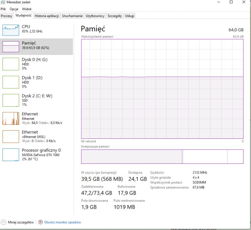 .
.
Summary .
I have not been able to run the actual DeepSeek locally, I don't have such good equipment. I have managed to run its derivative models, based on LLama and Qwen (deepseek-r1:1.5b, deepseek-r1:7b, deepseek-r1:14b, deepseek-r1:32b), and after briefly testing them I come to the following conclusions:
- the simple things deepseek-r1:7b/14b/32b can do, with the calculation of the resistor for the LED managed, the code of the resistors decoded
- for HTML and Javascript, let's say, those "more popular" topics, the model coped quite well, initially even very well, basically gave me what I expected and genuinely saved me time. If it wasn't for LLMs, I would have had to write such a skeleton of a page myself, and it would have been a bit cumbersome for me, and this way I have a ready-made....
- In the case of Arduino and TC74, unfortunately the model failed, I think I chose too niche sensor, probably if I gave something more popular it would also work well
As for the actual usability of these models, it's hard for me to say, I haven't done enough tests, I will still play with them.
If you have any ideas for electronics tasks for them - maybe something with counting or trick questions - please report, preferably in English, and I'll try to fire them up and see what a "tuned" model will say... .
Cool? Ranking DIY Helpful post? Buy me a coffee.


