logo elektroda
logo elektroda
X
logo elektroda

[BK7231N/CB2S/BL0937] Wifi Smart Plug with Energy Measurement (RMC021)

Raufaser 8745 47
ADVERTISEMENT
  • Helpful post
    #1 20991558
    Raufaser
    Level 10  
    [BK7231N/CB2S/BL0937] Wifi Smart Plug with Energy Measurement (RMC021)

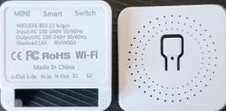
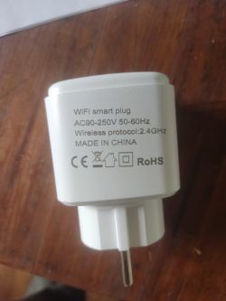
    I bought this smart plug for very cheap in a big chinese online warehouse.
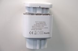
    Close-up of the back of a Wi-Fi smart plug with technical details and certifications.

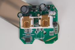
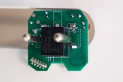
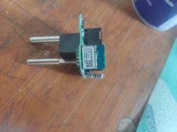
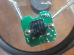
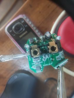
    I disassembled it and figures out it has a BK7231N / CB2S chip. And a BL0937 for energy measurement.
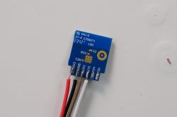
    I tried to commuincate with the CB2S still in place. But it turned out that the switch and some stuff interfered with the RX path. I didn't want to cut any path so i desoldered the whole CB2S. Flashed it seperately. And but everything back together.
    I flashed the version 1.17.493 with Easy UART Flasher.
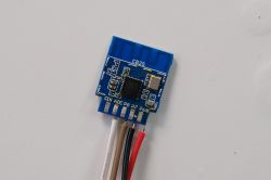
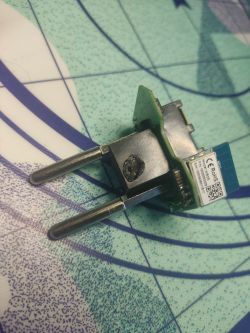
    CB2S module with connected wires Close-up of a blue electronic module with attached wires. View of a smart plug circuit board with electronic components. Close-up of the internal components of a smart plug with a visible integrated circuit.

    I also dumped the orignial firmware. readResult...-39-15.zip Download (1.06 MB)

    Here is the extracted config from the original firmware

    {
    	"sel_pin_pin":"24",
    	"rl1_lv":"1",
    	"bt1_pin":"10",
    	"net_trig":"2",
    	"jv":"1.0.5",
    	"netled1_lv":"0",
    	"netled_reuse":"1",
    	"bt1_type":"0",
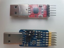
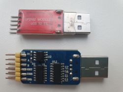
    	"ffc_select":"0",
    	"vi_pin":"6",
    	"resistor":"1",
    	"over_cur":"17000",
    	"bt1_lv":"0",
    	"reset_t":"3",
    	"netled1_pin":"8",
    	"chip_type":"0",
    	"lose_vol":"80",
    	"over_vol":"280",
    	"module":"CB2S",
    	"ele_pin":"7",
    	"ch_cddpid1":"9",
    	"ch1_stat":"2",
    	"rl1_type":"0",
    	"ch_num":"1",
    	"ele_fun_en":"1",
    	"rl1_pin":"26",
    	"vol_def":"0",
    	"ch_dpid1":"1",
    	"sel_pin_lv":"1",
    	"crc":"7",
    	"bv":"40.00",
    	"pv":"2.2",
    	"lpv":"3.4",
    	"pk":"keyjup78v54myhan",
    	"firmk":"keyjup78v54myhan",
    	"cadv":"05",
    	"cdv":"1.0.0",
    	"dev_swv":"1.1.17",
    	"s_id":"null",
    	"dtp":"0",
    	"sync":"0",
    	"attr_num":"1",
    	"mst_tp_0":"9",
    	"mst_ver_0":"1.1.17",
    	"mst_tp_1":"0",
    	"mst_ver_1":"null",
    	"mst_md5_1":"null",
    	"mst_tp_2":"0",
    	"mst_ver_2":"null",
    	"mst_md5_2":"null",
    	"mst_tp_3":"0",
    	"mst_ver_3":"nul0abi",
    	"id":"bf847d9d9bcc6ef2ed0l2q",
    	"swv":"1.1.17",
    	"mtruer_0":"1.0.5",
    	"mst_md5_0":"febf39e119105090f91b2184eeda92cb",
    	"mst_md5_3":"null }de",
    	"property":"{min",
    	"max":"86400",
    	"scale":"0",
    	"step":"1",
    	"type":"value}"
    }


    Device configuration, as extracted from Tuya: 
    - BL0937 SEL on P24
    - Button (channel 1) on P10
    - BL0937 VI on P6
    - WiFi LED on P8
    - BL0937 ELE on P7
    - Relay (channel 1) on P26
    Device seems to be using CB2S module, which is using BK7231N.
    And the Tuya section starts, as usual, at 2023424


    I already setup OpenBeken to connect to my local wifi network and i was able to load the driver for the BL0937. Calibration for Voltage was no problem. I am not sure how to calibrate current and power without electrocuting myself ;) But so far my 60W heating bulb shows 60W and my 7.5W LED bulb shows 7.5W. So i guess it is accurate enough :)

    I ordered 3 more plugs from the chinese web warehouse for a total of 10€ ... I hope they are flashable too.

    Webapp JSON
    {
      "vendor": "Tuya",
      "bDetailed": "0",
      "name": "Wifi Smart Plug with Energy Measurement",
      "model": "RMC021",
      "chip": "BK7231N",
      "board": "CB2S",
      "flags": "1024",
      "keywords": [
        "power metering",
        "smart plug",
        "bl0937"
      ],
      "pins": {
        "6": "BL0937CF1;0",
        "7": "BL0937CF;0",
        "8": "WifiLED_n;0",
        "10": "Btn;1",
        "24": "BL0937SEL;0",
        "26": "Rel;1"
      },
      "command": "",
      "image": "https://obrazki.elektroda.pl/4143902500_1709667653.webp",
      "wiki": "https://www.elektroda.com/rtvforum/topic4040624.html"
    }
  • ADVERTISEMENT
  • #2 20991634
    p.kaczmarek2
    Moderator Smart Home
    Thank you for your submission. We have few sockets from RMC family on our list here:
    https://openbekeniot.github.io/webapp/devicesList.html
    but not yet the RMC021.

    Still, can you also include the OBK JSON template from the Web App?
    Helpful post? Buy me a coffee.
  • #3 20991901
    Raufaser
    Level 10  
    I did. I hope that is what you meant.
  • ADVERTISEMENT
  • #4 20992524
    Raufaser
    Level 10  

    Are all informations included needed to add it to the device list? Or is still something missing?
  • #5 20992590
    p.kaczmarek2
    Moderator Smart Home
    Well, you should fill the fields of image and the topic link, but I can do it myself as well. I will add the device in a moment.
    Helpful post? Buy me a coffee.
  • #6 21068306
    150219v8
    Level 2  

    Here you can see an easy way to open this kind of device.


  • ADVERTISEMENT
  • #7 21068364
    p.kaczmarek2
    Moderator Smart Home
    Opening LSPA9 plug with a door, that's a very unexpected but yet also interesting thing to see
    Helpful post? Buy me a coffee.
  • Helpful post
    #8 21092497
    12th23poiuzzz
    Level 4  

    Great job Raufaser!
    Works fine with the first of my 5 devices.
    I first tried this: https://www.brunweb.de/using-a-aldi-workzone-wifi-smart-socket-without-tuya-cloud/ with these settings:
    P6 (PWM0) -> BL0937CF1
    P7 (PWM1) -> BL0937CF
    P8 (PWM2) -> BL0937SEL
    P11 (TXD1) -> WifiLED (or another LED functionality as you wish)
    P24 (PWM4) -> Rel 0
    P26 (PWM5) -> Btn 0 0
    Although PCB looks the same without success.

    Only reading the original firmware did not work.

    BTW: I use Linux Mint. BK7231Flasher works fine using Mono: https://github.com/openshwprojects/BK7231GUIFlashTool
  • #9 21092515
    p.kaczmarek2
    Moderator Smart Home
    Can you share the template in JSON format, so we can add it here:
    https://openbekeniot.github.io/webapp/devicesList.html
    Is this image (from linked site) a correct image for your device?
    The image shows a smart Wi-Fi switch with labels and technical specifications.
    Helpful post? Buy me a coffee.
  • #10 21092556
    12th23poiuzzz
    Level 4  
    Short tut using Mint and 2104 FTDI-adapter

    - desolder the CB2S-Module
    - connect 4 pins:
    Rx-Rx
    Tx-Tx
    3V3-3V3
    GND-GND
    Find more: https://developer.tuya.com/en/docs/iot/cb2s-module-datasheet?id=Kafgfsa2aaypq

    - start BK7231Flasher.exe
    - set chiptype (BK 7231N) and firmware
    - set 921600 baud
    - find port using: sudo ls /dev/ttyUSB* in Mint terminal
    - set port
    - "Do firmware write (no backup) " with BK7231Flasher and follow the instructions. A backup of the original firmware did not work for me.

    Find and connect 7231s network and type http://192.168.4.1 in your browser (https did not work here). I did use my smartphone, Mint did not show the access.
    The OpenBK website should appear.
    Find "Execute custom command“ and enter: startDriver BL0937 to use the power monitoring feature.

    - configure Module:
    P6 - BL0937CF1
    P7 - BL0937CF
    P8 - WiFiLED
    P10- Button
    P24- BL0937SEL
    P26- Relay

    Configure WiFi, MQTT etc.
    Solder and screw and glue everything as it was.
    Then adjust your device with VoltageSet, CurrentSet, PowerSet and be happy.

    cu
  • #11 21092994
    p.kaczmarek2
    Moderator Smart Home
    12th23poiuzzz wrote:

    - "Do firmware write (no backup) " with BK7231Flasher and follow the instructions

    I would still suggest doing backup (firmware read, 2MB) first
    Helpful post? Buy me a coffee.
  • #12 21093250
    12th23poiuzzz
    Level 4  
    12th23poiuzzz wrote:
    Can you share the template in JSON format, so we can add it here:
    https://openbekeniot.github.io/webapp/devicesList.htmlIs this image (from linked site) a correct image for your device?


    Its not my site. So I can't provide the template. The author uses BK7231Flasher with its image, IMHO.

    Hinzugefügt nach 1 [Stunden] 11 [Minuten]:

    p.kaczmarek2 wrote:
    12th23poiuzzz wrote:

    - "Do firmware write (no backup) " with BK7231Flasher and follow the instructions

    I would still suggest doing backup (firmware read, 2MB) first


    A backup of the original firmware did not work for me:

    Backup name is set to aaaa.
    Starting read!
    Now is: Donnerstag, 23. Mai 2024 14:57:06.
    Flasher mode: BK7231N
    Going to open port: /dev/ttyUSB0.
    Serial port open!
    Getting bus... (now, please do reboot by CEN or by power off/on)
    Getting bus failed, will try again - 0/100!
    Getting bus success!
    Going to set baud rate setting (921600)!
    Will try to read device flash MID (for unprotect N):
    Flash MID loaded: 1560EB
    Will now search for Flash def in out database...
    Flash def found! For: 1560EB
    Flash information: mid: 1560EB, icName: TH25Q_16HB, manufacturer: TH, szMem: 1000000, szSR: 2, cwUnp: 0, cwEnp: 7, cwMsk: 407C, sb: 2, lb: 5, cwdRd: 05-35-FF-FF, cwdWr: 01-FF-FF-FF
    Entering SetProtectState(True)...
    sr: 0
    sr: 0
    final sr: 0
    msk: 407c
    cw: 0, sb: 2, lb: 5
    bfd: 0
    SetProtectState(True) success!
    Going to start reading at offset 0x00...
    Reading 0x00... failed with serial.BytesToRead 4073 (expected 4111)
    The beginning of buffer in UART contains 040EFF01E0FCF4061009000000200069 data.
    Failed! There was no result to save.
  • #13 21107616
    p.kaczmarek2
    Moderator Smart Home
    Backup process is using the same mechanics as the write process so it's very strange. I'd suggest just retrying. You can also play with timeout/retry settings in advanced tab.
    Helpful post? Buy me a coffee.
  • #14 21109164
    tun0
    Level 6  

    Out of curiosity: how did you manage to desolder the CB2S module? I tried to do so on 2 out of the 5 I ordered, and managed to lift at least one pad before getting any movement in the CB2S module. Tried adding flux, adding solder, solder sucker, solder wick and now running out of ideas. Even though these are darn cheap, ruining them still seems like a waste.
  • #15 21109289
    p.kaczmarek2
    Moderator Smart Home
    Well, I desoldered hundreds of CB2S/WB2S modules already. You can check out the process on one of our videos:


    Helpful post? Buy me a coffee.
  • #16 21109572
    tun0
    Level 6  

    The approach outlined in the video looks pretty similar to my attempts. My takeaways: lower the iron's temperature and perhaps buy a better quality solder wick. Which temperature do you tend to use?
  • #17 21126827
    tun0
    Level 6  
    Quick update: did manage to desolder a CB2S module from the socket the other day. However, I'm still struggling getting the flasher to see the device. Wondering if I either damaged the CB2S or perhaps my USB-to-UART dongle isn't suited (or broken). Guess I'll see if I can solder the CB2S back to the socket using wires safely, to see if it'd still work like that.
  • #18 21127144
    p.kaczmarek2
    Moderator Smart Home
    I'm trying to keep low temperature, on my KSGER I use 350C.

    How your flashing setup looks like?
    Helpful post? Buy me a coffee.
  • Helpful post
    #19 21135558
    gregmarfaing
    Level 6  
    I got a variant with a wb2s inside from aliexpress
    Electronic module of a smart plug from AliExpress on a wooden background. White smart plug with technical markings, lying on a wooden surface. Close-up of an electronic module with a JIEYING integrated circuit mounted on a green PCB, held by a metal tool. Close-up of a PCB with electronic components.

    It's a RMC-001 according to the manual
    and here is the template
    {
      "vendor": "Tuya",
      "bDetailed": "0",
      "name": "Generic smart plug ",
      "model": "RMC001",
      "chip": "BK7231T",
      "board": "WB2S",
      "flags": "1024",
      "keywords": [
        "Smart plug",
        "WB2S"
      ],
      "pins": {
        "6": "WifiLED_n;0",
        "7": "BL0937CF;0",
        "8": "BL0937CF1;0",
        "10": "Btn;1",
        "24": "BL0937SEL;0",
        "26": "Rel;1"
      },
      "command": "",
      "image": "https://obrazki.elektroda.pl/6770753400_1719571790_thumb.jpg",
      "wiki": "https://www.elektroda.com/rtvforum/viewtopic.php?p=21135558#21135558"
    }
    
  • #20 21140313
    p.kaczmarek2
    Moderator Smart Home
    Helpful post? Buy me a coffee.
  • #21 21144039
    gregmarfaing
    Level 6  
    >>21140313
    thanks, I just have a problem with one of the 3 plugs i bought: the power output doesn't work, i mean i can clearly hear the relay being triggered on/off but no power output at all. other than this it's working perfectly so i'd just like to know if there is a way to fix or if it's too bothersome

    just forgot to add that i damaged it a little while soldering with my little brother: Damaged electronic plug with visible soldering mark.
    would this be enough to break it?
  • #22 21144189
    p.kaczmarek2
    Moderator Smart Home
    It seems that your relay is damaged. You can consider replacing it.
    Helpful post? Buy me a coffee.
  • #23 21145065
    gregmarfaing
    Level 6  
    Ok thanks for the quick reply it was just to confirm.
  • ADVERTISEMENT
  • #24 21147668
    tun0
    Level 6  
    Today I gave it another try with a fresh cp2102. However, I'm getting the same results: not being able to "get bus".

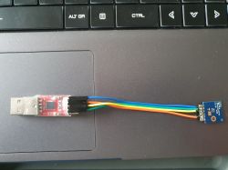
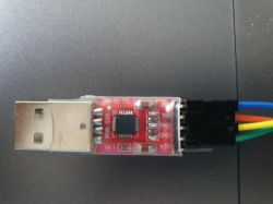
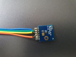
    USB to TTL adapter with wires connected to a module on a laptop keyboard. USB adapter with black, red, orange, yellow, green, and blue wires. Electronic circuit with attached wires in blue, green, yellow, and orange colors.

    Guess there's not much left other than trying to see if the cb2s still functions as part of the socket. Or, do yet another attempt at desoldering using another socket.
  • #25 21147683
    divadiow
    Level 34  
    it looks like your RX on module goes to RX on USB-TTL. It needs to be RX->TX, TX->RX, swap them at usb end.
  • #26 21147726
    p.kaczmarek2
    Moderator Smart Home
    What kind of LDO is used on this device? I don't think it can provide enough current. How do you reboot device? By disconnecting VDD?
    Helpful post? Buy me a coffee.
  • #27 21147776
    tun0
    Level 6  
    divadiow wrote:
    it looks like your RX on module goes to RX on USB-TTL. It needs to be RX->TX, TX->RX, swap them at usb end.


    I tried with both RX-TX/TX-RX and RX-TX/TX-RX. Do see a slight difference in behavior of the LEDs, but not really obvious enough to tell which one's correct. One of the earlier posts did mention RX-TX/TX-RX though.

    p.kaczmarek2 wrote:
    What kind of LDO is used on this device? I don't think it can provide enough current. How do you reboot device? By disconnecting VDD?


    Good question, no idea really. Do you have a recommendation for a suitable USB to UART device?
    And yes, disconnecting VDD.
  • #28 21147801
    p.kaczmarek2
    Moderator Smart Home
    Ok first, can you show us the second side of your USB to UART covnverter? Is there any LDO at all?
    Helpful post? Buy me a coffee.
  • #29 21148187
    tun0
    Level 6  
    p.kaczmarek2 wrote:
    Ok first, can you show us the second side of your USB to UART covnverter? Is there any LDO at all?


    The one I tried yesterday (red) appears to be very simple with nothing on the bottom. The one I tried before (blue) is quite a bit more complex:

    Two USB adapters on a white background. The top adapter is red, the bottom one is blue. Two USB-TTL converter modules, one red and one blue, on a white background.
  • #30 21148728
    p.kaczmarek2
    Moderator Smart Home
    None of those look promising. Still, what are those 3 soic chips at the bottom of the blue one?
    Helpful post? Buy me a coffee.

Topic summary

The discussion revolves around the BK7231N/CB2S/BL0937-based WiFi smart plug (RMC021) purchased cheaply from a Chinese online store. The user successfully disassembled the device, desoldered the CB2S module, and flashed it with version 1.17.493 using Easy UART Flasher. Participants shared insights on flashing procedures, including the importance of correct RX/TX connections and the use of specific tools like BK7231Flasher. Several users contributed templates and configurations for integrating the device with home automation systems, including Tasmota and ESPHome. Issues such as relay damage and difficulties in flashing were also discussed, with suggestions for troubleshooting and alternative methods for energy measurement using the BL0937 chip.
Summary generated by the language model.
ADVERTISEMENT