logo elektroda
logo elektroda
X
logo elektroda
ADVERTISEMENT
Treść została przetłumaczona polish » english Zobacz oryginalną wersję tematu
  • Hi,

    I have finally decided to share the design of a home automation system that I have implemented at my home and has been running successfully for several years. To begin with, I would like to describe the assumptions and general outline of the whole thing and in the following parts I will focus on specific parts.

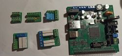
    Several small and one large PCB modules for a home automation system arranged on a white background. .
    Home automation modules and a main controller board with STM32 microcontroller and Ethernet ports. .

    Design assumptions
    The project is not new, the first elements started to be created about 10 years ago, and the whole thing has evolved since then but the main assumptions and communication protocol have remained unchanged. The aim of the project was to create a low-cost yet easily expandable home automation system from scratch, originally for lighting, with the possibility of expanding as required. Because of the price, I decided on a distributed topology with wired communication, i.e. one main control module and simple actuators connected to it by a control cable, placed where they are needed, e.g. directly at buttons and receivers. As a result, the routing of power cables was simplified - only the control cable is led to the light switches and the relays are placed in boxes on the ceiling directly next to the lamps. The second consideration was flexibility, i.e. the possibility of moving and attaching new modules. To this end, I decided to use a protocol allowing for multiple modules connected to a common bus. The system had to be as cheap as possible, so I decided to use one of the cheapest uCs I was already familiar with at the time, the Attiny family, in the modules. As I didn't expect to need to achieve any crazy transfer rates - after all, what does it take to switch on a light or send data from some sensor - I decided to experiment with a simple 4x0.5mm intercom cable, where 2 wires will be used to power the modules and 2 will be used for communication.

    Communication protocol basics
    With these assumptions, I decided to use the USI peripheral chip implemented in Attiny and implement CLK + DATA synchronous serial communication, a bit like I2C with changes to allow the transfer to be initiated by each module, with simultaneous collision detection.
    The CLK signal is given by the master module and it also transmits the frame start signal, so it is basically a slotted bus network. The low clock frequency (about 5kHz in the current version) makes the signal propagation time on the bus negligible, which also made it easier to implement collision detection. This is implemented in such a way that each module has a unique 8-bit address on the bus and this is transmitted as the first byte of the frame. In combination with the fact that each transmission is started by the control module, we obtain an address competition and in the event of a collision - i.e. more than one module starts transmission at the same time, all but one module that wins will notice the collision and cease transmission. Of course, this causes some modules to have priority over others, but with the number of frames being transmitted, this does not matter much. The master module always has its address at 0x00, which means it always has the highest priority in transmission. The simplicity of the algorithm has made it possible to fit the programme into modules of less than 2kB while maintaining high transfer reliability. the number of theoretically supported modules on the bus is 254 (addresses 0x00 and 0xFF are not allowed) but this can be increased by using several buses, the current implementation of the control module supports 8 buses. Each module has a unique permanently programmed 32-bit address, the 8-bit address is not permanently assigned to the modules - it is assigned by the master module during initialisation. The purpose of this solution is to shorten the transmitted frames.

    I/O modules:
    To date, several types of executive modules have been developed, the basic ones being input modules - 3 channel and 6 channel - and output modules - with 2 and with 4 relays. In addition to these, single modules have been developed that support 8 outputs and combine input and output functions. Another module is a module for humidity and temperature measurement, it supports the DHT11 and DHT22 sensors. There is also a module for atmospheric pressure sensor and a module with 3 PWM outputs for controlling RGB led lines. More modules are planned, for example for measuring electricity consumption. Despite the small flash memory, I managed to pack in the most important functions in the programme, such as error checking, retransmissions or protection against duplicate frames. The programme has been running for the last 10 years without any changes, mainly because any changes would require the extraction and reprogramming of all the dozens of modules buried in the boxes; so far I have not found a bug requiring such a service action. Below I give a schematic diagram of the pushbutton module, the number of components is minimal which translates into the price and size of the module.
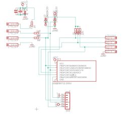
    Schematic diagram of a button module based on the Attiny13 microcontroller. .

    Control module:
    This element of the system has the most eventful history over the years various versions were created in succession and of course each time it was to be the final version, well that I like to experiment and improve so changes were inevitable. The first versions were realised using an Atmega32 uC, which worked but was quite simple and slow, then I moved to ARM chips, which made the whole thing work smoothly, and most importantly, the possibility of communication via ethernet appeared, which made it possible to realise a simple http server and support for an SD memory card.
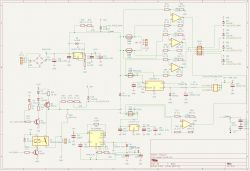
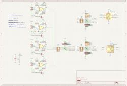
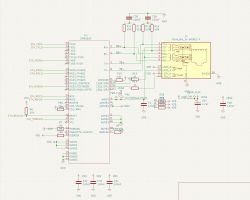
    The main module in the current version is based on the STM32H725 chip. It supports 8 buses. An ethernet input supporting http, telnet and ftp protocols is used to configure and communicate with the module - operation is possible from a web browser and via a telnet terminal. An SD memory card is used to store data collected from the sensors and html files, the basic system configuration is stored in the uC's flash memory for greater reliability. The power supply part of the module, in addition to the inverter that provides power to the entire network, also contains circuits for measuring voltages and currents at important points in the module and a module that supports a gel battery to power the system in the event of a mains power failure. The software is based on the FreeRTOS real-time system and uses the HAL library, the rest of the code is already written by me from scratch. Below is a schematic diagram of the main module.
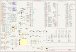
    Block diagram of a home automation main module with STM32H725, connectors, passive components, Ethernet controller, and SD card reader. .
    Schematic diagram of power supply and measurement circuit for a home automation main module. .
    Block diagram of an input/output module for a home automation system, showing connections between ICs, connectors, resistors, and capacitors. .
    Circuit diagram of the main module’s Ethernet section with DM9161A chip and RJ45 connector for a home automation system. .

    Next time I will describe in more detail what the communication protocol looks like, what frames are transmitted.

    If someone is not afraid of messing around and would like to see the soft for the executive modules and for the main module, it can be found on github. There is also a project of the main module board there in KiCad format
    https://github.com/r-gal/LON_devices/
    https://github.com/r-gal/LON_v2/
    https://github.com/r-gal/CommonLibs_v2/

    Cool? Ranking DIY
    About Author
    nuclear
    Level 16  
    Offline 
    nuclear wrote 188 posts with rating 127, helped 18 times. Live in city Siepraw. Been with us since 2003 year.
  • ADVERTISEMENT
  • #2 21531077
    gulson
    System Administrator
    Thanks for sharing the project, it's nice that you call it real and don't succumb to fashion - home automation, not marketing smart home.
    I will tell you that creating a home automation that will work faultlessly for many years is an art, many a manufacturer has failed, either with modules, or with the control panel, or most with subsequent software updates ;) Congratulations.
    Email me Parcelmate on PW and I'll send a small gift.
  • ADVERTISEMENT
  • #3 21531090
    TechEkspert
    Editor
    Interesting, everyone has practically thought about it but few have realised :) .
    Idea, design, realisation, corrections, trouble-free operation, these are the next rungs and each one is an order of magnitude more difficult than the previous one.

    If you would like to record an episode of the podcast https://www.elektroda.pl/rtvforum/audio.php together
    on this topic then feel free to email me on PW.
  • ADVERTISEMENT
  • #4 21531183
    nuclear
    Level 16  
    Thanks for the good word, I think several factors contribute to the stability of the system's operation, above all the simplicity of the protocol and the use of wired communication. I will now briefly describe what the data frames look like and how this translates into functionality.
    As I wrote, the bus is 2 wire,CLK + DATA. The lines are controlled similarly to I2C using the OC output and pulled up with a resistor to the supply voltage. The frame start and end signal is implemented in the same way - by changing the state of the DATA line when the CLK line is high. These events, as well as collision detection, are handled by the USI hardware chip in the Attina uC.
    List of currently implemented frames:

    Code: Text
    Log in, to see the code
    .

    The first byte of each frame is always the short sender address - in the case of the main module, this is 0. The next byte contains two pieces of information - the 4-bit frame code and the 4-bit frame size. The following bytes already depend on the type of frame. The direct response of the recipient to the frame is indicated in square brackets. The conrtol sum is very simple - it is the 8 or 4 bit XOR result of all the bytes in the frame.

    When the system starts up, all modules are uninitialised and have no short address assigned. To ensure configuration consistency, the main module still sends a DETACH_ALL frame - this is information for all modules to reset themselves. The main module then sends an ADRCONQUEST frame. In response, all uninitialised modules send their long 32bit address. Collision detection causes only one address to be sent in the end. The module with this address is configured using the DEVCONFIG frame, receives its short address and ignores further ADRCONQUEST frames, which are repeated until all modules have been initialised. The ADRCONQUEST frame will then be sent cyclically to detect modules connected during system operation. The master module also sends a CHECKDEVICE frame cyclically to all known modules to check their status.

    The remaining frames are already used for normal operation. The DATA_SW frame is sent by the module handling the inputs when an event occurs at an input. Up to 8 "Event" fields can be sent in one frame, This byte contains information about the port number (0-7) and the type of event (UP,DOWN for a port in bistable mode and PRESS,RELEASE,CLICK,HOLD for a port in monostable mode). The DATA_TR frame in turn is used to set the output on the module to a specific state. READ_IO allows the currently set state of the output to be read. The REQUEST frame is used in sensor modules to initialise a measurement, once the measurement is complete the module sends a DATA frame.

    The READ_STATUS frame is currently unused.

    In general each module can have up to 8 ports where each port can have a different function, this is permanently stored for the module. The module type is contained in the oldest byte of the long address. The basic modules are the SW3 module on an attiny25 which supports 3 inputs, the SW6 module on an attiny24 which supports 6 inputs, the RL2 module on an attiny25 and the RL4 module on an attiny24 - which support 2 and 4 outputs. There were also "unique" modules for a specific application, the RL8 with 8 outputs and the SPEC having 3 inputs and 5 outputs.
    Another module is the HIGRO module, which supports 2 ports to which sensors DHT11, DHT21 or DHT22 can be connected - one directly on the board and one additionally on a screw connector. The PRESS module supports the mpxhz6115a atmospheric pressure sensor. The PWM module is more complex, it has 3 PWM outputs to control the LED strips, 1 normal output (can be used, for example, to switch off the power supply for the LEDs) and 2 inputs. This is the only module whose programme does not fit into 2 kB, so it uses an attiny44 chip.

    The program for handling inputs is quite complex - it handles both bistable and monostable buttons, generating appropriate events. For monostable mode, there are 4 types of events - PRESS and RELEASE when the button is pressed and released, and CLICK - if the button is pressed quickly several times. If the button is pressed longer it will start sending a HOLD event cyclically. The times for these events are configurable. Debouncing on the inputs is implemented by software.
  • #5 21531444
    Sentymentalny
    Level 14  
    What is the longest cable between the control module and the executive module?
  • #6 21532172
    nuclear
    Level 16  
    >>21531444 .
    Currently, the distance from the control panel to the furthest module is about 20 metres, but taking into account the branches, the total cable length on the most extended bus is about 50 metres. However, I carried out tests using a spool of 100m cable. The distance itself did not turn out to be a problem, at the current clock frequency of 5kHz it is negligible when counting latency, and I did not notice any problems with external interference despite the fact that a large part of the cable is run together with the network cables. The most serious problem I had to deal with was the capacitance of the cable itself. A typical 4x0.5 ytdy cable has a capacitance of 100nF/km. It turned out that with longer cable lengths, crosstalk appeared between the CLK and DATA lines, which strongly disrupted transmission. I solved this quite simply - I further increased the capacitance between ground and the CLK and DATA lines - 10nF capacitors are added to these lines for this purpose. This of course increased the falling and especially the rising times of the signal, but still at this frequency it has no negative effect on the transmission and allowed to reduce the crosstalk to a satisfactory level.
  • #7 21532240
    Sentymentalny
    Level 14  
    Thank you very much for your extensive and detailed explanations.
    Congratulations on your determination and cool project.
    Is it possible to make available also an older version under atmega32?
    Perhaps following the design of the esteemed forum member, I will approach the implementation of a small actuator control from an electronic thermostatic head about 15 meters away.
  • #8 21532360
    nuclear
    Level 16  
    I will look for the sources for this version but, as far as I remember, it was not yet a sufficiently stable version and would need to take into account later patches.
  • #9 21532408
    Sentymentalny
    Level 14  
    Sure. Thank you in advance.
  • #10 21532497
    gulson
    System Administrator
    It would be cool to record a podcast with you, you can see you really know each other and the project is really interesting. All you need is a microphone.
  • #11 21533191
    nuclear
    Level 16  
    In this section, I will focus on the core module itself.

    The main functions of this module are:
    -Operating the actuator modules, i.e. detecting them, configuring them and cyclically checking their status.
    -Serving data from the executive modules, e.g. from buttons, and performing programmed actions, e.g. setting the appropriate output
    -Checking the current time in order to carry out scheduled events, e.g. timers, smooth switching on and off of LED lighting at a scheduled time, etc.
    -Cyclical download of sensor data, recording on SD memory card and possible operation of outputs, e.g. switching on a fan.
    -FTP server - allows reading and writing of files on the SD card, Currently the server supports up to 2 clients.
    -TELNET server - allows communication with the main module for reading the system status, monitoring resources and above all for managing the configuration of all modules. This server also supports up to 2 clients.
    -Http server - Enables selected data such as output status, current and historical data from sensors to be read out using a web browser. It is also possible to change the status of the outputs and configure the timers. The server supports up to 12 clients in the current implementation.
    -NTP protocol support - the chip synchronises the time with a time server.
    -The module has a built-in battery management circuit for power supply backup, with basic functions such as charging, voltage control and over-discharge protection.
    -Power supply circuit is adapted to be supplied from a typical 16V AC transformer for control panels, It has a built-in converter to obtain 5V on which the entire system operates. the 3.3V voltage for the uC is obtained using an LDO linear stabiliser.
    -Current and voltage monitoring to control operating parameters and energy consumption. The input voltage, on the battery and on the battery are measured, The currents consumed separately by the uC and the individual buses are measured.

    I chose the STM32H725 chip because, firstly, I like ARM chips from this manufacturer, secondly, it has everything I need, i.e. sufficient memory, both Flash and RAM, and a built-in Ethernet controller, and thirdly, because it was at a good price.
    One of the objectives was to implement remote software updates without any noticeable impact on system operation. To this end, I decided to divide the available memory so that I could have two versions of the software at the same time, where during the execution of one version, the other could be updated and then there would be a quick reboot and the new version would be launched, possibly automatically reverting to the previous version in case of problems.
    The STM32H725 chip has a total of 1MB of Flash memory divided into 8 sectors of 128kB each. In this project I have divided it in such a way that sector 0 contains the bootloader, sectors 1-2 contain the first version of the program, sectors 3-4 contain the second version of the program. The remaining 3 sectors are used to store the system configuration.
    The purpose of the bootloader is to copy the appropriate version of the software into the ITCM memory and then jump to that location in, i.e. run that version. The software could be run directly from Flash memory but this would require compiling the code already with the choice of which slot it would be loaded into, in the current implementation the code is compiled to run in the ITCM address space. Unfortunately, however, I will most likely have to forfeit running the program from Flash memory or optimise the memory usage more Flash because I am finding it difficult to allocate more than 192kB of ITCM memory and the programme is slowly reaching this size. I'm hoping that I still have a little left over to reach the next threshold of 256kB. The program is based on FreeRTOS and is divided into several processes which communicate with each other. If there is interest in the subject, I can describe the structure of the program in more detail.


    .
  • #12 21533691
    Sentymentalny
    Level 14  
    I am interested :-) .
  • #13 21534015
    Sam Sung
    Level 33  
    How much power does this system consume?
    How often is it useful to have the function of switching the lights on and off in the room while you are out? (It seems to me that most of the installation cost is consumed by this function).
    What is the programming of the thermostat / timer - can logical expressions be configured? (E.g. between 11am and 6pm, if it is at least 40 degrees on the solar collector and 10 degrees more than the tank, with a hysteresis of 2 degrees, turn on circulation pump 2).
    Do you have a 10 year history of lights on and off in each room and do you also archive this outside the SD card? :) Is the same SD card still running from the beginning?
    Is the system accessible via the internet?
  • ADVERTISEMENT
  • #14 21534258
    nuclear
    Level 16  
    Sam Sung wrote:
    How much power does this system consume?


    With the lights off about 5W measured after the power transformer, Each light on adds 120mW to this to power the relay. Modules with bistable relays could be considered, especially for outputs that are on for long periods.

    A screenshot fragment showing a table with current and voltage readings for various ports and components of an electronic system. .

    Sam Sung wrote:
    How often is it useful to have an on/off function for lights in a room while you are out? (It seems to me that most of the installation costs are taken up by this function.)


    As you can guess, this function is used occasionally - just for example while lying in bed I will remember that I did not switch off the light somewhere. For this function alone the system does not make much sense. In the case of lights, the system is useful for:
    -Timer switches for outdoor and night-time lighting
    -Easy implementation of staircase switches, e.g. in the corridor one lamp is controlled by 4 buttons, which also benefits aesthetics as the switches are always in the same position.
    -Control of several outputs with one switch.
    -Reconfigurable, e.g. with lights in the corridor or in the room by the bed.
    -Programmable timer lights - lights that switch off after a certain time, useful for example in some cells.

    Sam Sung wrote:
    How is the programming of the thermostat / timer - can logical expressions be configured? (E.g. between 11 a.m. and 6 p.m., if there is at least 40 degrees on the solar collector and 10 degrees more than in the tank, with a hysteresis of 2 degrees, switch on circulation pump 2.)
    .

    I have considered running some simple scripts which the user could enter and which would be triggered by various events, but for the time being it was not urgent enough to do so.

    Sam Sung wrote:
    Do you have a 10 year history of lights on and off in each room and do you also archive it off the SD card? Is the same SD card still running from the beginning?
    .

    I don't archive such events - I don't see the point in it. I'm only archiving sensor data, there were supposed to be system error logs but that's also waiting to be implemented, anyway it wouldn't be much. I have not yet added data collection in the event of an unintentional restart, but this is not critical either, I have not recorded any so far in this version. In practice, sensor data history is only used for weather data - temperature, humidity, pressure and precipitation. Off-card archiving is done occasionally "manually" for the time being. The card was prophylactically changed about two years ago. I once had a problem with a dead card in an earlier version, which was the impetus for moving the basic configuration from the memory card to flash memory (in the process I greatly reduced ram consumption). The card should last a long time because the data structure is that every day a new data file is created, so there is no situation that a sector is modified particularly often.

    Sam Sung wrote:
    Is the system accessible via the Internet?
    .

    Here, too, I would say that there was a lack of time - for the time being, access is only on the local network. Going "outside" would require adding encrypted connections. In addition, I lack knowledge and experience in the area of such connections , some hosting etc. Maybe one day I will add because it is something that would be useful sometimes, but for now - too many projects too few hands ;) .

    I am currently extending the functionality to support a system for watering the garden. So far I've used timers for this, this year I've finally added a rain gauge so I want to add the inclusion of air temperature and precipitation into the watering time calculation, maybe in the future I'll also add soil moisture sensors. I also plan to expand the weather station to include wind measurement.
  • #15 21534347
    DJ MHz
    Level 25  
    Tie it through some simple router with openwrt and the way to the world open with tunnels ;)
  • #16 21534969
    Sam Sung
    Level 33  
    nuclear wrote:
    Sam Sung wrote:
    How is the programming of the thermostat/timer controller - can you configure logical expressions? (E.g. between 11am and 6pm, if there is at least 40 degrees on the solar collector and 10 degrees more than the tank, with a hysteresis of 2 degrees, turn on circulation pump 2.)
    There is no such possibility yet because there has been no need for it - there is only a basic thermostat/hygrostat with hysteresis, i.e. exceeding a certain level on a given sensor can cause a change of state of the programmed output,
    And what happens when different settings switch the same output?

    nuclear wrote:
    Sam Sung wrote:
    Do you have a 10 year history of lights on and off in each room and do you archive it off the SD card as well? Is the same SD card still running from the beginning?
    I don't record such events - I don't see the point in it.
    I understand, although the history of w(y)-connected outputs can be useful for looking for anomalies in the operation of appliances, e.g. a fridge, heating or solar panel (e.g. as in the graphs in >>20941345 ).

    DJ MHz wrote:
    Tie it through some simple router with openwrt and the way to the world open with tunnels ;)
    Router would double the power consumption and force changes in architecture, e.g. why then a telnet, ftp, http server on the STM when a better one is on the router :) .
  • #17 21535066
    nuclear
    Level 16  
    Sam Sung wrote:
    And what happens when different settings switch the same output?
    .

    I didn't design it for such an application, but as I think about it, it should conditionally work. If the reading is inside the hysteresis, then there is no problem for another source to override the output. If, on the other hand, two sources try to set a conflicting condition, this will result in short pulses at the output with each measurement series. In fact, the same will happen if you set 2 timers for the same output.

    Sam Sung wrote:
    I understand, although the history of output w(y)-connections can be useful for looking for anomalies in the operation of appliances, e.g. a fridge, heating or solar panel (e.g. as in the graphs in >>20941345).


    It would be altogether simple to add something like this, with the option that you could set a flag for each port in the module as to whether it should be logged or not. I guess I need to start writing down ideas and looking for people willing to implement :P .

    Sam Sung wrote:
    Router would double the power consumption and force changes in architecture, e.g. why then a telnet, ftp, http server on the STM when a better one is on the router
    .

    I was experimenting with something similar, i.e. the previous version of the main module was on a simpler STM32F446 chip with no built-in Ethernet. A Raspberry Pi Zero with WiFi was connected to the module and they communicated with each other over SPI. However, I abandoned this idea due to annoying problems with the Raspberry, it could go silent after a few days and had to be manually restarted. The lack of telnet directly in the module also made it difficult to configure the module - everything had to be converted and pushed over SPI. Overall, my lack of experience with Raspbian and other Linuxes and wandering around in the dark put me off this solution a bit. So I'm definitely not in favour of taking the servers out of the module somewhere else, possibly part of the HTTP server - part of it has to stay on board anyway to handle e.g. commands from the browser to switch something. Maybe someday I will find the time to learn more about tunneling and so on - for now it's black magic to me, i.e. I know in general how it works, but how to get it working both on the server and client side I have no idea.
  • #18 21541259
    nuclear
    Level 16  
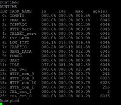
    I am adding the promised short description of the code structure in the main module. With this level of complexity, I decided to use a real-time system, I chose the already known FreeRTOS. This allowed me to divide the functionality into individual processes. Below I paste a printout with all the processes and another with the sockets.

    Terminal output showing a list of active FreeRTOS system processes and current network socket connections. .

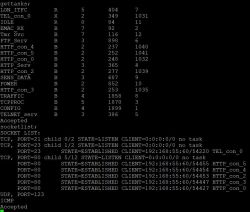
    The Tmr Svc and Idle processes are system processes. The CONFIG process is to configure and start all peripheral chips after a reboot and later check their status, such as the status of the memory card. The TRAFFIC process is the main process handling network events, i.e. button state changes, all timers, sensors. The LON_ITFC process handles directly the receiving and sending of frames on the buses, This is done purely software using only GPIO. The other processes are already optional. The SENS_DATA process has the task of storing sensor data on the memory card and also handles requests for data from the HTTP server. POWER, on the other hand, handles the monitoring of all voltages and currents as well as the battery status.
    Serving the Ethernet lines is the TCPPROC process, which handles all incoming packets; it also handles the ARP, DHCP, ICMP and NTP protocols directly. Auxiliary to it is the EMAC_RX process which pre-filters incoming packets and monitors the connection status. Further processes are the server processes (FTP_serv, HTTP_serv and TELNET_serv). When a TCP connection is established, a separate process is created for it which is deleted when the connection is terminated. Several such processes are visible on the printout, and can be associated with the listed sockets.

    The program is divided into 2 repositories - in one there is a part directly related to this project, in the other one, the common one, it contains libraries written by me to handle the TCP stack and the FAT file system.

    Processes communicate with each other in 3 ways. The first is semaphores, which are basically only used to share IO circuits, i.e. the SD card and the Ethernet TX interface.
    The second and most popular is data transmitted via queues, i.e. one process allocates a packet and puts it into the recipient's queue and the recipient pulls it out of the queue and handles it.
    The third one is basically a modification of the second one in that the first process, after passing the packet to the queue, suspends its execution and waits for a response. The recipient process sends a message to the sender indicating that it has finished processing the data o causes the sender to wake up and continue executing the programme.

    Interrupt handling also makes use of these mechanisms - most often an interrupt causes an information about the interrupt to be thrown into the process queue, which will result in its further handling.
  • #19 21554886
    nuclear
    Level 16  
    Hi,
    As there has been a request to be able to provide a simplified version for a different uC I will provide a short instruction on how to customise the project.
    Generally in the current version two processor families are supported i.e. STM32F4xx and STM32H7xx - probably shouldn't be much of a problem with other similar STM chips but I haven't tested this, I've run a similar slimmed down version in the past on an STM32F091 chip so with a little modification it should also work now.

    In this example I will show how to run the project on the STM32F446. This chip does not have an ethernet so all the functionality associated with it is not available. We will use a UART terminal to communicate with the module. I'm assuming that the person using this instruction already has basic experience in developing a project on STM32 chips, i.e. that they can create a project, compile and upload it to the uC. As far as the hardware part is concerned, you don't need much to experiment with - any evaluation board with our uC will do, you just need to add pulling up the bus lines with a 4.7k resistor to 5V and, of course, making sure you use an IO which can work with this voltage.

    From my github profile we download the LON repositories at least v1.1 and CommonLibs also at least v1.1. These will be needed in several steps.
    In the first step, you need to create a new project for the STM32F446. I use the Segger Embedded Studio environment for this, so for other environments some of the steps will probably need to be adapted. The program in this version will be executed directly from flash memory so there is no need to upload a bootloader.
    To start with, we need to check if the generated interrupt vector table is correct and complete, to do that we compare it with Cortex_M_Startup_STM32F446.s file from LonMain directory. It is important that the names of the interrupt handler functions are the same. You can help yourself here with the STM32CubeMX tool which I used, among other things, for this purpose. By generating the project in this tool, we also get the libraries for our chip (Drivers/CMSIS and Drivers/STM32F4xx_HAL_Driver).

    /* Attaching CMSIS and HAL files*/ .
    The next step is to include these libraries in the project, to do this we add the paths to the library directories in the project settings - User Include Directories:


    add definitions in the project settings - Preprocessor Definitions:
    STM32F446xx

    We attach the files to the code:
    system_stm32f4xx.c
    hal.c
    hal_cortex.c
    hal_gpio.c
    hal_tim.c
    hal_tim_ex.c
    hal_iwdg.c
    hal_rcc.c
    hal_flash.c
    hal_dma.c
    hal_uart.c

    We create the file stm32f4xx_hal_conf.h based on stm32f4xx_hal_conf_template.h and in it we set USE_HAL_TIM_REGISTER_CALLBACKS to 1

    /* Include FreeRTOS files */ .

    In the next step we will take care of attaching the files for FreeRTOS. For this, we download the latest version from the official site and unzip it. The files we are interested in can be found in the FreeRTOS-Kernel directory.

    Add paths to directories with libraries in the project settings - User Include Directories:
    FreeRTOS-Kernelinclude.
    You should also add the appropriate version of the libraries for your platform and compiler, in my case it is
    FreeRTOS-Kernel_portable_ARM_CM4F.

    Attach the files to the code:
    croutine.c
    event_groups.c
    list.c
    queue.c
    stream_buffer.c
    tasks.c
    timers.c
    and from the appropriate portable directory:
    port.c

    Copy the FreeRTOSConfig.h file from the LON/LonMain repo
    The value of configTOTAL_HEAP_SIZE is set to use the available memory in the STM32F446, if using a different chip this needs to be changed.

    /* Include application files */ .

    Once we have all the libraries in place we'll get on with attaching the actual code. To start with, if it was generated then we remove the main.c file.


    Add paths to directories with libraries in the project settings - User Include Directories:

    \`MyLibs.
    \MyLibsLON.

    Include files from the LON/LonMain repo
    CommandSystem.cpp/hpp
    CtrlProcess.cpp/hpp
    main.cpp/hpp
    SystemInit.cpp/hpp
    CommandConfig.hpp
    CommonDef.hpp
    LonConfig.hpp
    SignalList.hpp

    include files from the CommonLibs/MyLibs repo

    commandHandler.cpp/hpp
    commonSignal.cpp/hpp
    HeapManager.cpp/hpp
    UartTerminal.cpp/hpp
    UartTerminalPhy.cpp/hpp

    include files from the LON/MyLibsLON repo

    LonChannel.cpp/hpp
    LonChannelBasic.cpp/hpp
    LonCommands.cpp/hpp
    lonDatabase.cpp/hpp
    LonDevice.cpp/hpp
    LonInterfacePhy.cpp/hpp
    LonInterfaceProcess.cpp/hpp
    LonSensors.cpp/hpp
    LonTrafficProcess.cpp/hpp

    /* configuration */ .

    In the LonConfig.hpp file we set:
    - How many buses we want to use: NO_OF_BASIC_CHANNELS value from 1 to 8.
    - Which flash memory space will be used to store the configuration, we need at least 3 sectors

    In the CommonDef.hpp file we set:
    - The correct GPIO values for the buses - DATA_x_Pin,DATA_x_Port, CLK_x_Pin,CLK_x_Port

    In the file SystemInit.cpp:
    - in the SystemClock_Config function set the expected uC clock configuration, in the example for the STM32F446 the clock uses HSI and PLL getting 30MHz and an external LSE resonator for the RTC.

    The uart connection settings can be changed in the UartTerminalPhy.cpp file - the default is bitrate 38400, 8 bit, no parity, 1 bit stop.

    In this form, the project should compile and run. It is the simplest possible version and, once compiled, takes up about 66kB of Flash memory. You can run some more useful functionality at this stage:

    /*** RTC clock: ***/ .

    set the CONF_USE_TIME 1 flag in CommonDef.hpp

    include files from the CommonLibs/MyLibs repo:
    TimeClass.cpp
    TimeClass.hpp

    We include the files in the code:
    hal_rtc.c
    hal_rtc_ex.c
    hal_exti.c
    hal_pwr.c
    hal_rcc_ex.c

    /*** timers ***/ .

    requires RTC
    RNG is recommended when using RGB timers - unfortunately the STM32F446 does not have it so a very primitive trick is done in the form of using the SYSTICK counter value as a pseudo-random value. For this application it should be sufficient.

    set the USE_TIMERS flag 1 in LonConfig.hpp

    include files from the LON/MyLibsLON repo:
    LonTimers.cpp
    LonTimers.hpp

    /*** Sensors ***/ .

    requires RTC

    set USE_SENSORS flag 1 in LonConfig.hpp

    include files from the LON/MyLibsLON repo:
    LonSensors.cpp
    LonSensors.hpp

    After adding these modules, the program is about 83kB after compilation

    I will try to add a short description of the commands to the terminal in the near future.
  • #20 21570772
    nuclear
    Level 16  
    Hi,

    I've finally put together a short description of the most important commands, I haven't yet described here the commands for networking, sockets etc, I'll do that as I'll be describing how to include these modules in the compilation, if anyone is still interested ;) .
    Commands are structured as komenda@arg1=arg1val,arg2=arg2val,...,argN=argNval; If an argument is in square brackets in the description it means it is optional.

    Basic system commands:

    sysinfo; - shows system status, version time of last reboot, etc.

    gettime; - displays the system time.

    settime@[YEAR=2005],[MONTH=4],[DAY=6],[WDAY=4],[HOUR=14],[MIN=5],[SEC=6]; - sets the system time.

    Device-related commands:

    getdevlist@[CHNO=0]; .
    Displays all devices connected to the buses, specifying the CHNO argument with the bus number only displays devices on that bus.

    configdevice@LADR=ladr,[PCNT=pcnt],[WCNT=wcnt],[PORT=port,[NAME=name],[ENA=ena],[INV=inv],[BIS=bis],[MODE=mode],[RLADR1=ladr],[RPORT1=port],[RLADR2=ladr],[RPORT2=port],[TMOCNT=tmocnt] ]; .
    This is probably the most important and extensive command, it is used to configure devices.
    LADR - the address of the device you are configuring, you specify it in hex format e.g. 0x1000000.
    PCNT means the time below which a button click will be treated as "fast". This is not currently used.
    WCNT means the time after which, when the button is pressed, the module will start cyclically sending a "HOLD" event indicating that the button is still pressed, this is used in some operating modes to change the sequence of lights, it can also be used to implement a dimmer - so far not running as I don't have dimmers at home ;) .
    The other parameters relate to the specific input/output of the module so require the PORT parameter (0..7).
    NAME - the name of the input or output, i.e. any string of up to 12 characters.
    The ENA, INV and BIS parameters take the values 0 or 1.
    BIS indicates what type of input it is, 0 means a monostable button, 1 means a normal bistable switch.
    INV is used to indicate whether the button is NO or NC for a monostable button. For a bistable button it is used to negate the state.
    MODE indicates the mode in which the port will operate, possible values are:
    STD - basic mode of operation, turns on and off the set outputs (1 or 2) when the button is pressed.
    2RL - same as STD only that it also supports the HOLD event which changes the sequence of the 2 outputs 11->01->10->11 being switched on. A simple click switches it off and on.
    TMOCNT - the same as STD except that it automatically switches off after a time specified by the TMOCNT parameter. The time is given in deciseconds, i.e. TMOCNT=10 means that the output will switch off after 1 second.
    AUTO - the operating mode used only by the rain sensor for the time being, as it uses a normal input module. The input impulses are redirected to the corresponding procedure
    DHT11 and DHT22 - these two modes apply only to temperature and humidity sensor modules, it is used to define what type of sensor is connected to the module.

    RLADR1,RLADR2,RPORT1,RPORT2 - output module address and port number in this module.

    printdevice@LADR=ladr ; - Displays the configuration and status of the respective module.

    replacedevice@OLDLADR=ladr,NEWLADR=ladr; - Useful when replacing e.g. a defective module, searches the configuration and replaces the address.

    setoutput@LARD=ladr,PORT=port,VAL=val; - changes the output state in the relay module, val takes values (0..1)

    setpwm@LARD=ladr,PORT=port,VAL=val; - changes output state in pwm module, val takes values (0..255)

    rainsensor; - If we use rain sensor this printout shows us statistics from last 48 hours ( older ones are available if we use SD memory card)

    Commands for timers:

    printtimers; - displays all timers.

    settimer@IDX=idx,[NAME=name],[ENA=ena],[T0=time]...[T5=time],[LADR1=ladr],[PORT1=port],...[LADR3=ladr],[PORT3=port],[TYPE=type],[SEQ1=seq],[SEQ2=seq]; .

    IDX - timer setting number (0..11)
    NAME - name,max 12 characters
    T0..T5 - time in HH:MM format.
    OUT1..OUT4 - output module address
    PORT1-PORT4 - port of the output module
    TYPE- (0,1), 0 is a normal timer, 1 cooperates with the PWM module and realises smooth switching on and off, it controls simultaneously 3 outputs in the module generating random colour sequences while switching on. This mode of operation was created to realise lighting in the bedroom - it turns on before the alarm clock.
    SEQ1, SEQ2 - to configure the PWM mode , SEQ1 is associated with the time interval T0-T1, SEQ2 is associated with the time interval T2-T3. Currently 2 versions are implemented. 0- normal, 1 - with reduced blue content.

    The timer is enabled if the current time is between T0 and T1 or between T2 and T3 or between T4 and T5 - assuming T1 > T0, T3 > T2 and T5 > T4. For example, if you want the timer to switch on between 7:00 and 8:00 then set T0=07:00, T1=08:00, T2..T5 = 00:00, while if you want the output to be active between 23:00 and 1:00 then set T0=00:00,T1=01:00,T2=23:00,T3=24:00, T4..T5=00:00.

    Other commands:

    printdatabase; - displays memory usage for configuration

    defragconfig; - retrieves 'used' memory blocks.

    formatconfig; -removes the entire configuration of the modules.Should be performed after the first boot, before starting to configure the system.

    formattimers; - deletes the entire configuration of the timers .Should be executed after the first startup, before starting to configure the timers.

    Other system commands:

    getmeminfo; - displays memory usage statistics

    gettasks; - displays a list of processes
  • #21 21590455
    nuclear
    Level 16  
    I have reorganised the code to make it simpler to run, separated the custom code from the code generated by STM32CubMX so there is no doubt who is the author of what. I have also added the STM32CubMX project itself and new instructions, there are two depending on whether you rely on the FreeRTOS included by STM32CubeMX or the one included on its own. The main disadvantage of the included automatically is the version - 10.3.1 - in which it is not yet possible to define separately the address space for process stacks and this is quite a useful feature.
    I have abandoned - at least for now - the BOOT module. Currently, the programme is executed directly from flash memory due to the increasing size of the code. Eventually, the programme will be updated directly in flash memory by a bootloader loaded in ram memory or in another flash sector.
    There is new functionality - a module to control the irrigation of the garden which uses data from the temperature sensor and rain sensor to calculate the irrigation time.
    In addition, I have started a module to measure CPU load by process. When executing the programme from flash it is quite good:

    Bar chart showing percent CPU usage by different processes in an embedded system. .

    In the next stages I plan to add dimmer support and add event logging.
ADVERTISEMENT