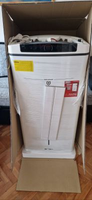
I've bought some cheap BNETA B22 RGBCCW bulbs locally and wanted to try flashing them with OpenBeken. I wanted to first try tuya-cloudcutter, but didn't know if these contained Beken or ESP chips (old or new stock etc.), so linked them to Smart Life to see firmware version. I stupidly did an update to firmware 1.0.0(1.6.0) (MCU on 1.6.0), which I think fixed the exploit, so couldn't connect to them via cloudcutter.
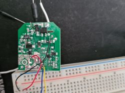
Alas, I tore into it and found a BK7231N chip directly soldered to the board. I've been trying to flash via UART for several hours, but cannot get the chip into bootloader. I checked that the chip is receiving the serial data with oscilloscope and it is, but I'm getting nothing on the RX, no matter how many times I turned power off/on or pulled CEN low with various timings. RX is kept high (as it should), but no data at all, beyond the initial hiccup after CEN that enables it.
Tried:
- Shorter wires, keeping wires apart etc. Also checked the waveform on oscilloscope to ensure it's clean and it looks fine?
- Checked continuity on all soldered connections
- No breadboard direct connections and otherwise
- Tried swapping TX/RX (oscilloscope shows which way is correct as you cannot drive the signal into a driven high port)
- Different USB ports (in case the TX signal somehow was insufficient)
- Different serial TTL adapters (currently using CH340G, but even tried with homebrew ESP32 passthrough to no avail)
- Checked all the other pads as there are two others connected (presumably) to the PWM pins that chat via I2C to the LED controller on the other board.
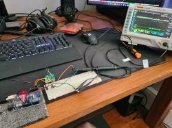
Setup:
- USB to Geekcreit Arduino Uno board (3.3V version) with CH340G
- Atmel held in reset to bypass and using TX/RX to BK7231N via thin 30AWG wire.
- 3.3V LDO powering both with sufficient power
- Using Easy UART GUI flasher
- Oscilloscope connected to TX/RX for debug
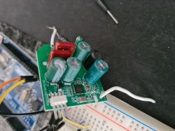
Is there any knowledge about perhaps the bootloader being overwritten with the latest firmware, effectively disabling the UART? I don't have access to the SPI pins unfortunately as it's not a module, so cannot flash it that way. Not unless I get really good at soldering leads on QFN.
Any other help will also be appreciated!
AI: Could you provide a detailed wiring diagram or at least specify exactly which pins on the BK7231N you connected to TX, RX, GND, CEN, and any other relevant lines during your UART flashing attempts?
BK7231N has pads for U1_TX/U1_RX which is connected to RX/TX on serial board. GND is shared and connected to GND pad on board. There is a 3.3V pad on the board that is connected to LDO, that I checked has 3.3V. I use a loose wire connected to GND to pull CEN low.
AI: Did you try manipulating any BOOT or GPIO pins (in addition to CEN) to force the chip into bootloader mode, or was your approach solely based on toggling CEN? If so, which pins and what sequence did you use?
I tried other GPIO pins, but only CEN did anything noticeable. The two other GPIO pins are likely connected to PWM on pin 24 and 26 (as is traditional), and the other one is labelled P21. I can't get anything off of this pin.
Added after 18 [minutes]:
Literally just as I posted this I saw the voltage levels of TTL was 4V, which is too high for the BK chip. Put it through a voltage divider to get it closer to 3.3V and it worked...
Alas, I tore into it and found a BK7231N chip directly soldered to the board. I've been trying to flash via UART for several hours, but cannot get the chip into bootloader. I checked that the chip is receiving the serial data with oscilloscope and it is, but I'm getting nothing on the RX, no matter how many times I turned power off/on or pulled CEN low with various timings. RX is kept high (as it should), but no data at all, beyond the initial hiccup after CEN that enables it.
Tried:
- Shorter wires, keeping wires apart etc. Also checked the waveform on oscilloscope to ensure it's clean and it looks fine?
- Checked continuity on all soldered connections
- No breadboard direct connections and otherwise
- Tried swapping TX/RX (oscilloscope shows which way is correct as you cannot drive the signal into a driven high port)
- Different USB ports (in case the TX signal somehow was insufficient)
- Different serial TTL adapters (currently using CH340G, but even tried with homebrew ESP32 passthrough to no avail)
- Checked all the other pads as there are two others connected (presumably) to the PWM pins that chat via I2C to the LED controller on the other board.
Setup:
- USB to Geekcreit Arduino Uno board (3.3V version) with CH340G
- Atmel held in reset to bypass and using TX/RX to BK7231N via thin 30AWG wire.
- 3.3V LDO powering both with sufficient power
- Using Easy UART GUI flasher
- Oscilloscope connected to TX/RX for debug


Is there any knowledge about perhaps the bootloader being overwritten with the latest firmware, effectively disabling the UART? I don't have access to the SPI pins unfortunately as it's not a module, so cannot flash it that way. Not unless I get really good at soldering leads on QFN.
Any other help will also be appreciated!
AI: Could you provide a detailed wiring diagram or at least specify exactly which pins on the BK7231N you connected to TX, RX, GND, CEN, and any other relevant lines during your UART flashing attempts?
BK7231N has pads for U1_TX/U1_RX which is connected to RX/TX on serial board. GND is shared and connected to GND pad on board. There is a 3.3V pad on the board that is connected to LDO, that I checked has 3.3V. I use a loose wire connected to GND to pull CEN low.
AI: Did you try manipulating any BOOT or GPIO pins (in addition to CEN) to force the chip into bootloader mode, or was your approach solely based on toggling CEN? If so, which pins and what sequence did you use?
I tried other GPIO pins, but only CEN did anything noticeable. The two other GPIO pins are likely connected to PWM on pin 24 and 26 (as is traditional), and the other one is labelled P21. I can't get anything off of this pin.
Added after 18 [minutes]:
Literally just as I posted this I saw the voltage levels of TTL was 4V, which is too high for the BK chip. Put it through a voltage divider to get it closer to 3.3V and it worked...


