logo elektroda
logo elektroda
X
logo elektroda

Assistance in selecting a control unit for a double-leaf gate

rafal222u 213 14
ADVERTISEMENT
Treść została przetłumaczona polish » english Zobacz oryginalną wersję tematu
  • #1 21560393
    rafal222u
    Level 4  
    Hello forum,

    I would like to install a bi-fold gate, controlled automatically. Due to the fact that the gate will be installed on a rather large side slope, I cannot install a normal straight gate.
    It seems to me that the best solution would be to build the gate to size, where the leaf that is higher up, in order to open inwards, will have to have its lower part lifted upwards to allow it to open on the slope inwards. I hope you understand what I mean? :) .
    So I would need a controller to control the opening of the left and right sashes and the lower part of one sash that would open upwards.
    Do you have any ideas on how to achieve this functionality?

    I would be grateful for any hints
    AI: What are the approximate dimensions and weight of the gate leaves and this lifting lower part? This will help in selecting the appropriate actuator and controller. .
    The full width of the gate will be about 4-5m, so each leaf half that size. As for the weight of the wings, I haven't chosen the gate itself yet, so it's hard for me to say specifically here.
    AI: How would you like to control the gate - do you care about a remote control, an app, or perhaps integration with a smart home system? Do you have any additional requirements for the functionality of the controller? .
    I would like a remote control, an app and preferably the ability to control relay open/close from an external smart home system.
  • ADVERTISEMENT
  • #2 21560632
    Plumpi
    Heating systems specialist
    The simplest solution is a sliding gate. You can find quite a few videos on YT on how such a gate should be made and installed.
    The trick is that the track of such a gate must be installed parallel to the plane of the slope.

    Another method is the bifold gate, but such a solution is for relatively small slopes.

    The leaf can then go up slightly when tilted. This can be achieved in 2 ways:
    1. the leaf would go up slightly on long hinges during opening. It would be lifted by a roller mounted under the sash, close to the hinges, riding on a suitably formed raceway. A treadmill in the form of a steel section (quarter) of a wheel, mounted with exactly the right plane of inclination, so that the end of the gate leaf would be raised above the ground plane.
    (2) The same can be achieved by mounting the leaf on hinges with the correct offset. The lower hinge would not be mounted exactly in the plane of the leaf, but offset slightly to the side on the cantilever in the same direction as the leaf would open. This mounting of the hinges would cause the end of the gate leaf to lift gently during opening. The leaf, when opened, would also be gently inclined and would not be vertical.
    In this case, the hinges would have to be ball hinges (ball joints). Although it is also possible to use ordinary ones, but they would have to be welded on at a slant.
    Normal swing gate actuators can be used, but make sure that the mountings of this actuator are mounted exactly in the opening plane of the gate, and this should be parallel to the ground plane. That is, we do not look at the vertical and horizontal, but stick to this inclined plane.

    Of course, there can also be a split leaf and the lower part tilted or lifted up.
    The uplift can be realised in a similar way to the uplifted wing, i.e. by means of a roller moving on a treadmill.
    It can also be realised by means of outriggers with joints.
    But here you have to size the planes quite well and calculate the lengths of the outriggers and joints that lift this part of the wing upwards. There is a bit of fun involved.
  • ADVERTISEMENT
  • #3 21560659
    rafal222u
    Level 4  
    Thank you for your quick response.

    A sliding gate would look best, but due to the terrain and green objects (tree), I have no way to physically install this.

    I have seen on YT such gates that float upwards when opening, but somehow I don't like this solution visually.

    It seems to me that this lifting of the lower part of one of the halves would be the best solution. Is it possible to implement the lifting of this lower part of the leaf with an additional actuator instead of a pull rod?
  • #4 21560702
    Plumpi
    Heating systems specialist
    rafal222u wrote:
    I've seen on YT such gates that float upwards when opened, but somehow I don't like this solution visually.


    I don't know if you understand what I mean.
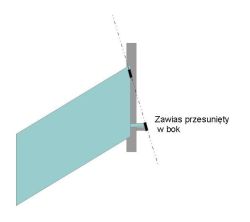
    So I'm posting this simple drawing of what it would look like:

    Schematic drawing of a gate with a hinge shifted sideways on an extension arm. .

    The lower hinge would have to be offset slightly to the side on the outriggers.

    The angle of the axis of rotation of the hinges, relative to the vertical, would have to correspond to the angle between the ground plane of the gate and the bottom line of the leaf.
    With the gate closed, the plane of the leaf would coincide with the plane of the post.
    The leaf must be trapezoidal in shape and must slope slightly downwards at the end so that the bottom of the leaf is parallel to the terrain. As the sash opens, the end would maintain a constant distance from the ground plane throughout the movement.
    This is the simplest and least cumbersome solution. It is also aesthetically pleasing. After closing the gate, you cannot see that the wings are different (one whole and the other divided), that there are any additional cylinders on the wing.
    Of course, lifting the lower part with an actuator is not that complicated. It is practically possible to use the additional control output of the control unit to actuate this third actuator.

    Of course, you can also make the wing part lift with an actuator, but you have an additional cost and more complications, and damage can occur if this third actuator fails or gets blocked.
  • #5 21560711
    rafal222u
    Level 4  
    I understand this solution with angled hinges, but it seems quite a bit of geometry to make it all look good and work without undue stress.

    It seems to me that the 3 actuator solution is more straightforward in design.... maybe a bit more expensive in parts, but oh well, you have to live with it.

    Can you suggest any specific kits, components for this system?
  • #6 21560867
    Plumpi
    Heating systems specialist
    I am not aware of any ready-made solutions with a third actuator. The fact that I have run this type of actuator very occasionally and cannot say that I have experience. However, the solution I suggested to you seems much simpler to me. In fact, even at my own place I thought quite hard and did just that way. But at my place the terrain has a slight slope, so the offset of the hinges is literally the thickness of the leaf support profile. I have 4×4 cm profiles. The hinges are welded with an offset of about 3 cm. The wings are each more than 2.5 m long. With a hinge spacing of about 1 m (between the upper and lower hinge), the end of the wing lifts by about 7 cm.
    Neither in the open nor in the closed position can you see that the sash is slightly angled.
    The fact that at my place this slant is slight.

    As for the lifting lower part of the leaf, you will probably realise this with any gate controller. You can use the additional AUX outputs for this task, which you can freely program, e.g. as an additional gate bolt.
    You can even control the actuator with the signal of a warning lamp, as long as this signal has a constant level and the flashing is realised by the lamp itself.
    This additional actuator must have built-in limit switches.

    I personally recommend gate control systems from BFT, such as the Thalia BT A80 or BT A160 controller.

    For this, Phobos or Custos linear actuators, or with the Igea BT boom.
    For lifting the bottom section, you can buy a 24 V DC actuator with integrated stops, preferably adjustable.
    See for yourself here: https://www.ebmia.pl/4854-silowniki-24v
    To power the actuator, you will still need a relay to change the direction of the actuator - changing the + and - direction and perhaps an additional power supply. In addition, the actuator must have high water resistance. Minimum IP65 and preferably IP68.
    The selection of this actuator itself requires a bit of calculation and knowledge of the mass (weight) of this lower part of the wing. The force and stroke of such an actuator will result from the weight of this lifting, lower part, the selection of the lever moving this part.
    I think that it will be much easier to select the working plane of the actuators opening the gate leaves than to select the parameters of the actuator lifting this lower part.
    The plane of attachment of the actuator to the post and the gate must lie on a plane to which the axis of rotation will be perpendicular. As the leaf will tilt slightly when mounted in this way, Custos actuators, which tolerate a greater deviation in the positioning of the brackets, are a better solution.
    Remember, moreover, that the selection of the actuators requires consideration of the dimensions of the mullion and the length of the outriggers. The opening angle also depends on this.
  • #7 21560967
    rafal222u
    Level 4  
    Shucks, it gets a bit complicated with the third actuator :) .
    So let's go back to the option with mechanical lifting of the door through the configuration of the hinges, their tilt and offset.
    What does it mean that the leaf must be trapezoidal in shape? Is it about the natural slope of the site? That is, the top edge of the leaf is straight and the bottom edge angled according to the terrain?
  • ADVERTISEMENT
  • #8 21561039
    Plumpi
    Heating systems specialist
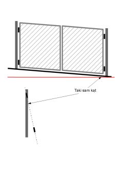
    If you have a gate on a slope then the gate will look like this:

    Diagram of a double-leaf gate on a slope, with hinge axis angle matching the ground’s inclination indicated. .

    The gate wings will not be rectangles but rhombuses.
    The red dash is the horizontal.
    The black dash is the slope of the ground (earth) in the gate.
    You won't have a problem with the right wing at all, because when the wing is open, there will be more space between the end of the wing and the ground than when the gate is closed.
    You only have a problem with the leaf that slopes downwards in the gate, i.e. the left one, because this leaf slopes down and by opening it the gap will decrease.

    In order for this left leaf to be at a constant distance from the ground when opening, the angle of the hinge axis must be at an angle with the ground relative to the horizontal.

    I am assuming, of course, that the cannon only descends in one direction.
    However, if it also slopes inwards or outwards then this must be additionally taken into account in the inclination of the hinge axis. If the land falls inwards, the angle of the hinge axis can be reduced by the angle of the land inwards.
    If the terrain slopes inwards, the angle of the hinges must also be increased by the same angle as the terrain slopes inwards from the door.

    But there is still the option of a roller-lifted bottom. The only disadvantage of this solution is that this raised section will be facing the passage light.
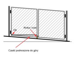
    Alternatively, it could be lifted up by a roller/wheel driving on the ground. If there are cobblestones or concrete, the roller will lift this part of the wing up.

    Diagram of a gate on a slope showing hinge axis, support roller, and the lifted section. .
  • #9 21561088
    rafal222u
    Level 4  
    Ok, I understand the shape of the gate in when closed, I just thought I would make the top edge of both leaves flush in a straight line, not parallel to the ground.
    It is possible that your solution is more aesthetically pleasing and pleasing to the eye.
    Unfortunately the terrain on my plot also rises inwards, I also have to take this into account (side slope and rising slope).
    What set of equipment do you recommend for such an application?
    I would also like to control this "from the outside" of the open/close type and I would like to integrate this with the alarm.... in the event of an intruder alarm activation, lock the gate.
  • #10 21561149
    Plumpi
    Heating systems specialist
    Then maybe actually make the bottom part liftable with a wheel going up the driveway.
    Alternatively, lifting the whole wing upwards. But then there's a bit of fiddling with the actuator mounts, which would have to be fitted with extra joints.
    Here, it would be best to be guided by the angles of the entry plane in each direction.
    In addition, you might still want to consider an outward opening. Then you might avoid such combinations.

    As far as the equipment is concerned, I have already specified this before.
    I have BFT Thalia A80 + Phobos BT B40 actuators at my place.
    In addition, Zamel SBW-02 Supla mobile phone control modules
    4-button remote controls.

    This Thalia A80 controller operates 4 channels for me:
    1 - Opening and closing the gate
    2 - Opening the gate (electric door strike)
    3 - Locking the gate in any position e.g. after opening. It's a useful function when there's a party and guests descend, or when you leave too often and drive into the yard or shovel snow. I have the gate opening programmed in such a way that after opening it closes automatically after 10 seconds. I don't have to remember to close the gate. Of course, standing in the 'light' of the photocells, the gate waits to be exposed and starts counting 10 seconds after the photocells are exposed.
    4 - Gate defrost control.
    In the gate under the wings, across the width of the gate, I have a concrete beam poured and a heating cable sunk into it.
    Everything is operated by this Thalia A80 controller.
    I am mega satisfied.

    I advise against locking the gate during an alarm. You won't stop a thief that way, and you won't escape yourself when you are mugged and have to run away.
    Also, sometimes alarms go off for no reason. If you go to switch it off, you won't open the gate.

    It remains to measure the angles of the slope and then you will know which solution is better.
    Maybe a gate with folding leaves that open outwards.

    From a technical point of view, the easiest way would be to make this bottom section hingeable.
    This part could be tilted by means of an additional rounded guide (cam) and a roller mounted to this moving part.
  • #11 21561166
    rafal222u
    Level 4  
    Outside I have a pedestrian walkway straight away, also not very.
    I could move the gate back a few metres so it opens outwards, but I lose driveway space that way.
    I was also thinking of an accordion gate that would go around the curve, corner of the plot, but this is probably the most expensive solution.

    I haven't exactly measured the slope of the land to the inside of the driveway, but by eye it will be about 25 cm. Can that much be achieved using only angled hinges?
  • ADVERTISEMENT
  • #12 21561186
    Plumpi
    Heating systems specialist
    rafal222u wrote:
    I've also thought about a folding gate that would ride on the hatch, corner of the plot, but this is probably the most expensive solution.


    Such a solution would not pass the test in our climate.

    Have you thought about a single-leaf, bifold gate?
  • #14 21561342
    Plumpi
    Heating systems specialist
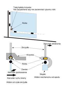
    Well, this is exactly the solution with the hinged lower part, guided by a roller, I wrote to you earlier, instead of lifting this lower part with an actuator. Only, as I mentioned before, the disadvantage is that this lower part enters the "light" of the door.
    If you don't mind, this would be the simplest mechanism to implement.

    But there is also the possibility to make this part lift the other way. You need a suitable cam along which the roller on the lever will move.


    Diagram of a gate mechanism lifting the lower part with a cam and roller, including labeled components. .

    I hope the drawings are clear enough to understand the principle of operation.
    The cam would lift this lower part of the wing in the same direction in which the wing would move.
    The advantage of this solution over the one shown in the video is that the lower part would not be able to be lifted when the door is closed, because the cam blocks this possibility.
    In the case of the solution shown in the film, the lower part can be lifted easily when the door is closed. Of course, for a thief such a gate is no protection, but, for example, a child playing in the yard or a dog, for example, could come out into the street.
    I also wrote to you earlier about such a cam solution.
    The cam must be shaped like a section of a circle/circle on which the roller moves.
  • #15 21561418
    rafal222u
    Level 4  
    I understand your solution with the cam.
    In this solution with the wheel, theoretically you could add some kind of bolt that would lock this lower part during the closed position?

Topic summary

The discussion focuses on selecting a control system for an automatic double-leaf gate installed on a significant side slope, which complicates the use of standard straight gates. The main challenge is enabling one leaf, positioned higher on the slope, to open inward while its lower part lifts upward to clear the uneven terrain. Two primary mechanical solutions are considered: (1) using angled and offset hinges to allow the leaf to lift naturally during opening, requiring the leaf to be trapezoidal to match the slope, and (2) employing an additional actuator to lift the lower part of the leaf independently. The angled hinge solution is simpler, more aesthetically pleasing, and has been successfully implemented with hinge offsets corresponding to the slope angle, lifting the gate end by several centimeters. The actuator-based solution is more complex and less common, with no widely available kits for a third actuator, but can be managed via gate controllers with auxiliary outputs. Additional mechanical designs include a cam and roller mechanism to lift the lower leaf part, which can be locked in the closed position for security. Equipment recommendations include BFT brand actuators (Thalia A80 controller and Phobos BT B40 actuators) combined with Zamel SBW-02 Supla mobile control modules and 4-button remotes, supporting multi-channel control including locking and integration with alarm systems. Alternatives such as sliding gates or bifold gates are discussed but may be unsuitable due to terrain or slope severity. The importance of precise geometric alignment of hinges and leaf shape to maintain consistent ground clearance during operation is emphasized.
Summary generated by the language model.
ADVERTISEMENT