logo elektroda
logo elektroda
X
logo elektroda

[BK7231N] [CBU] Ligency RGBW+IC LED Spotlights GPIO Identification After Flashing

pborrelli 1671 6
ADVERTISEMENT
  • Hi all! I just got two of these outdoor addressable LED Spotlights (RGBW+IC) that use a CBU. Disassembly was a bit destructive and cracked the case that held the circuit board, but it'll still be usable when it's done.
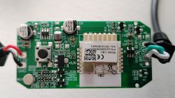
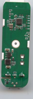
    Photo of a circuit board with a CBU module and electronic components.
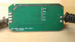
    Circuit board of JBT-WF1-XC004-YWY module with pin labels
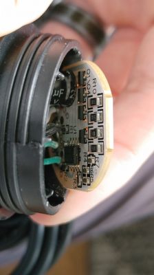
    Close-up of a circuit board with markings and LED lights.
    Close-up of a circuit board with electronic components.
    I was successfully able to backup the factory firmware (attached) and install OpenBeken using BK Flasher, but haven't been able to make much progress since then. I can't seem to figure out how the GIPOs control the lights. I used the GPIO doctor on all the pins, but none will cause the lights to light up in any way (they did work before I flashed OpenBeken). I've only been able to identify that P24 is the button by using the "Set Input P-up," and pressing the button to see the change. Other than that, I am hitting a wall.
    Text Description
    Device configuration, as extracted from Tuya: 
    - Microphone (TODO) on P23
    - SPI MISO17
    - SPI MOSI16
    Device seems to be using CBU module, which is using BK7231N.
    And the Tuya section starts, as usual, at 2023424
    
    JSON Format:
    {
    	"Jsonver":"1.0.0",
    	"brightmin":"10",
    	"gmwb":"75",
    	"title20":"1",
    	"gmwg":"70",
    	"knum":"1",
    	"wfcfg":"spcl_auto",
    	"colormin":"10",
    	"pmemory":"1",
    	"gmkb":"60",
    	"k1sfunc":"5",
    	"cmod":"4",
    	"lednum":"12",
    	"netlptime":"3",
    	"micpin":"23",
    	"rstbr":"50",
    	"musicfunc":"1",
    	"colormax":"100",
    	"module":"CBU",
    	"cwmaxp":"100",
    	"rstmode":"1",
    	"k1lfunc":"1",
    	"dmod":"7",
    	"brightmax":"100",
    	"speedstep":"20",
    	"wfct":"3",
    	"expowctrl_pin":"8",
    	"defbright":"100",
    	"rstnum":"3",
    	"rstcor":"r",
    	"key1_pin":"24",
    	"sensimax":"300",
    	"miso":"17",
    	"mosi":"16",
    	"keyfunc":"1",
    	"irfunc":"0",
    	"expowctrl_lv":"1",
    	"adclimit":"2400",
    	"sensimin":"30",
    	"MISO":"17",
    	"wt":"20",
    	"key1_lv":"0",
    	"brightstep":"20",
    	"remdmode":"0",
    	"colorpfun":"0",
    	"CS":"15",
    	"gmwr":"100",
    	"gmkg":"60",
    	"onoffmode":"1",
    	"colororder":"0",
    	"brightrate":"20",
    	"lptime":"3",
    	"aging":"0",
    	"category":"1101",
    	"SCL":"14",
    	"gmkr":"80",
    	"defcolor":"r",
    	"crc":"107",
    	"}cPhAgw_di{abi":"0",
    	"id":"null",
    	"swv":"1.0.20",
    	"bv":"40.00",
    	"pv":"2.2",
    	"lpv":"3.4",
    	"pk":"keyfwt38nejumpuv",
    	"firmk":"keyfwt38nejumpuv",
    	"cadv":"1.0.5",
    	"cdv":"1.0.0",
    	"dev_swv":"1.0.20",
    	"s_id":"null",
    	"dtp":"0",
    	"sync":"0",
    	"attr_num":"1",
    	"mst_tp_0":"9",
    	"mst_ver_0":"1.0.20",
    	"mst_tp_1":"0",
    	"mst_ver_1":"null",
    	"mst_tp_2":"0",
    	"mst_ver_2":"null",
    	"mst_tp_3":"0",
    	"mst_ver_3":"null } )Agw_wsm{nc_tp",
    	"ssid":"null",
    	"passwd":"null",
    	"md":"0",
    	"random":"0",
    	"wfb64":"1",
    	"stat":"0",
    	"token":"null",
    	"region":"null",
    	"reg_key":"null",
    	"dns_prio":"0 }{uuid",
    	"psk_key":"MnXfZutokIqrbtJmhnyMq6P1A0fcXxvuXcRmO",
    	"auth_key":"tAOi6vMDmHSZ7VN7CvmGSE3IFbjv0AEi",
    	"ap_ssid":"SmartLife",
    	"ap_passwd":"null",
    	"country_code":"null",
    	"bt_mac":"null",
    	"bt_hid":"null",
    	"prod_test":"false",
    	"fac_pin":"q8es5qukiuljknuj }{nc_tp",
    	"lckey":"null",
    	"h_url":"null",
    	"h_ip":"null",
    	"hs_url":"null",
    	"hs_ip":"null",
    	"hs_psk":"null",
    	"hs_psk_ip":"null",
    	"mqs_url":"null",
    	"mqs_ip":"null",
    	"mq_url":"null",
    	"mq_ip":"null",
    	"ai_sp":"null",
    	"ai_sp_ip":"null",
    	"mq_psk":"null",
    	"mq_psk_ip":"null",
    	"lp_url":"null",
    	"lp_ip":"null",
    	"time_z":"null",
    	"s_time_z":"null",
    	"wx_app_id":"null",
    	"wx_uuid":"null",
    	"dy_tls_m":"0",
    	"cloud_cap":"0",
    	"psk21_key":"null }{nc_tp"
    }
    

    I did find out from the backup that BK Flasher identified the use of SPI, MOSI, and MISO. You'll have to forgive me, as that is getting beyond my level of knowledge and it's a bit of a foreign language. I did my best to trace out the pins on the board and what components they are connected to. Here's what I found:
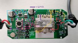
    Circuit board with CBU module and labeled pins and pathways.
    I've spent the past three days reading and learning; these threads seem similar to my device:
    [BK7231N/CBU] Casa Life ALDI Aus - Floor Lamp Mood Lamp - RGB control, SPI? MOSI? MISO?
    Deciphering Pin Configuration & JSON Readout for Marlrin RGBCW Corner Floor Lamp (MOSI/MISO)
    [BK7231N - CBU] Teardown of Aldi (Australia) CasaLux Smart Led Corner Lamp
    If there's any recommendations or literature that informs how to make this work, please let me know. I've been searching, but haven't found the solution yet.

    Cool? Ranking DIY
    About Author
    pborrelli
    Level 3  
    Offline 
    pborrelli wrote 10 posts with. Been with us since 2022 year.
  • ADVERTISEMENT
  • #2 20911963
    p.kaczmarek2
    Moderator Smart Home
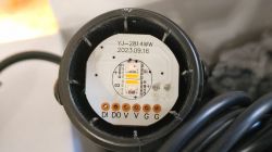
    This looks like individually adressable LEDs, the DO (Data Out) marking also indicates this. Have you tried our experimental SPI driver?
    
    1. Start driver
    startDriver SM16703P
    
    2. Init Driver - replace 64 with number of LEds
    SM16703P_Init 64
    
    3. Set Pixel
    SM16703P_SetPixel 1 255 0 0
    SM16703P_SetPixel 2 0 255 0
    SM16703P_SetPixel 3 0 0 255
    
    4. Start Output (each call will trigger one)
    SM16703P_Start


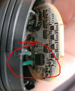
    What is the marking here:
    Close-up of a circuit board fragment with visible electronic components and traces. A marked area with the DO (Data Out) label.
    Helpful post? Buy me a coffee.
  • ADVERTISEMENT
  • #3 20912759
    pborrelli
    Level 3  

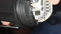
    You Sir are a genius and a saint! I ran the SPI Driver commands and got light! Two of the four lit up, one blue and the other white. I then powered it down to get a picture of the chip on the LED board:
    Close-up of WS2814A chip on a PCB board.
    It appears to be WS2814A LEDs ... ? Again, I'm out of my league here.
    Problem now is I can't get it to light up again after powering down and back up. I set everything back the way it was, but rerunning the SPI Driver commands is doing nothing now. What am I missing?
    I've set the GPIOs P8, P15, and P16 to be PWMs or Relays, but nothing appears to be working. What are the recommended GPIO settings for the SPI Driver? I'm going to keep tweaking with it, but it's got me scratching my head at the moment.
    Thank you again @p.kaczmarek2 I don't know how you keep on top of all the posts in this forum, as well as the modifications to the firmware!
  • #4 20912797
    p.kaczmarek2
    Moderator Smart Home
    WS2814A ... well, to be honest, it's the first time ever I see this chip, but it bears a significant resemblance to WS2812 LEDs.

    Let's check the datasheet:
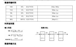
    Timing diagram and connection layout of WS2814A circuit.
    Timings are similiar... but frame is 32 bit, and not 24 bit like WS2812B.

    This would require some adjustements to our driver, but still, our driver should theoretically at least be able to lit some random colors on that....

    Futher testing might be needed, but it would require hooking an oscilloscope to the DO pin.

    Alternatively, can you try:
    
    SM16703P_Init 4
    SM16703P_SetPixel 0 255 255 255
    SM16703P_SetPixel 1 255 255 255
    SM16703P_SetPixel 2 255 255 255
    SM16703P_SetPixel 3 255 255 255
    

    don't forget to start the driver as well.

    Do not set any GPIO role for P16, just start driver, and run the commands I gave.
    Helpful post? Buy me a coffee.
  • ADVERTISEMENT
  • #5 20912961
    pborrelli
    Level 3  
    Good to know that it's new equipment, and not just that I'm new.
    I cleared the assignment on P16 and did some poking and prodding and am finally getting somewhere. P8 & P15 are set to relays, and I have to toggle either or both on to get light output.
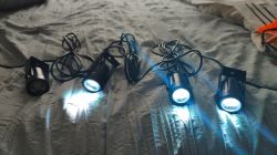
    The first three of the four spotlights turn on with a blue light (They go 1 to 4 from RIGHT to LEFT).
    Four LED spotlights with cables on a bed, three of which emit blue light.
    I plan to do more testing by changing the parameters, but work is starting to get in the way of play!
    There was one error, but I still got light when starting the output:
    (startDriver SM16703P)
    Info:MAIN:Started SM16703P.
    Info:CMD:[WebApp Cmd 'startDriver SM16703P' Result] OK
    ...
    (SM16703P_Init 4)
    Info:CMD:Register driver with 4 LEDs
    Info:CMD:[WebApp Cmd 'SM16703P_Init 4' Result] OK
    ...
    (SM16703P_SetPixel 0 255 255 255)
    Info:CMD:Set Pixel 0 to R 255 G 255 B 255
    Info:CMD:Raw Data 0xee 0xee 0xee 0xee - 0xee 0xee 0xee 0xee - 0xee 0xee 0xee 0xee
    Info:CMD:[WebApp Cmd 'SM16703P_SetPixel 0 255 255 255' Result] OK
    ...
    (SM16703P_SetPixel 1 255 255 255)
    Info:CMD:Set Pixel 1 to R 255 G 255 B 255
    Info:CMD:Raw Data 0xee 0xee 0xee 0xee - 0xee 0xee 0xee 0xee - 0xee 0xee 0xee 0xee
    Info:CMD:[WebApp Cmd 'SM16703P_SetPixel 1 255 255 255' Result] OK
    ...
    (SM16703P_SetPixel 2 255 255 255)
    Info:CMD:Set Pixel 2 to R 255 G 255 B 255
    Info:CMD:Raw Data 0xee 0xee 0xee 0xee - 0xee 0xee 0xee 0xee - 0xee 0xee 0xee 0xee
    Info:CMD:[WebApp Cmd 'SM16703P_SetPixel 2 255 255 255' Result] OK
    ...
    (SM16703P_SetPixel 3 255 255 255)
    Info:CMD:Set Pixel 3 to R 255 G 255 B 255
    Info:CMD:Raw Data 0xee 0xee 0xee 0xee - 0xee 0xee 0xee 0xee - 0xee 0xee 0xee 0xee
    Info:CMD:[WebApp Cmd 'SM16703P_SetPixel 3 255 255 255' Result] OK
    ...
    (SM16703P_Start)
    Error:CMD:before enable tx 0x0000320c
    Error:CMD:enable tx 0x0000320c
    Info:CMD:[WebApp Cmd 'SM16703P_Start' Result] OK

    Light output is ... interesting. Sometimes when entering the Start command, I may only get two of the lights, and one was warm white one time. If I mess with the toggle buttons on the main console, the lights will sometimes turn off without turning back on. Also, if I enter the commands and try to start the lights before toggling on the relays, it won't work.
    It's exciting to get somewhere with these. I'm happy to do more testing and tuning, is there a writeup on the SPI Driver?(nevermind, I found them). I'll go do some things and report back the findings, not sure how much I can do because of the 32 bit frame, but I'm going to play anyway.
  • ADVERTISEMENT
  • #6 20915260
    pborrelli
    Level 3  

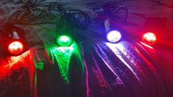
    I've been doing some testing and tuning, but not much to report. I can get all four lights to light up by playing with various settings on the number of pixels and the color assignment going to each one, but there's no pattern or predictability to them. This is of course due to the 24 vs 32 bit data packaging.
    I wish I knew how to write C, I'd be happy to make adjustments. That's well above my pay grade.
    In the meantime, I'm happy to do more testing, and when this is up and running properly I'll do a full teardown write-up.
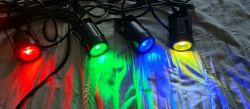
    Four spotlights emitting different colors: red, green, blue, and white, placed on a dark background.
  • #7 21192339
    pborrelli
    Level 3  
    So it's been most of a year now, these sat for about seven months, but I finally picked them up again.

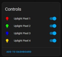
    I found a workaround that provides correct color and individual control of each LED; though it's with ESPHome and not OpenBeken. It turns out the WS2814 are known to be a variant of the SK6812 with a white channel. I was able to use the "Beken_SPI_LED_Strip" platform in ESPHome and set the chipset option to "sk6812" and the color option "is_wrgb" to "True." This set the correct color on each led and and allowed individual control. I think having a data packet for the white channel pushed the correct 32bit full data packet and corrected the problem.

    I don't know if there's a way to leverage this in OpenBeken, but it could be a quick workaround for using WS2814 LEDs.
    Control panel with options for four uplight pixels, each with an individual toggle switch.

    Four LED spotlights emitting light in red, green, blue, and yellow colors.

Topic summary

The discussion revolves around the identification and control of GPIOs for Ligency RGBW+IC LED Spotlights after flashing with OpenBeken firmware. The user successfully backed up the factory firmware and installed OpenBeken but faced challenges in controlling the lights via GPIOs. Initial attempts using the SPI driver commands yielded partial success, lighting up some LEDs but not consistently. The LEDs were identified as WS2814A, which are similar to WS2812 but require different data packet configurations. After further testing, the user found that using ESPHome with the "Beken_SPI_LED_Strip" platform allowed for correct color and individual control of each LED by setting the chipset option to "sk6812" and enabling the white channel. This workaround provided a solution to the control issues experienced with OpenBeken.
Summary generated by the language model.
ADVERTISEMENT