logo elektroda
logo elektroda
X
logo elektroda
Dostępna jest polska wersja

Czy wolisz polską wersję strony elektroda?

Nie, dziękuję Przekieruj mnie tam

Identifying RTL Wi‑Fi module in TP-Link Tapo P105, pinout vs ESP-02S

madlac1971 39 4
ADVERTISEMENT
  • #1 21878524
    madlac1971
    Level 6  
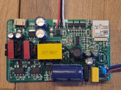
    Anyone has info on this RTL board? It's from a Tapo P105 plug. Any info much appreciated.
    Unfortunately the pin-out doesn't seem to match ESP-02S :(.

    Green printed circuit board with electronic components and a central cutout revealing a black ribbon Close-up of a small PCB with an integrated circuit and surface-mount components Small green PCB with printed numbers, circuit traces, and four silver contacts along the bottom edge
  • ADVERTISEMENT
  • #2 21878561
    divadiow
    Level 38  
    not seen that one around I don't think. Do you have a multimeter? could do with tracing to which pins each of the TP pads go to on the RTL8720CF

    Pinout diagram of RTL8720CF-VA1 IC with a crab-like logo and labeled pins around the package
  • ADVERTISEMENT
  • #3 21878573
    madlac1971
    Level 6  
    >>21878561

    Multimeter is not a problem, my eyesight is :(.
    It seems it's being fed with 5 V.
  • ADVERTISEMENT
  • #4 21878585
    divadiow
    Level 38  
    5v - seems that is acceptable for RTL8720CF

    Excerpt of a Realtek Ameba‑Z II datasheet table showing power pins and voltage notes
  • #5 21878639
    madlac1971
    Level 6  
    >>21878561

    It was easier than expected. Should be enough to flash it, thx for the idea. I'll update when I know, unless I release the smoke reserves from the chip LOL.
    TP1 - Vcc, TP8 - Gnd
    TP6 - GPIOA_0, TP9 - 36 (GPIOA_15 UART_Log_RXD), TP7 - 37 (GPIOA_16 UART_Log_TXD)
    TP10 - possibly GPIOA_13 RX
    If I read it correctly, TP6 and 10 go to VCC for flashing.
ADVERTISEMENT