logo elektroda
logo elektroda
X
logo elektroda

Tapo P100 (RTL8720CF) Boot Log and Resource Details

divadiow 1422 6
ADVERTISEMENT
  • #1 21349522
    divadiow
    Level 35  
    >>21346711

    I had given someone a Tapo P100 which is RTL8720CF, so nabbed that back (swapped with Beken device). Here's some resources relating to the P100. New post rather than make a distraction in the development thread.
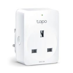
    Tapo P100 smart plug with tapo logo and LED indicator.

    Boot
    Code: Text
    Log in, to see the code

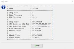
    Chip information displayed in a table on a computer screen.

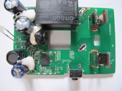
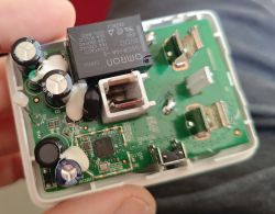
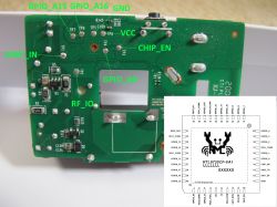
    Circuit board of Tapo P100 with RTL8720CF chip and capacitors. PCB with markings and electronic components. Close-up of an electronic circuit with a visible RTL8720CF chip.

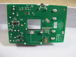
    Close-up of the internal electronics of a Tapo P100 device.

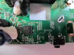
    Tapo P100 PCB with connector and pin labels.


    Screenshot of firmware version 1.3.7 Build 20230711 Rel. 61904.
  • ADVERTISEMENT
  • #2 21349955
    divadiow
    Level 35  
    Code: JSON
    Log in, to see the code


    RELAY - PA8
    BTN - PA17
    LED_N - PA10

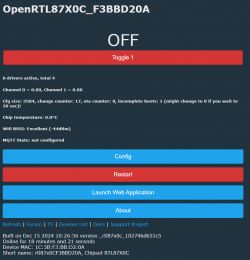
    Screenshot of the OpenRTL87X0C software interface with the toggle switch turned off.
  • ADVERTISEMENT
  • #3 21369371
    zombo6
    Level 1  
    >>21349955 .
    I also have Tapo P100 but EU version, and the board is a bit different. But I have a few questions regarding the flashing connection scheme.
    Would you mind sharing your connection setup for flashing the chip?
    I'm assuming that PA15 and PA16 go to TX and RX.
    What about PA0? I've read somewhere it should go to 3v3.
    And should I put C_EN to GND while booting to put it in download mode?
  • #4 21369606
    divadiow
    Level 35  
    yes to PA15/16 and I pulled PA00 high with direct connection to 3.3V. I did not need to use CEN - just powered on with PA00 connected.
  • ADVERTISEMENT
  • Helpful post
    #5 21375478
    p.kaczmarek2
    Moderator Smart Home
    Helpful post? Buy me a coffee.
  • #6 21423967
    divadiow
    Level 35  
    Code: Text
    Log in, to see the code
  • ADVERTISEMENT
  • Helpful post
    #7 21566999
    divadiow
    Level 35  
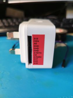
    This is more useful. Some GPIOs not seen on RTL8720CF modules I have. Not for use with the mains of course.
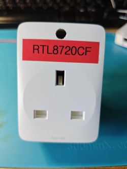
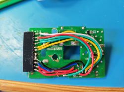
    An electronic adapter with a plug and a pin header labeled on a red sticker White electrical plug with a red label RTL8720CF. Printed circuit board with soldered colorful wires on a blue surface.

Topic summary

The discussion centers on the Tapo P100 smart plug, specifically the RTL8720CF chip variant. Key resources include boot logs showing the Realtek RTL8710c IoT platform initialization, bootloader messages, and RAM start details. The device uses GPIO pins PA8 for relay control, PA17 for the button, and PA10 for the LED indicator. Flashing the chip involves connecting PA15 and PA16 to TX and RX respectively, with PA0 pulled high to 3.3V to enter download mode without needing to manipulate the C_EN pin. Partition table details reveal firmware offsets and encryption keys. Additional images provide PCB layouts and GPIO mappings, noting some GPIOs are not present on all RTL8720CF modules. The EU version of the P100 has a slightly different board layout. Related flashing guides for similar Realtek-based devices (WBR2, WBR3, WBRU, W701-VA2-CG) are referenced for Home Assistant integration.
Summary generated by the language model.
ADVERTISEMENT