Hi everyone, I bought a garage door opener from Avatto GDS16:
![[CBU/BK7231N] AVATTO GDS16 WiFi relay module - Sensor Problem](https://static.elektroda.pl/attach/1278181/thumb/case_2689033.jpg "[CBU/BK7231N] AVATTO GDS16 WiFi relay module - Sensor Problem") case.png (5.23 MB)You must be logged in to download this attachment.
case.png (5.23 MB)You must be logged in to download this attachment.
![[CBU/BK7231N] AVATTO GDS16 WiFi relay module - Sensor Problem](https://static.elektroda.pl/attach/1278182/thumb/side_1_1854015.jpg "[CBU/BK7231N] AVATTO GDS16 WiFi relay module - Sensor Problem") side_1.png (5.58 MB)You must be logged in to download this attachment.
side_1.png (5.58 MB)You must be logged in to download this attachment.
![[CBU/BK7231N] AVATTO GDS16 WiFi relay module - Sensor Problem](https://static.elektroda.pl/attach/1278183/thumb/back_1_4117202.jpg "[CBU/BK7231N] AVATTO GDS16 WiFi relay module - Sensor Problem") back_1.png (5.32 MB)You must be logged in to download this attachment.
back_1.png (5.32 MB)You must be logged in to download this attachment.
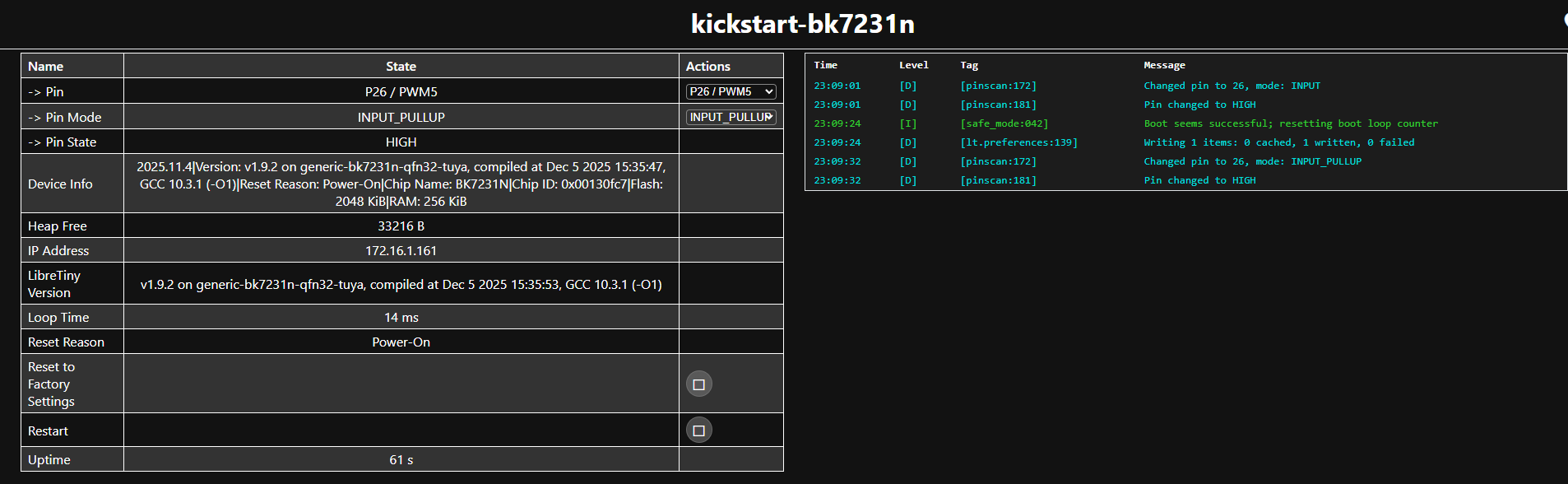
I was able to get the original firmware and get the info below:
After that, flashing the ESPhome kickstart firmware was easy.
The relay and the LED work fine, no problem at all, but I was not able to make the sensor pin work.
I try to mark the pin as an input_pullup and other pins as well, but nothing works.
I have two of it and the result is the same for both.
Can someone help me figure this out?
This is the code that I use:
![[CBU/BK7231N] AVATTO GDS16 WiFi relay module - Sensor Problem](https://static.elektroda.pl/attach/1278181/case_2689033.png "[CBU/BK7231N] AVATTO GDS16 WiFi relay module - Sensor Problem") case.png (5.23 MB)You must be logged in to download this attachment.
case.png (5.23 MB)You must be logged in to download this attachment.
![[CBU/BK7231N] AVATTO GDS16 WiFi relay module - Sensor Problem](https://static.elektroda.pl/attach/1278182/side_1_1854015.png "[CBU/BK7231N] AVATTO GDS16 WiFi relay module - Sensor Problem") side_1.png (5.58 MB)You must be logged in to download this attachment.
side_1.png (5.58 MB)You must be logged in to download this attachment.
![[CBU/BK7231N] AVATTO GDS16 WiFi relay module - Sensor Problem](https://static.elektroda.pl/attach/1278183/back_1_4117202.png "[CBU/BK7231N] AVATTO GDS16 WiFi relay module - Sensor Problem") back_1.png (5.32 MB)You must be logged in to download this attachment.
back_1.png (5.32 MB)You must be logged in to download this attachment.
I was able to get the original firmware and get the info below:
I: UPK: Found BK7231N config!
I: UPK: Switch/plug config
I: UPK:  - relay 1: pin P6
I: UPK:  - button 1: pin P26
I: UPK: Status LED: pin P9, inverted False
ADVERTISEMENT
After that, flashing the ESPhome kickstart firmware was easy.
The relay and the LED work fine, no problem at all, but I was not able to make the sensor pin work.
I try to mark the pin as an input_pullup and other pins as well, but nothing works.
I have two of it and the result is the same for both.
Can someone help me figure this out?
This is the code that I use:
Code: JSON