FAQ
TL;DR: A 15 mA bias per device lets this push-pull Dynalo deliver 160 mW into 32 Ω while "none of the transistors will be cut off" [Elektroda, OTLamp, post #16628247] Purists debate terminology, but measured currents confirm pure Class A operation.
Why it matters: true Class A minimises crossover distortion at headphone-safe levels.
Quick Facts
• Quiescent current: 15 mA × 4 output transistors = 60 mA total [Elektroda, OTLamp, post #16628247]
• Pure-Class-A power window: up to 160 mW @ 32 Ω load [Elektroda, OTLamp, post #16628247]
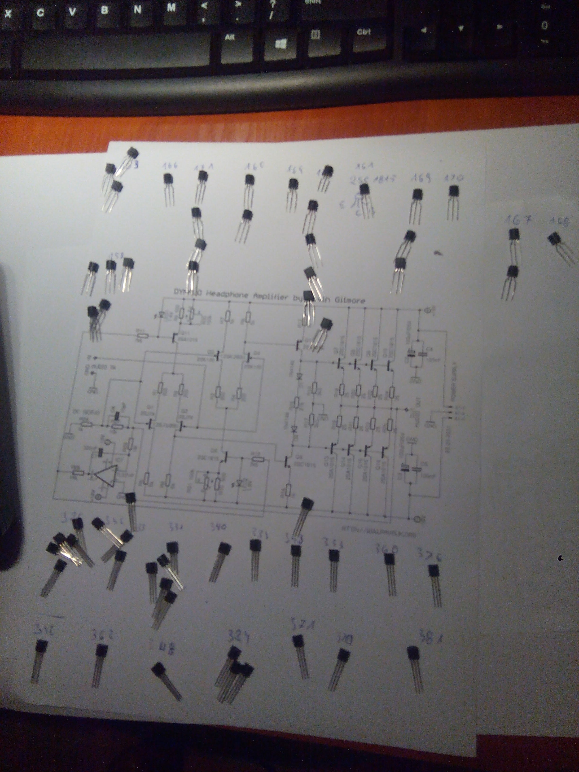
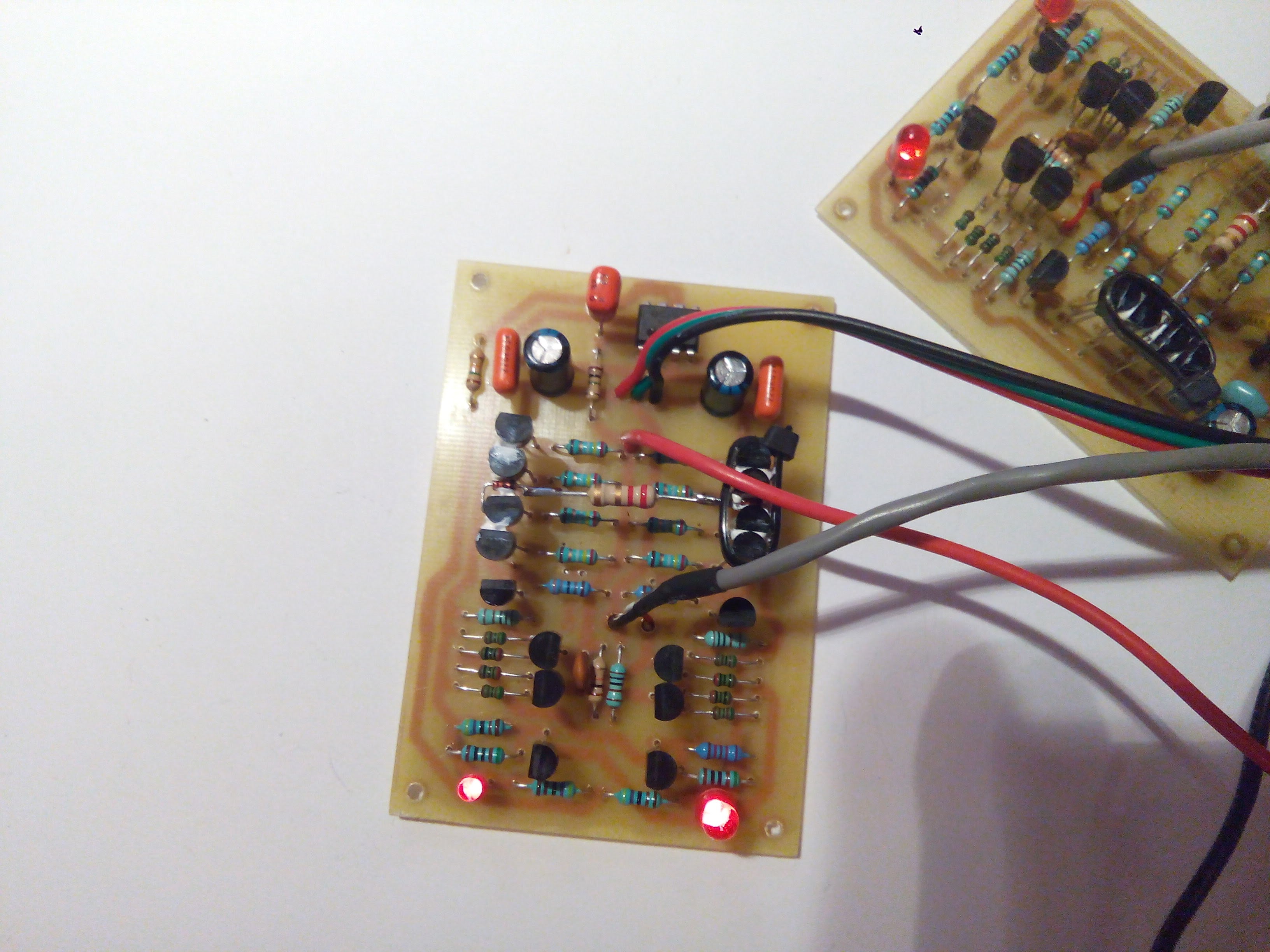
• Output devices used: 2SA1015 & 2SC1815 (PLN 0.50/0.30 each) [Elektroda, Hetii, post #16696001]
• J-FET substitutes: 2SJ103 / 2SK246 replace 2SJ109 / 2SK389 [Elektroda, Hetii, post #16696001]
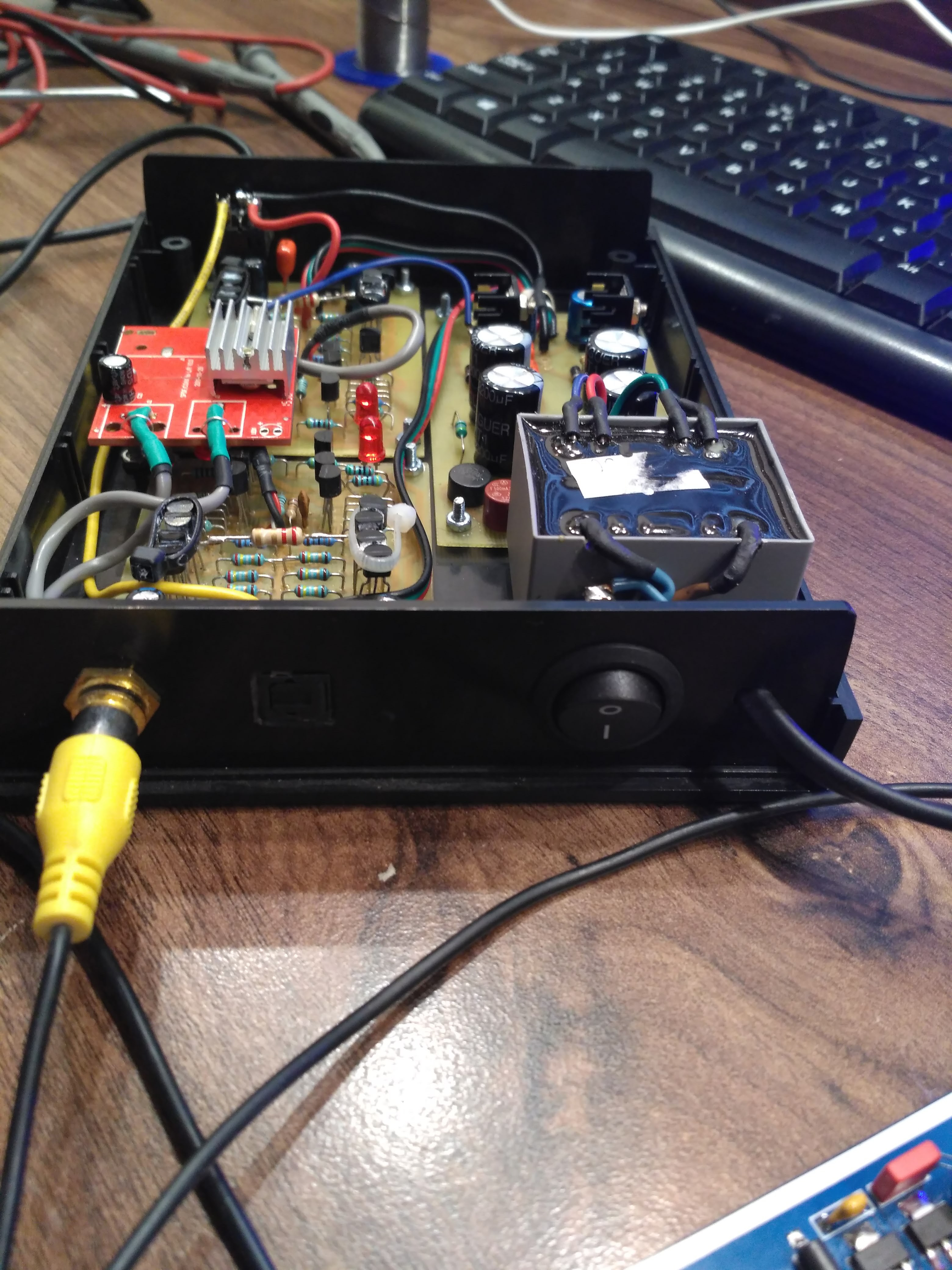
• Enclosure: Z-112 aluminium case, passively cooled [Elektroda, Hetii, post #16623193]
What makes this build “pure” Class A?
In Class A no device reaches cutoff during any signal instant. With 60 mA total idle current the amp can swing 100 mA peak before either half turns off, giving 160 mW into 32 Ω fully within Class A
[Elektroda, OTLamp, post #16628247]
Does a push-pull schematic automatically mean AB class?
No. Operating class depends on bias, load and supply voltage, not topology. A push-pull stage biased high enough, as here, remains in Class A over its intended power range
[Elektroda, OTLamp, post #16628247]
Is a current source plus single transistor required for Class A?
That arrangement is common but not mandatory. "Pure Class A simply means lack of cutoff" regardless of whether the stage is single-ended or push-pull
[Elektroda, OTLamp, post #16624718]
How much power before the amp leaves Class A?
Cutoff begins once branch current exceeds the 60 mA quiescent limit. Into 32 Ω that occurs at roughly 230 mW RMS, so anything below stays in Class A
[Elektroda, OTLamp, post #16628247]
Which transistors were used and where can I buy them?
BJT pair 2SA1015 / 2SC1815 came from AVT for PLN 0.50 and 0.30 each. J-FETs 2SJ103 / 2SK246 replaced the unobtainable matched duals and are widely stocked online
[Elektroda, Hetii, post #16696001]
Why were 2SJ103 and 2SK246 chosen over 2SJ109/2SK389?
Single J-FETs are cheaper and easier to source. Matching them by Idss recreates the dual-device behaviour without audible penalty in this low-current application
[Elektroda, Hetii, post #16696001]
How hot does the Z-112 case run?
At 60 mA idle and ±15 V rails, each channel dissipates about 1.8 W. The aluminium Z-112 warms to roughly 45 °C in free air—safe but noticeable. Add vents if ambient exceeds 30 °C (edge-case thermal runaway risk).
Can I use highly sensitive in-ears safely?
Typical IEMs hit 120 dB SPL at 1 mW [Sennheiser, IE Series Datasheet]. Because the amp can deliver 160 mW, start with the volume at minimum to avoid instant 142 dB peaks that can damage hearing.
3-step: How do I set the bias current?
- Warm up the amp for 10 min with no load.
- Measure voltage across the 1 Ω emitter resistors; adjust trimmer until 15 mV (15 mA) shows on each.
- Re-check after 30 min; readjust if drift exceeds 1 mA.
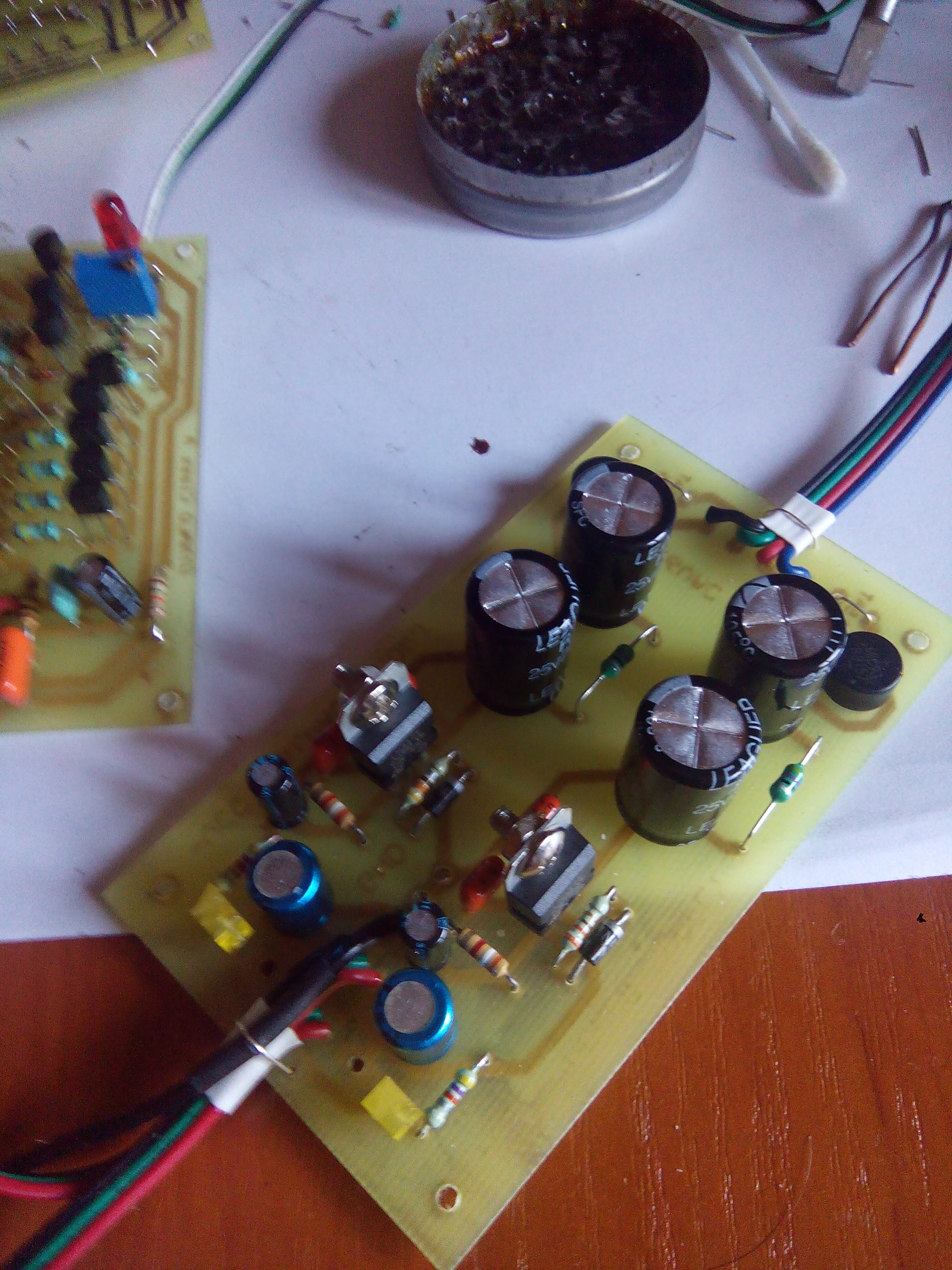
What PCB and layout issues appeared?
The toroidal transformer was bought after boards were etched, leaving mounting mis-aligned; it was later glued to the chassis for stability
[Elektroda, Hetii, post #16624555] Careful mechanical planning avoids such fixes.
How is the USB-to-SPDIF DAC integrated?
A PCM2706 module outputs 24-bit S/PDIF to an external DAC board inside the same enclosure, providing a clean digital front-end without extra cabling
[Elektroda, Hetii, post #16623193]
Common failure: what happens if transistor pairs are poorly matched?
Imbalanced pairs raise even-order distortion and may force one side into early cutoff, effectively downgrading operation to AB class and doubling idle heat generation.
Summary generated by AI based on the discussion content.


Comments
Is class A this should not be a current source + control transistor? [Read more]
The standalone degree can work in class A as much as possible. However, I do not know what the term "pure" means in this case? [Read more]
And such a bit of the word Tile from the English name under which I found this scheme ;) [Read more]
Just "clean" it would seem to me that the transistor + source (for very small powers: transistor + resistor), as in HF And so we have AB more in the direction of A. And recently fashionable in ecology... [Read more]
Plates You did and it was possible to print so badly mounted. Can not you give him a plate? [Read more]
Trafo was purchased after the tiles were made. The author, unfortunately, did not share the project files so that you can edit the tiles, although such a simple change could be made in any pain. Finally... [Read more]
None of these things, the jargon term "pure class A" simply means the lack of even a temporary cut-off of any of the active elements throughout the signal period, in contrast to the systems in shallow... [Read more]
It is an amplifier with a typical power stage design in the AB class. You set a large quiescent current in it (incorrectly calling it in the Polish bias) without changing the basic design of the AB class. Another... [Read more]
I see that not only I do not know the A-class knowledge there. And I thought he had something with eyes. I even signed up to an ophthalmologist for 2050. [Read more]
There is no such thing as a typical power grade design in the AB class. It is a typical construction of the anti-progress power stage. However, the operating class depends not only on the value of the... [Read more]
Here I would argue. Sometimes a passing tram is quieter than the music from the headphones of the person standing next to it. As for the class of work, it is the same as with the amplifier system, EC... [Read more]
@OTLamp - read my post and try to understand what I wrote, without adding my own theory to my opinion about this amplifier. The horse that is - everyone sees; here the amplifier diagram... [Read more]
Is not. This is a typical design of a series anti-parallel amplifier. And that's it. The class has nothing to do with it, the scheme is exactly the same regardless of the class. The fact that most amplifiers... [Read more]
It is strange to make a new destiny - only class A - for a complicated amplifier designed for AB (shallow in A and deep in B). Why? Because in such an amplifier, solutions for overcoming problems (mainly... [Read more]
I do not judge this structure in terms of technology, the appropriateness of using class A, connecting small transistors in parallel, etc. I am not interested in this moment. However, I am opposed to mindless... [Read more]
Power amplifiers can be built, among others as so-called "single ended" and "push-pull". What the author has presented is a typical "push-pull" design. Whether she will work in class A or in class B depends... [Read more]
@OTLamp - stay in your views, but let them have others. Terminology and terminology have been used for several decades in electronics not for the sake of reality, but for the easy determination of things,... [Read more]
Technical disciplines to which electronics belong are not based on views, only on facts. The fact that the amplifier discussed here works in Class A has been demonstrated above (160 mW at load 32 & # 937... [Read more]
Hello, Where did your colleague buy transistors? And at what price? [Read more]