logo elektroda
logo elektroda
X
logo elektroda

A pure Class A headphone amplifier - How to Build

Hetii 18759 20
ADVERTISEMENT
Treść została przetłumaczona polish » english Zobacz oryginalną wersję tematu
  • A pure Class A headphone amplifier - How to Build
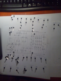
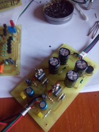
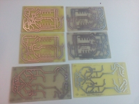
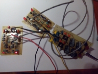
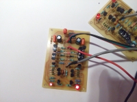
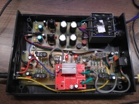
    Some time ago I made myself a pure Class A headphone amplifier. I am not Audiofile, but in my opinion the structure works very nicely, the sound is dynamic and clear. Unfortunately, I don't have oscillograms, however the is no noise.
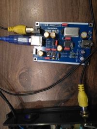
    Over time, the amplifier has developed a DAC that converts the signal from SPDIF into an analog signal, and now tests it with the PCM2706 as a USB->SPDIF converter.
    As for the construction itself, it was a bit of fun with pairing transistors, and in the startup phase with a bias setting, but the general one moved out of the hoof:)
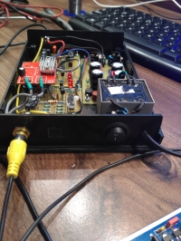
    The whole system was successfully closed in the Z-112 enclosure.
    Project author's website: Dynalo headphone amplifier by Kevin Gilmore
    A pure Class A headphone amplifier - How to BuildA pure Class A headphone amplifier - How to BuildA pure Class A headphone amplifier - How to BuildA pure Class A headphone amplifier - How to Build A pure Class A headphone amplifier - How to BuildA pure Class A headphone amplifier - How to BuildA pure Class A headphone amplifier - How to Build

    Cool? Ranking DIY
    About Author
    Hetii
    Level 17  
    Offline 
    Hetii wrote 503 posts with rating 407, helped 4 times. Live in city Wałbrzych. Been with us since 2003 year.
  • ADVERTISEMENT
  • #2 16623814
    Anonymous
    Anonymous  
  • #3 16623873
    Mark II
    Level 22  
    The standalone degree can work in class A as much as possible. However, I do not know what the term "pure" means in this case?
  • ADVERTISEMENT
  • #4 16624065
    Hetii
    Level 17  
    Mark II wrote:
    I do not know what the term "pure" means in this case?


    And such a bit of the word Tile from the English name under which I found this scheme ;)
  • ADVERTISEMENT
  • #5 16624376
    Anonymous
    Anonymous  
  • #6 16624406
    pier
    Level 24  
    Plates You did and it was possible to print so badly mounted. Can not you give him a plate?
  • #7 16624555
    Hetii
    Level 17  
    pier wrote:
    Tiles You did and it was possible to print so badly mounted. Can not you give it to the plate?


    Trafo was purchased after the tiles were made. The author, unfortunately, did not share the project files so that you can edit the tiles, although such a simple change could be made in any pain.

    Finally it has been glued to the housing and is firmly embedded.
  • #8 16624718
    OTLamp
    Tube devices specialist
    R-MIK wrote:

    I just "read" it would seem to me that transistor + source (for very small powers: transistor + resistor), as in RF. And so we have AB more towards A.


    None of these things, the jargon term "pure class A" simply means the lack of even a temporary cut-off of any of the active elements throughout the signal period, in contrast to the systems in shallow B / AB class (with a significant resting current), in which period, this cut-off, however, occurs. It can be as much as possible in the push-pull system, then for the variable component both active elements (or both branches of these elements) work in parallel on the common load.
    And in HF after all, one transistor + resonant circuit can work as much as possible in class A, AB, B or even C.
  • #9 16628080
    pikarel
    Level 38  
    It is an amplifier with a typical power stage design in the AB class.
    You set a large quiescent current in it (incorrectly calling it in the Polish bias)
    without changing the basic design of the AB class.

    Another Audiovoodoo
  • ADVERTISEMENT
  • #10 16628203
    Anonymous
    Anonymous  
  • #11 16628247
    OTLamp
    Tube devices specialist
    pikarel wrote:
    This is an amplifier with a typical power stage design in the AB class.

    There is no such thing as a typical power grade design in the AB class. It is a typical construction of the anti-progress power stage. However, the operating class depends not only on the value of the quiescent current, but also on the value of the supply voltage, load resistance or even the level of control. For example, a typical AB audio power amplifier powered by, for example, a 30 V symmetrical voltage, in which the transistors have a 50 mA quiescent current, will operate in pure class A with a load resistance greater than 300 Ω none of the transistors will be cut off during the entire signal period.

    Added after 9 [minutes]:

     
    R-MIK wrote:

    I see that not only I do not know the A-class knowledge there.
    And I thought he had something with eyes. I even signed up to the ophthalmologist for 2050.


    I do not know if you have anything with your eyes, but you should think about the fundamentals concerning working classes ... Quiescent current acc. the article used by the thread's author is 15 mA per transistor. There are four transistors in the branches of the push-pull stage, ie the total quiescent current is 60 mA. Each branch will deliver an amplitude less than the quiescent current, say 50 mA, without excessive distortion. Both branches will provide an amplitude of 100 mA, which is based on the load resistance 32 Ω gives an output power of 160 mW. In pure class A, because to such a power will not cut off any branch of the power stage. The cut-off will occur with such control when the current amplitude of each branch exceeds the value of 60 mA, so at power above 230 mW. I doubt anyone would stand up to 160 mW with headphones on.
  • #12 16628317
    Anonymous
    Anonymous  
  • #13 16628330
    pikarel
    Level 38  
    @OTLamp - read my post and try to understand what I wrote, without adding my own theory to my opinion about this amplifier.

    The horse that is - everyone sees; here the amplifier diagram says everything,
    and what quiescent current were set in the amplifier, what was used for it, what was loaded - it is no longer a "pimple".
    Clearly and in Polish I wrote - this is a typical amplifier design for AB class .
  • #14 16628449
    OTLamp
    Tube devices specialist
    pikarel wrote:

    Clearly and in Polish I wrote - this is a typical amplifier design for AB class .


    Is not. This is a typical design of a series anti-parallel amplifier. And that's it. The class has nothing to do with it, the scheme is exactly the same regardless of the class. The fact that most amplifiers in such topology work in the B / AB class do not justify the thoughtless drawing of conclusions from viewing the diagrams.

    Added after 2 [minutes]:

     
    R-MIK wrote:
    .
    As for the class of work, it is the same as with the amplifier system, EC or WC. The same scheme and differences only in the proportions of resistance.

    Well, not only ... Just look at the electrodes from which we take the output signal.
  • #15 16628700
    pikarel
    Level 38  
    It is strange to make a new destiny - only class A - for a complicated amplifier designed for AB (shallow in A and deep in B).
    Why?
    Because in such an amplifier, solutions for overcoming problems (mainly cross-sections) resulting from working in class B were used:
    - to obtain optimal efficiency
    - deep negative feedback and symmetrization of subsequent steps
    used to minimize non-linear distortions introduced by transistors with different conductivities (PNP and NPN, with different characteristics) acting for the negative and positive part of the amplified signal.

    There is no need to perform such procedures in classic A amplifiers - due to the lack of these problems.

    AudioVooDoo - always alive :)

    OTLamp wrote:
    (...) The fact that most amplifiers in such topology work in B / AB class does not justify unthinking drawing conclusions from viewing schemes.

    What you wrote is not only naughty, it's rude;
    when reading such a text, I have the impression that only your conclusions are justified and "thinking".
  • #16 16628768
    OTLamp
    Tube devices specialist
    pikarel wrote:
    It is strange to make a new destiny - only class A - for a complicated amplifier designed for AB (shallow in A and deep in B).
    Why?
    Because in such an amplifier, solutions for overcoming problems (mainly cross-sections) resulting from working in class B were used:
    - to obtain optimal efficiency
    - deep negative feedback and symmetrization of subsequent steps
    used to minimize nonlinear distortions introduced by transistors with different conductivities (PNP and NPN, with different characteristics) acting for the negative and positive part of the amplified signal.


    I do not judge this structure in terms of technology, the appropriateness of using class A, connecting small transistors in parallel, etc. I am not interested in this moment. However, I am opposed to mindless reading of labels, let alone giving them specific arrangement solutions. I think that this is very harmful, especially for beginners, who instead of learning how to analyze the work of the system, will be forced, that like two transistors, it is AB class, and like one transistor and resistor or current source, it is class A.
    pikarel wrote:

    Such procedures do not need to be performed in classic A amplifiers - due to the lack of these problems.

    The very application of class A does not guarantee miraculous parameters, nonlinear problems occur by definition, so a strong feedback is needed anyway.


    pikarel wrote:

    What you wrote is not only naughty, it's rude;
    reading this text I have the impression that only your conclusions are reasonable and "thinking".

    Your complaints in this case, to put it mildly, are fun. Your discontent through which waxes are unnecessarily strewn is widely known here ... For this you are extremely resistant to any translations, even providing concrete evidence put forward does not change anything. And you accuse others of pushing just the right conclusions?
  • #17 16629375
    Pokrentz
    Level 22  
    Power amplifiers can be built, among others as so-called "single ended" and "push-pull". What the author has presented is a typical "push-pull" design.
    Whether she will work in class A or in class B depends only on whether any transistor will ever be clogged or not.
    The push-in power amplifiers work essentially in the AB class, if we increase the output current of the output transistors above the maximum absorbed by the receiver - we will get a "clean" class A. Otherwise it will be an AB class. With a zero-current current, the "pure" class B will come out.
    As we want to have a guarantee of work in class "A", you can use the output stage type "single ended" and set the quiescent current above the maximum collected by the planned load. The "single-ended" system can work in the AB class, but the distortion will be nightmarish and in the "B" class - it will only amplify half (positive or negative) signal.
    The "single-ended" amplifier in class B is used, but as a power supply. Because he does not need to strengthen both halves of the signal - by definition he works on one.
  • #18 16629634
    pikarel
    Level 38  
    @OTLamp - stay in your views, but let them have others.
    Terminology and terminology have been used for several decades in electronics not for the sake of reality, but for the easy determination of things, phenomena, devices, elements and thousands of others, for uniqueness in this terminology.
    It does not suit you - your case, but me and people with a similar opinion, like me - give me a break.

    Only so much and so much.
  • #19 16629786
    OTLamp
    Tube devices specialist
    pikarel wrote:
    @OTLamp - stay in your views, but let them have others.

    Technical disciplines to which electronics belong are not based on views, only on facts. The fact that the amplifier discussed here works in Class A has been demonstrated above (160 mW at load 32 & # 937 ;, and at higher resistance loads, respectively higher). I can not help it, that you can not understand the principle of the counter-current amplifier in class A. Fortunately, there are some who understand. Stay in mindless reading labels and pictures, but do not fool those on the technical forum, because you just lower the level.

    pikarel wrote:

    Terminology and terminology have been used for several decades in electronics not for the sake of reality, but for the easy determination of things, phenomena, devices, elements and thousands of others, for uniqueness in this terminology.


    And that's why you first learn to use them properly, and then teach others. First and foremost, I recommend mastering the basic issues of working classes with particular emphasis on the analysis of the work on the characteristics of the output transistors.

    Added after 25 [minutes]:

     
    Pokrentz wrote:

    The "single-ended" amplifier in class B is used, but as a power supply.


    It has been used even for acoustic frequencies - in applications where non-linear distortions are of little importance, e.g. in alarm sirens. In addition, they are quite common in radio technology, they work as resonant amplifiers in class A, AB, B and C.

    Added after 8 [minutes]:

     
    R-MIK wrote:
    OTLamp wrote:
    I doubt anyone will stand up to 160 mW with headphones on.

    Here I would argue.


    Here you are. The sensitivity of modern headphones is about 120 dB / mW. Can you calculate the sound intensity for 160 mW?
  • #20 16695107
    sylwek_b86

    Level 15  
    Hello,
    Where did your colleague buy transistors? And at what price?
  • #21 16696001
    Hetii
    Level 17  
    sylwek_b86 wrote:
    Hello,
    Where did your colleague buy transistors? And at what price?


    The transistors 2SA1015 and 2SC1815 I bought at the AVT store for the price of 50 and 30 gr / piece.

    Instead of 2SK389 and 2SJ109, I used 2SJ103 and 2SK246.
    Unfortunately, I do not remember where I bought them, but I see that they are available after being entered in google in various stores.

Topic summary

A discussion on building a pure Class A headphone amplifier reveals various opinions on the definition and implementation of Class A versus Class AB amplifiers. Participants debate the characteristics of "pure" Class A, emphasizing that it should not exhibit any cutoff of active elements during the signal period, unlike Class AB. The conversation also touches on the design aspects, including the use of transistors, bias settings, and the importance of quiescent current. The author shares their experience with a DAC and the specific transistors used in their build, while others provide insights into the technical nuances of amplifier classes and the implications of design choices on sound quality.
Summary generated by the language model.
ADVERTISEMENT