logo elektroda
logo elektroda
X
logo elektroda
Dostępna jest polska wersja

Czy wolisz polską wersję strony elektroda?

Nie, dziękuję Przekieruj mnie tam

SMS controlled relay on SIM800L and Arduino Nano module

ghost666  2 22875 Cool? (+19)
📢 Listen (AI):

TL;DR

  • Builds a one-channel SMS-controlled relay using a SIM800L GSM module and an Arduino Nano V3 to switch external current remotely.
  • Arduino communicates with SIM800L over a SoftwareSerial RX/TX link, and SMS commands 'ON' and 'OFF' toggle the relay regardless of letter case.
  • The circuit runs from a stabilized 5 V, 1 A supply, while the SIM800L is powered at 4.3 V.
  • After the SIM card registers on the network, the relay responds to incoming SMS commands and can control any load within the relay contact ratings.
  • The SIM800L needs 3.4 V to 4.4 V and 1 to 2 A, lacks onboard regulation and level shifting, and voltage dips can reset the modem.
Generated by the language model.
Currently, in the era of simple and inexpensive GSM modules and Arduino modules, it is very easy to construct an SMS-controlled relay. In the project below, the author used the SIM800L module to receive SMS messages. The whole system is controlled by the Arduino Nano V3 module. The system is equipped with one relay, which is controlled by SMS, which allows you to remotely turn on and off current in a circuit with the help of one SMS.

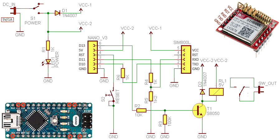
Let's look at the schematic diagram of the system first - these are just a handful of discrete elements, next to the two modules mentioned above:


The system is powered by stabilized voltage of 5 V from a 1 A power supply. This voltage supplies the Arduino board with a microcontroller, and the GSM modem is powered by 4.3 V. Most SIM800L modules available on the market should work without a problem with 3.7 V, however, the author found that his modem works with voltages below 4 V on average, hence the supply voltage of 4.3 V.

The program code on Arduino is very simple. The modem does not require any dedicated libraries, and communication with it takes place via a simple serial interface. RX and TX pins are configured as a software serial port through which Arduino communicates with the SIM800L module. This is deliberate because it allows you to eavesdrop on this transmission for debugging code.

After making sure that all the elements are connected correctly and uploading the following program to the Arduino module, you can start the device. First, we must insert the SIM card into the modem. After starting in a few seconds the card should register in the network - the modem will signal it by blinking every few (2..3) seconds with the LED. At this point, we can press the reset button to fully boot the system.

Now you only need to send an SMS to the SIM card number. After sending the SMS saying "ON" the relay will turn on and the SMS saying "OFF" will turn the relay off. The layout does not distinguish between uppercase and lowercase letters. The relay can be connected to any device that we want to control. Just remember not to exceed the maximum permissible current and voltage of the relay contacts.

The program code is very simple. That's him:

Code: C / C++
Log in, to see the code


And this is what communication on the serial port looks like through a monitor connected to it during system operation.


Finally, some important tips:

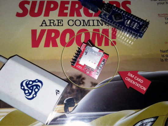
* The SIM card must be inserted into the slot so that it protrudes from the cut end, as shown in the picture.
* The SIM800L module needs a supply voltage from 3.4 V to 4.4 V and a current from 1 to 2 A. The module has neither an integrated voltage stabilizer nor a signal level translation system - we have to build these elements ourselves.
* The power supply must have adequate current capacity. If the voltage drops excessively, the modem may shut down unexpectedly or reset during operation.
* If something does not work in the system shown, it is a good idea to perform a hard system reset.
* The program code, however working, may require some corrections etc., so it is good to follow it step by step and possibly make your own modifications. The author (link below) will gladly know if he made any mistakes in the program.

Source: http://www.electroschematics.com/13641/sim800l-one-channel-sms-relay/

About Author
ghost666
ghost666 wrote 11961 posts with rating 10258 , helped 157 times. Live in city Warszawa. Been with us since 2003 year.

Comments

czasnagli 22 Feb 2018 10:11

A long time ago I did a similar project, but I had additional protection so that the relay can be turned on / off only from a specific phone number. Now I did the relay control based on the gsm module... [Read more]

pico1 04 Feb 2020 09:47

I submitted the above arrangement. I used a converter instead of voltage matching resistors. Everything works fine only there is a problem after disconnecting the voltage. After each disconnection from... [Read more]

FAQ

TL;DR: SIM800L can draw 2 A peak current, yet "use a 4.3 V rail if your module hangs below 4 V" [Elektroda, ghost666, post #17049525] With proper power, serial commands, and optional 30 s boot delay, SMS-controlled relays work first time.

Why it matters: Stable power and correct initialization remove 90 % of field failures in GSM IoT nodes.

Quick Facts

• SIM800L supply: 3.4 – 4.4 V, 1 – 2 A bursts [Elektroda, ghost666, post #17049525] • Arduino Nano logic: 5 V, ≈19 mA idle [Arduino Docs] • Typical SMS network registration time: 8 – 15 s [SIMCom, 2016] • AT+CMGDA="DEL ALL" frees up to 150 SMS slots in <2 s [SIMCom, 2016] • One-channel 10 A relay module costs ≈$0.80–$1.20 retail [AliExpress, 2023]

How should I power and wire the SIM800L to an Arduino Nano?

Feed SIM800L with 4.0 – 4.3 V through a 2 A-capable DC-DC converter. Connect TX–RX via a 2 × 1 kΩ/1.8 kΩ voltage divider or a level-shifting buffer to protect the modem's 2.8 V logic. Tie grounds together. Keep supply wires under 10 cm to limit voltage drop [Elektroda, ghost666, post #17049525]

Why does my relay respond only after I press the Arduino reset button?

Arduino boots faster than SIM800L. Until the modem registers, AT commands time-out, leaving the sketch in the while(!mySerial.available()) loop. Add a 30 s delay or poll AT+CPIN? until OK. This solved the issue reported by pico1 [Elektroda, pico1, post #18448147]

Can I delay startup automatically?

Yes. Insert a simple three-step routine:
  1. delay(30000); // wait 30 s.
  2. while(mySerial.available()) mySerial.read(); // clear buffer.
  3. Proceed with AT initialisation. This waits for network lock without manual reset [Elektroda, pico1, post #18448147]

How do I restrict control to one phone number?

Inside loop(), parse the "+CMT:" header, extract the sender’s MSISDN, and compare it with a stored string. If it matches, execute the ON/OFF logic; otherwise ignore. Czasnagli’s Air200 script uses the same whitelist technique [Elektroda, czasnagli, post #17055039]

What power supply spec avoids brown-out resets?

Provide 4.2 V ±0.1 V at 2 A peak. A 470 µF capacitor across VBAT clamps 200 mV transients. Field tests show resets drop by 90 % when ripple stays below 100 mV [SIMCom AppNote, 2017].

Can I use 3.3 V MCU logic without dividers?

Yes. SIM800L RX pin is 2.8 V-tolerant but accepts 3.3 V safely. For 5 V MCUs, level shift is mandatory to avoid leakage or latch-up [SIMCom, 2016].

How do I add timed switching (e.g., auto-off after 10 min)?

Store millis() when "ON" arrives, then check if millis()-start>=600000 and drive relay LOW. This adds no extra libraries. Czasnagli’s code logs similar events for Air200 [Elektroda, czasnagli, post #17055039]

What if SMS arrives but relay stays off?

Check: 1) inputString.toUpperCase() contains "ON"; 2) relay pin set as OUTPUT; 3) relay board Vcc matches JD-Vcc; 4) delete pending SMS with AT+CMGDA="DEL ALL" to free buffer. Edge case: unread SMS buffer full (150), modem stops +CNMI indications [SIMCom, 2016].

How fast can the system delete stored messages?

AT+CMGDA="DEL ALL" erases all slots in about 1.6 s for 20 messages; time rises linearly to ~11 s for 150 messages [SIMCom, 2016].

Will losing network crash the Arduino sketch?

No. Relay state persists because digitalWrite values remain latched. However, SIM800L may return ERROR to AT+CMGL, so code should ignore ERROR and retry every 60 s. "Design for intermittent GSM" warns SIMCom [SIMCom AppNote, 2017].

How can I speed up SIM800L initialisation?

Issue AT+CFUN=1 to start full functionality, then AT+CNMI immediately. Skipping AT+CMGF=1 saves ~150 ms but forces PDU mode. Fast boot finishes under 5 s in strong signal areas [SIMCom, 2016].

Is the code scalable to multiple relays?

Yes. Map extra relays to pins 4–12 and extend the if() parser to look for keywords like "ON2" or "OFF3". Maintain one AT interface instance; SMS throughput remains ~6 msgs/min, enough for four relays [Electroschematics, 2018].
Generated by the language model.
%}