Hello.
Below I present to you a short description of the 150W inverter increasing the voltage - step-up configuration.
Inverter data:
- input voltage: 10-32VDC;
- output voltage adjustable in the range: 12-35VDC;
- efficiency: 6A (sometimes you can even find 10A in the sellers' descriptions);
- power: 150W;
- current at rest: 25mA;
- efficiency stated by sellers: approx. 94%;
- dimensions: 65x48x29mm.
You need to spend about $ 2.5 for the purchase of such a converter when buying with a shipment, e.g. from Aliexpress, or about PLN 19 when buying with a shipment on Polish auction portals.
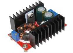
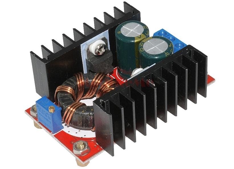
The converter is sold with screwed mounting pins, which is very helpful when mounting it in the target system.
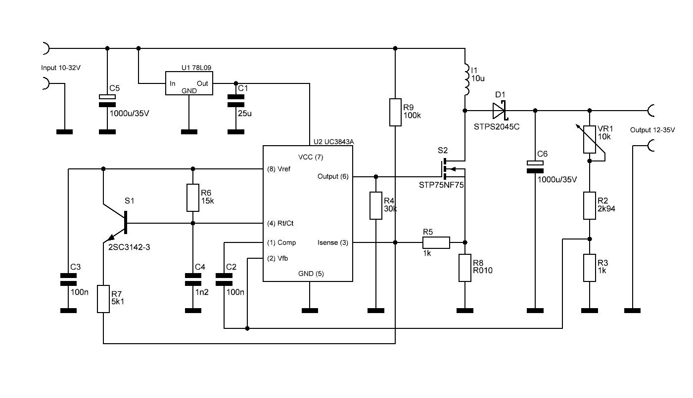
The heart of our tested converter is the UC3843A converter controller. It is powered from the 78L09 voltage stabilizer, so the minimum input voltage of this converter is about 10VDC.
The board also features a choke, a Schottky rectifier diode, a MOSFET transistor, two 1000uF capacitors, a 0.01? resistor used here to measure the current, a potentiometer to adjust the output voltage and a few other small elements.
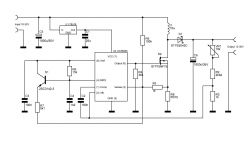
Diagram of the converter below.
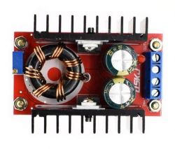
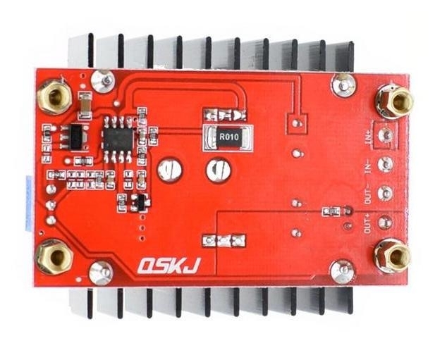
The converter is connected to the power source with cables, by screwing them to the 4-pin KF screw connector, and the output wires to the same connector.
A multi-turn potentiometer is used to regulate the output voltage.
I do not know about other versions of this converter, but in mine there is a 35V capacitor at the output, and the maximum voltage on the converter is also 35V, so it would be appropriate to replace this capacitor if someone intends to use the maximum output voltage.
It's time to start testing.
I powered the converter from a car battery so as not to have problems with power efficiency here.
At the beginning, the measurement of the current consumption in the idle state - it came out about 23mA, so it is within the values declared by the manufacturer.
I set the output voltage to 24VDC.
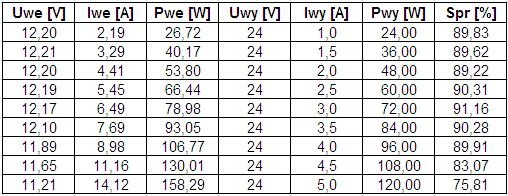
Below is a table with measurements.
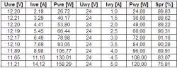
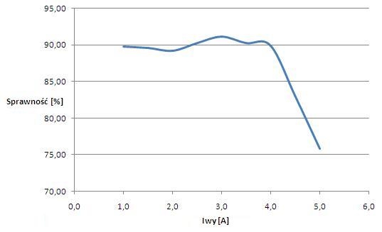
Below is a graph of efficiency to output current.
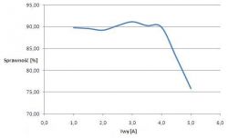
As you can see - here we managed to achieve an efficiency of about 90%, but above 4A (90W) at the output it drops quite drastically.
The temperature of the converter here reached approx. 115 ° C, so you have to be careful not to burn yourself and it is best to provide the converter with a fan. I did not check what temperature the converter could reach. Each measurement here was approx. 40 seconds. I do not know if the converter would survive a longer 120W draw - I did not test it.
After this test, I did one more, where I set the output voltage to the maximum to see how the output voltage behaves. In my case, this voltage was 33.5V.
This voltage was maintained up to about 2.8A, and at about 5A the voltage was less than 21V.
With this test, I did not measure the current consumption from the battery anymore.
During the tests, the converter did not make any squeaks, hums or hums, you can say that you cannot hear its operation.
The inverter was bought for a friend with the intention of using it as a power supply for a laptop in the car and to this day it works. I did not have the opportunity to measure the temperature or the power consumed there, but the converters with this application can be safely held in the hand without fear of burns. It has been in its possession for several months and has not caused any problems to date. It is used up to several hours a week.
Note that this is a step-up converter, so it is not suitable for powering laptops in "TIRs", where there is 24VDC in the cigarette lighter socket.
It should be remembered that this converter has no protections - i.e. there is no protection against reverse power connection, overload and too high temperature.
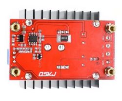
If you want to take more power from it, you should equip it with a fan and you can also think about replacing the heat sinks, because these, as you can see, have something to do with higher powers.
In the descriptions of the sellers you can find information that this inverter can give 100W maximum with natural cooling and a maximum of 150W with forced cooling.
We can also find information that if the ambient temperature is higher than 40 ° C, the converter cooling should be increased.
I have not examined this converter with an oscilloscope, so I will not comment on its "sowing" noise.

Comments
Descriptions in the chart are reversed. I use such a converter and honestly say that with an input voltage of 12V and an output voltage of about 30V, and a power consumption around 35W, after a few hours... [Read more]
MAREK MRK , thanks for vigilance - I have already corrected the descriptions on the chart axes. I am not offended :D I do not mind. [Read more]
The converter asks to remove the heat sinks, solder the transistor and diode on the other side, screw the whole thing to the larger heat sink. In addition, change the choke or stick firmly present and... [Read more]
And could any of you tell me what function the S1 transistor performs in the system? I found no mention of it in the UC3843A datasheet. [Read more]
So I've used it many times to raise the 12v voltage to 15v and power the dipped headlights in many cars. First, the wires are soldered directly to the PCB. Secondly, the converter has voltage stabilization... [Read more]
And is there a drop in the life of the bulbs? Blackened? [Read more]
Nobody has ever bought a light bulb from me for 3 months. I also do not know, I have not checked light bulbs at home yet. [Read more]
Hello, I have been looking for some inverter for some time for my old laptop, which I use from time to time on my car. Small, cool and I have already ordered. We'll see how it works. [Read more]
Seriously? Maybe he didn't buy light bulbs because you burned his whole car? Where did the idea of mounting something like this come from? [Read more]
Just back from Mafia Women, the bulbs are working fine. [Read more]
Raising the voltage of light bulbs in the car. No massacre. The spotlight is probably set off like a table at Durczok's, it's not shining so brightly. https://obrazki.elektroda.pl/74804677... [Read more]
This graph is false because the bulbs are 12V and usually operate at 10-14V depending on the condition of the installation and the car. 15V stabilized is not much more. Previously, I had it done on a... [Read more]
Then calculate as a percentage how much you increase the voltage on the bulb and how it will affect its durability. More precisely, how much will the current increase during switching on where the cold... [Read more]
Ok tomorrow I will measure how much electricity it consumes. [Read more]
What is the resistance of the voltage adjustment potentiometer? 10k?? [Read more]
The diagram and photo show that 10k?. [Read more]
I know that this inverter is not insulated, but is there any similar isolated ground? [Read more]
Well, hardly anyone realizes that in an efficient installation the bulb gets 14.8V and somehow swallows it. Here it will get stabilized 15V and even if you take your foot off the gas, it will not stop... [Read more]
First of all - what is the effect of taking your leg off the throttle if you don't get off the ground first? Secondly - with an efficient car installation, not overloaded with current receivers, you... [Read more]