Hello.
Below I present a description of the step-down converter based on the LM2596S-ADJ chip.
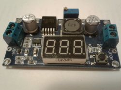
The prices of the converter start on Aliexpress from less than $ 1.60 with shipping, prices with shipping on Polish auction portals start from about PLN 15.
The maximum input voltage for the converter is 35V DC (the converter IC itself can withstand a higher voltage, but the limitation here is the electrolytic capacitor at the input, which here has 35V - you can find converters with a 50V capacitor).
The output voltage is regulated by a potentiometer in the range from 3.2 to 35V DC, efficiency up to about 3A.
Converter dimensions: 65 x 35 x 16 mm
The converter has a built-in voltage measurement circuit on the input and output side, displaying the voltage on a 3-digit display with a resolution of 0.1V. The voltage measurement is switched over using the button. The converter has two LEDs informing about whether the displayed result is a voltage measurement on the input or output side. It is possible to calibrate the voltmeter by holding down the button for a longer time while displaying the value you want to calibrate.
The converter was tested with an artificial load for the input voltages: 12, 15 and 24V and for the output voltages of 12 and 5V.
In the conducted tests, voltages and currents on the input and output side of the converter were measured, power and efficiency were calculated.
Below I present the measurement results.
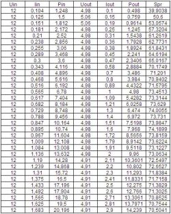
Input voltage 12V, output voltage 5V:
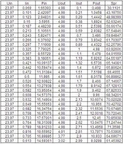
Input voltage 24V, output voltage 5V:
Input voltage 15V, output voltage 12V:
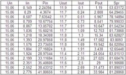
Input voltage 24V, output voltage 12V:
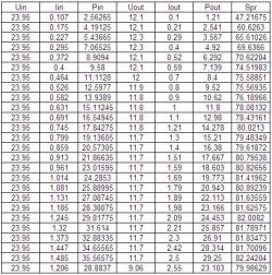
The diagram below shows the efficiency of the converter depending on the current consumed from the converter. We have shown the efficiency for 4 different variants.
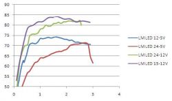
As you can see from the diagram - the efficiency of the converter is not a constant value and it can be seen here that the highest efficiency of the converter is at 15V input voltage and 12V output voltage, and the lowest at 24V input voltage and 5V output voltage.
It can also be seen that the efficiency also varies with the load on the inverter.
As you can see - the efficiency of this converter does not exceed 85%, where many sellers give even greater value in their descriptions.
It can also be seen from the measurements that it is not always possible to load the 3A converter and it will keep the voltage at the output.
I also tested the converter temperature for the configuration where the efficiency was worst - 24V / 5. With a consumption of 2.5A in this configuration, the converter temperature after 30 minutes was about 55 ° C.
Below is a link to the description of a cheaper converter based on the same system, but without a built-in voltmeter.
https://www.elektroda.pl/rtvforum/topic3420289.html#16964655
Below I present a description of the step-down converter based on the LM2596S-ADJ chip.

The prices of the converter start on Aliexpress from less than $ 1.60 with shipping, prices with shipping on Polish auction portals start from about PLN 15.
The maximum input voltage for the converter is 35V DC (the converter IC itself can withstand a higher voltage, but the limitation here is the electrolytic capacitor at the input, which here has 35V - you can find converters with a 50V capacitor).
The output voltage is regulated by a potentiometer in the range from 3.2 to 35V DC, efficiency up to about 3A.
Converter dimensions: 65 x 35 x 16 mm
The converter has a built-in voltage measurement circuit on the input and output side, displaying the voltage on a 3-digit display with a resolution of 0.1V. The voltage measurement is switched over using the button. The converter has two LEDs informing about whether the displayed result is a voltage measurement on the input or output side. It is possible to calibrate the voltmeter by holding down the button for a longer time while displaying the value you want to calibrate.
The converter was tested with an artificial load for the input voltages: 12, 15 and 24V and for the output voltages of 12 and 5V.
In the conducted tests, voltages and currents on the input and output side of the converter were measured, power and efficiency were calculated.
Below I present the measurement results.
Input voltage 12V, output voltage 5V:

Input voltage 24V, output voltage 5V:

Input voltage 15V, output voltage 12V:

Input voltage 24V, output voltage 12V:

The diagram below shows the efficiency of the converter depending on the current consumed from the converter. We have shown the efficiency for 4 different variants.

As you can see from the diagram - the efficiency of the converter is not a constant value and it can be seen here that the highest efficiency of the converter is at 15V input voltage and 12V output voltage, and the lowest at 24V input voltage and 5V output voltage.
It can also be seen that the efficiency also varies with the load on the inverter.
As you can see - the efficiency of this converter does not exceed 85%, where many sellers give even greater value in their descriptions.
It can also be seen from the measurements that it is not always possible to load the 3A converter and it will keep the voltage at the output.
I also tested the converter temperature for the configuration where the efficiency was worst - 24V / 5. With a consumption of 2.5A in this configuration, the converter temperature after 30 minutes was about 55 ° C.
Below is a link to the description of a cheaper converter based on the same system, but without a built-in voltmeter.
https://www.elektroda.pl/rtvforum/topic3420289.html#16964655
Cool? Ranking DIY


