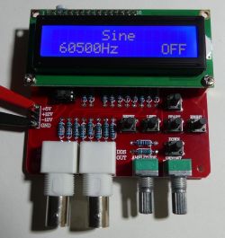
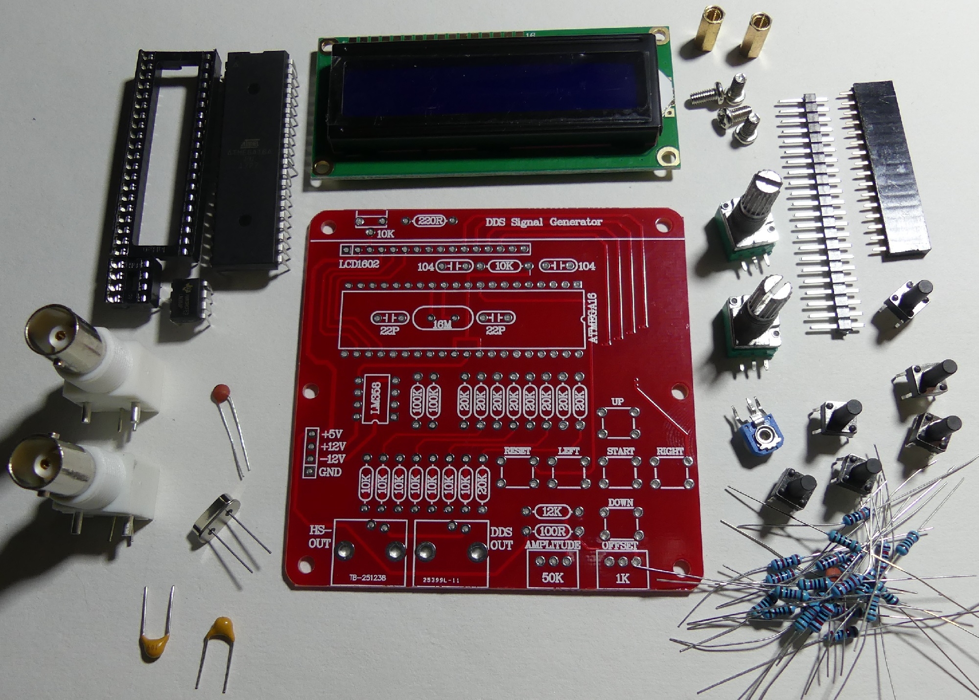
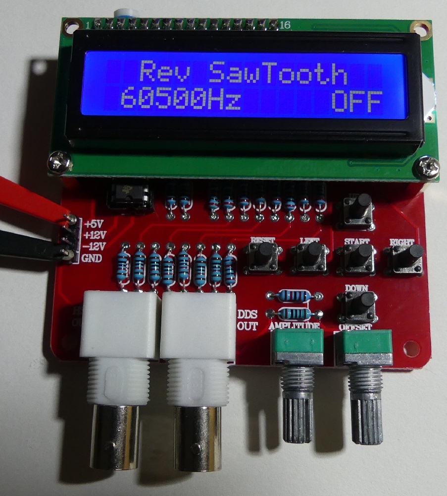
Soon, the DDS generator will appear on elektroda.pl in the form of a mounting kit. The DDS generator allows for the production of 1,2,4,8MHz square signals and signals with a frequency adjustable up to 65KHz, among others with the shapes: sine, rectangle, saw, triangle and noise. The device is equipped with an alphanumeric LCD display with backlight, control buttons and potentiometers for setting the amplitude and constant component of the output signal. Power required + 5V, + 12V, -12V.
It is worth starting the assembly of the device with small elements (resistors, capacitors), through the IC sockets and the LCD connector. The assembly can be done similarly to the mini-scopes
DSO138 . After the + 5V voltage is supplied, the display contrast should be set using the mounting potentiometer.

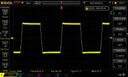
For the operation of the generator of "fast" square waveforms 1,2,4,8MHz it is enough to supply 5V, the HS output will show a square wave signal with an amplitude of ~ 5V. The device consumes ~ 30mA.

For the operation of the DDS generator (Direct Digital Synthesis), a symmetrical + 12V -12V power supply to the output operational amplifier is required. The current consumption in the symmetrical +/- 12V power lines is small (single milliamps), so you can use, for example, a small transformer with a split winding or one-way rectification + 12V stabilizers. You can also use DC / DC inductive or capacitive converters. The 8b DAC converter on the R-2R resistor ladder (10k and 20k) was used to generate the waveforms. Output amplitude adjustable to ~ 18-19Vpp.
Use the buttons to select the waveform and frequency and start the waveform generation. The frequency cannot be changed during waveform generation. Stop signal generation and change frequency.

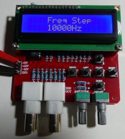
The frequency is changed in steps depending on the settings:
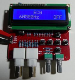
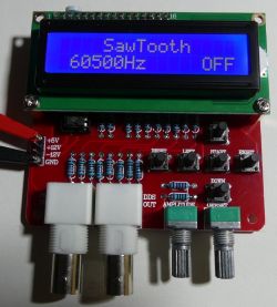
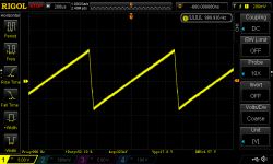
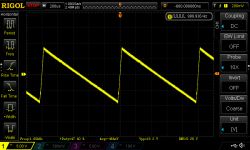
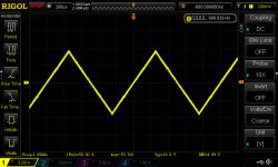
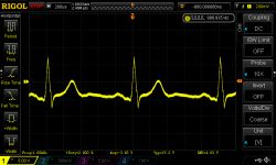
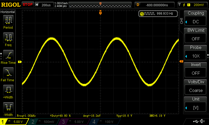
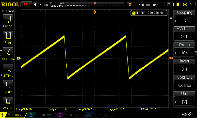
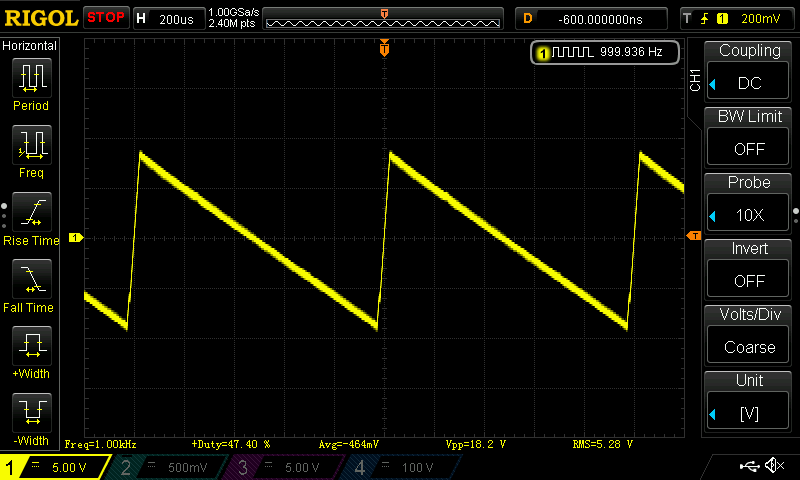
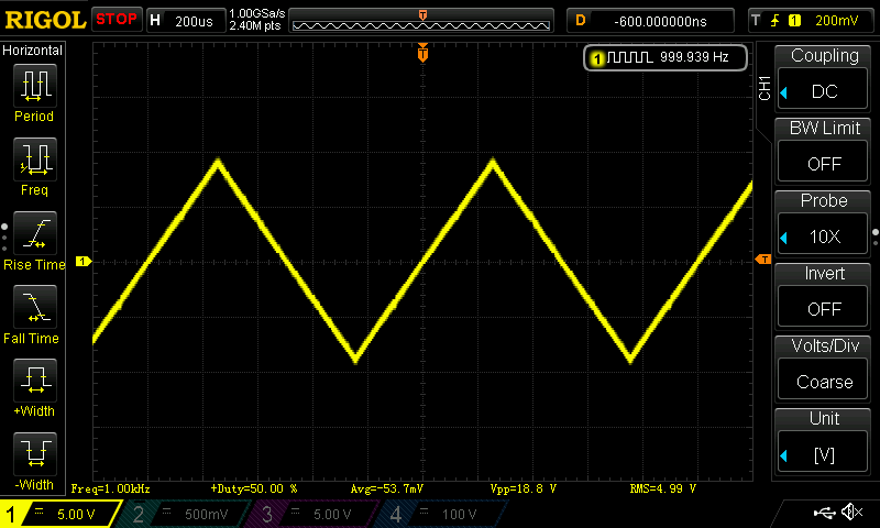
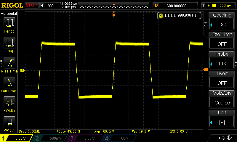
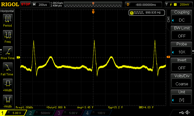
1KHz waveform appearance sine, saw, inverted saw, triangle, rectangle, ECG:
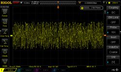
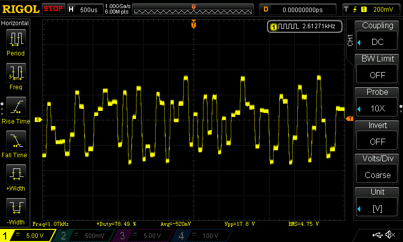
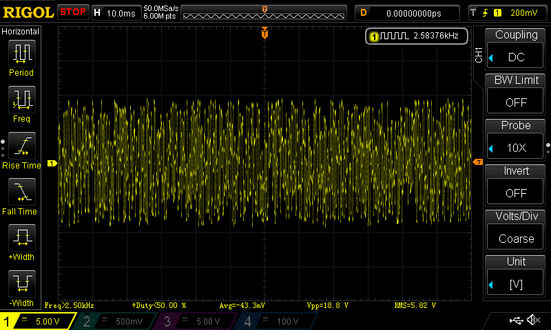
"Noise":
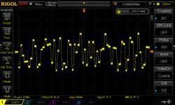
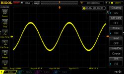
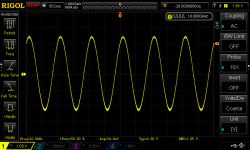
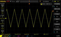
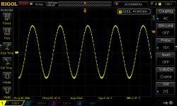
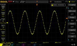
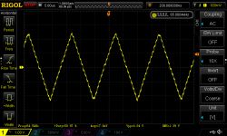
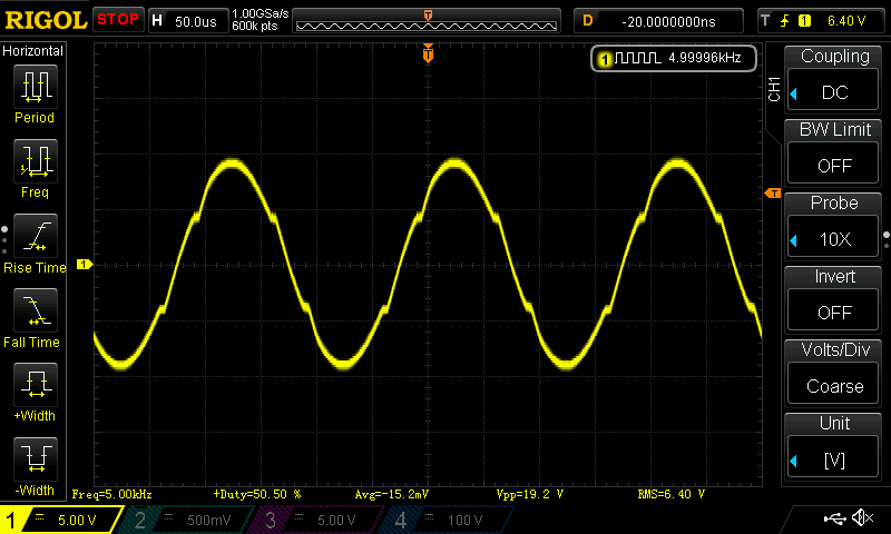
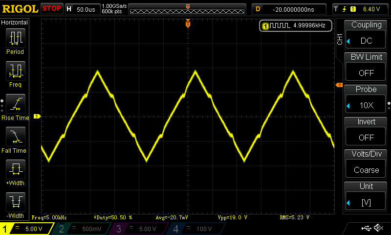
5KHz sine and triangle, you can see the distortion:
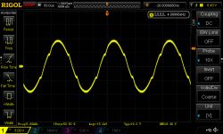
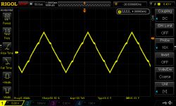
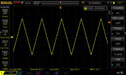
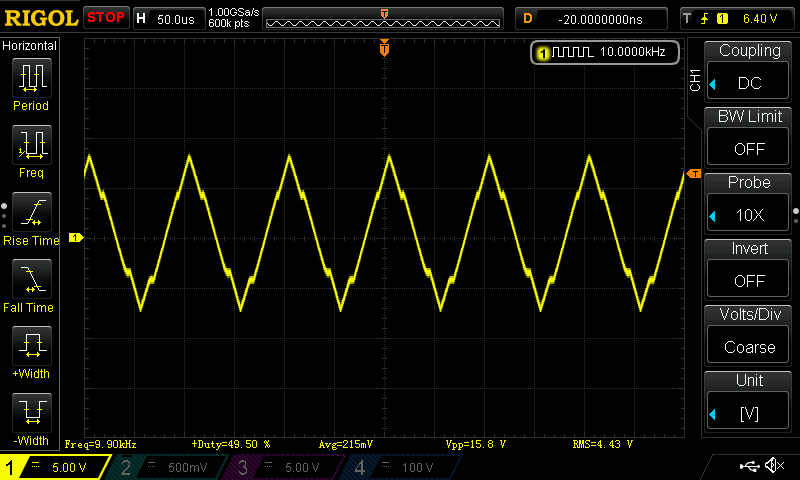
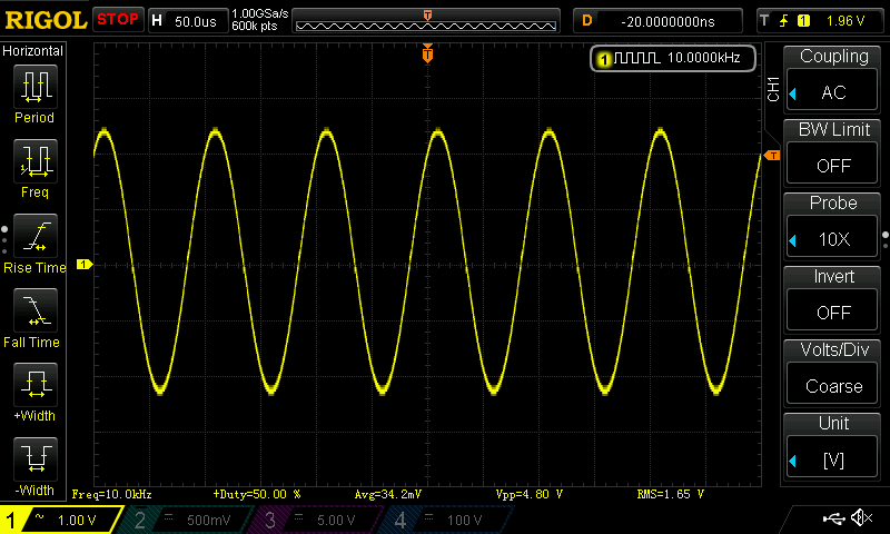
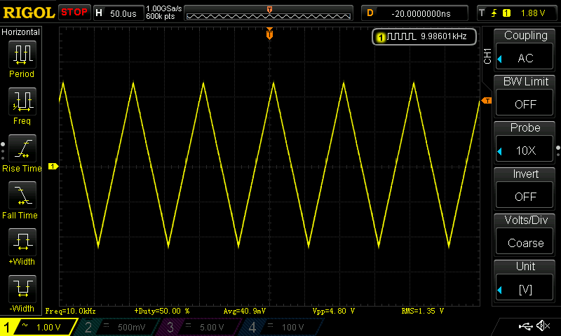
10KHz sine and triangle, the sine is like a triangle:
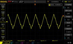
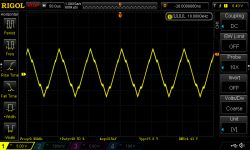
10KHz sine and delta at DAC output, better output amplifier can improve the parameters:
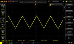
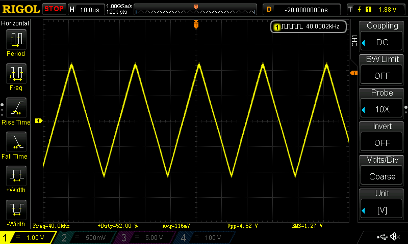
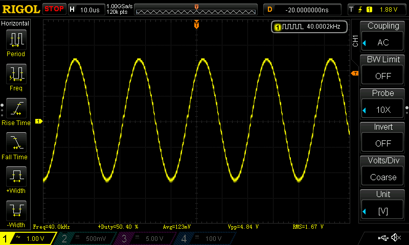
40KHz sine and triangle at the amplifier output and the DAC output:
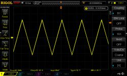
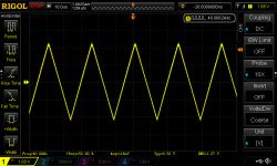
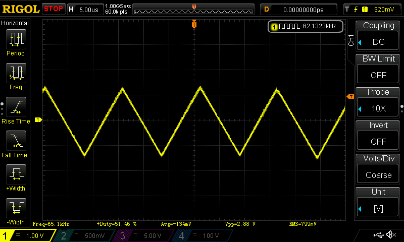
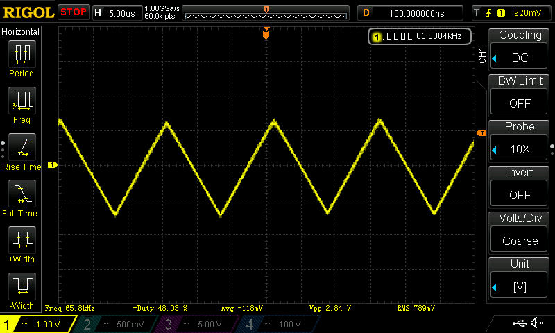
Sine and triangle 65KHz at the output of the amplifier, apart from distortions, you can see changes in amplitude:
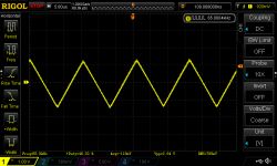
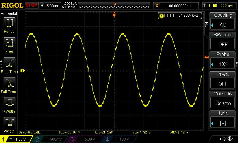
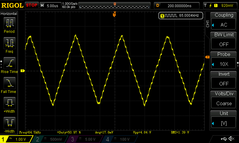
65KHz sine and triangle at the DAC output:
 Do you see an application for this DDS generator, e.g. in audio applications, is it worth modifying the output amplifier circuit?
 Replacing the operational amplifier and improving the parameters of the DDS generator:
https://www.elektroda.pl/rtvforum/topic3445820.html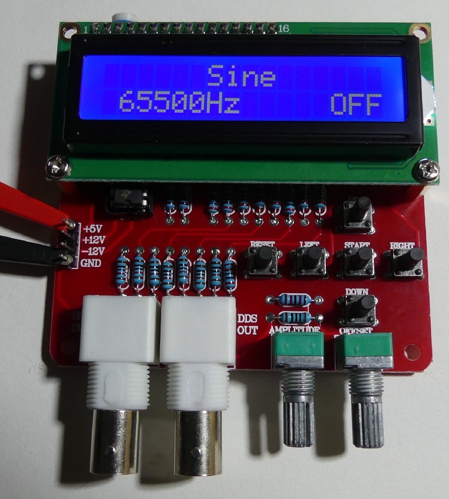


Comments
What is this processor? Maybe it would be worth considering a dedicated DDS chip like AD9851 etc. It is not that expensive, and the quality and possibilities are much greater. [Read more]
No wonder it looks so faint. In my opinion, the lack of a normal DAC disqualifies this circuit. Look, the R-2R ladder uses resistors with a tolerance of 1%. From such resistors, a maximum of 6 bit converter... [Read more]
@ leonow32 prices for ad9850 have gone up terribly lately, I think stocks are running out. The ad9833, on the other hand, is cheap and allows you to directly generate various waveforms. [Read more]
This construction has been hanging on the electronics-lab website for several years. Nothing new. The author of the post copied everything (without giving the source) and slightly modified the appearance... [Read more]
Indeed, the bastards have traveled several times over! But any DAC or a microcontroller with a built-in DAC could be used. The R-2R ladder is for breaking open the door. [Read more]
A few years ago it was made by electronics-lab, although I designed the plates from scratch to have a front panel. The system works, I have it, I use it. [Read more]
The author of the post did not copy. This generator is available on aliexpress and that's where it comes from. [Read more]
Overall useful device. Only this D / A converter on the ladder spoils everything. A D / A like DAC0832 would be a lot better. [Read more]
DAC or ladder with better resistors and perhaps a voltage source would give better results as well as a better amplifier circuit, the microcontroller used is an ATmega16 clocked with a 16MHz quartz. [Read more]
Better performance amplifier and regenerative filter ... [Read more]
I did better: https://www.elektroda.pl/rtvforum/viewtopic.php?p=16745309#16745309 http://avt.4ra.pl/viewforum.php?id=13. There is one more project similar to mine (you have to look for it in competition... [Read more]
What is a regenerative filter? [Read more]
A low-pass filter at the output of the D / A converter, whose task is to filter out the higher frequency components in the spectrum of the reproduced signal. The filter should have a steep slope to ensure... [Read more]
I replaced the LM358 amplifier in the stand with TL082 (I also tested TL072), more information here: https://www.elektroda.pl/rtvforum/topic3445820.html For me, such a trivial upgrade gives very good... [Read more]
or maybe insert something more contemporary? Eg MCP6002 or MCP6022? 100% CMOS, rail is tail and 10MHz will pull, and costs about PLN 5 [Read more]
Everything can be done, I had TL082 on the spot, the effect was very good and sufficient (looking at the capabilities of the tested DDS). For DDS with higher output frequencies, the MCP60XX series can... [Read more]
I noticed in the description that there is a 1Hz jump. What f is it used for? Up to 65kHz? I have the source of this software from 2008. but I can't quite get it out. I mean the possibility of using... [Read more]
@radiosimon in the DDS mode in the range from 0-65535Hz, 1Hz, 10Hz, 100Hz, 1000Hz, 10000Hz steps are available. In HS mode, you can select the frequency of the square wave output as 1MHz, 2MHz, 4MHz,... [Read more]
I guess retuning steps. [Read more]