Today I want to present an interesting (in my opinion) artificial load working in CC mode, in which a test of fast charging modes can be forced from the menu. What is useful for testing chargers and powerbanks with this option. The heart of the device is the MOSFET IRFZ44N. Looking at the parameters of this transistor, the manufacturer conservatively designed the device for 3A and 35W.
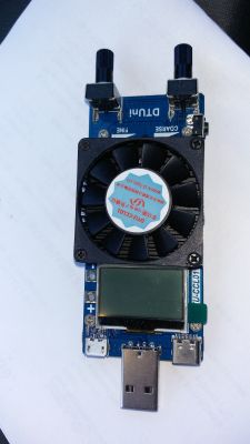
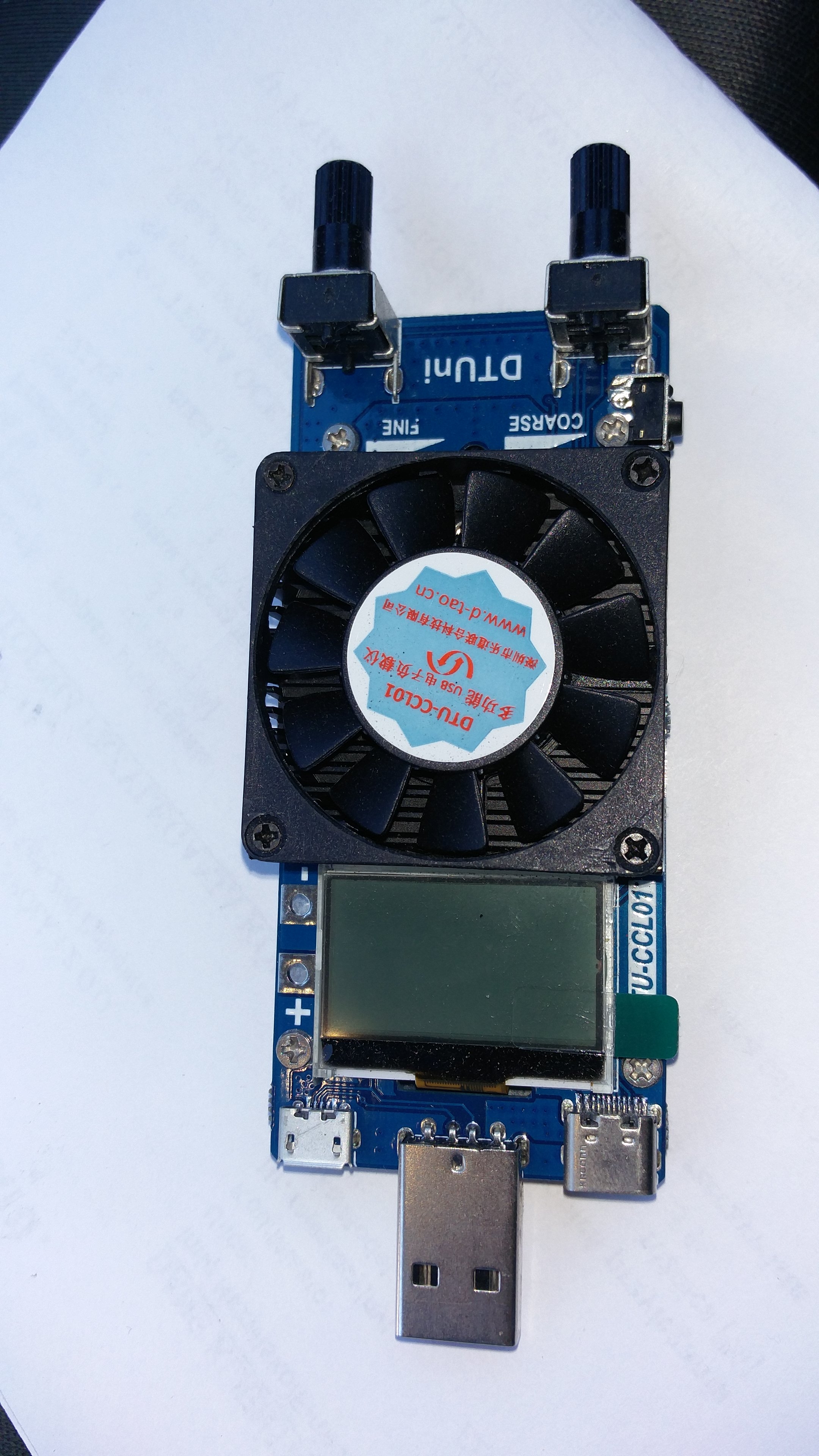
The device looks like this:
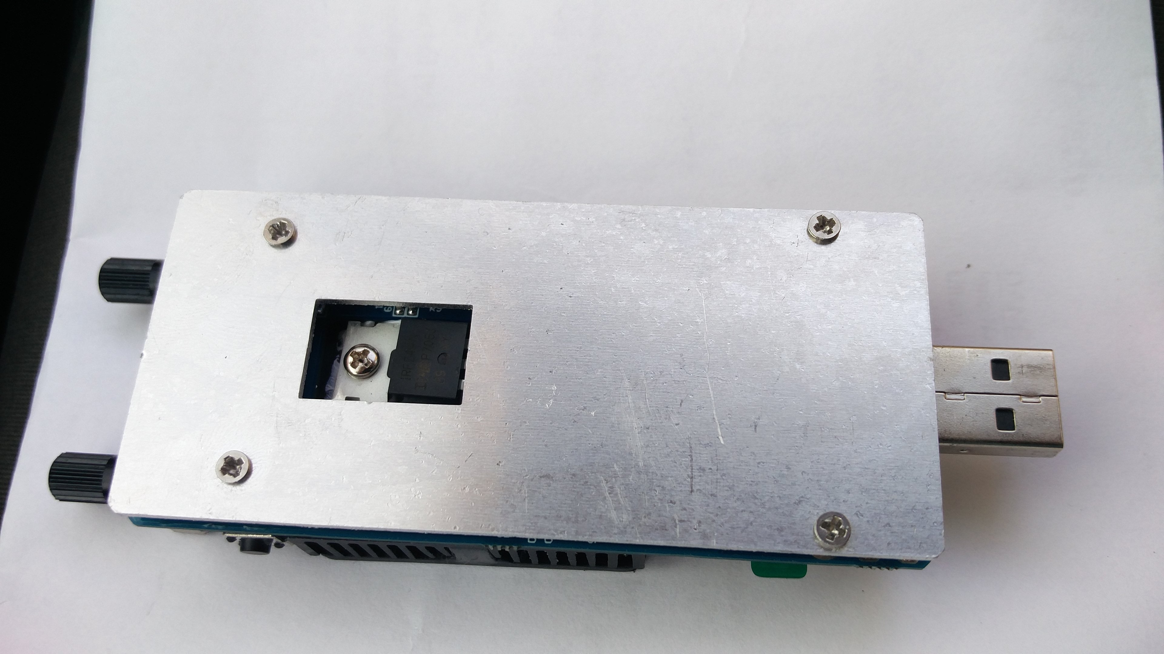
From the bottom like this:
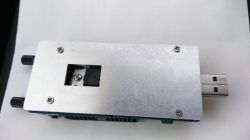
As you can see, the bottom part is a scratched aluminum plate. Hahaha. What aluminum was given there has no idea. In the load I presented earlier.
https://www.elektroda.pl/rtvforum/topic3470459.html Plexiglass cover was much cheaper and easier to process. Which gave a glimpse into the bottom of the device.
At first I thought it was part of the heat sink, but a glance was enough to see that it was just a cover. As you can see, the device has a standard USB connector on the front and microUSB and USB C sockets on the sides. Next we have the display illuminated in white, cold white. So with a blue glow. The display is clear and bright. Next, a small heatsink with a fan. It looks like old, even very old, not very efficient graphics cards.

The fan turns on immediately after supplying power and works non-stop. The fan current consumption is added to the load operation. A takes about 0.2A. There is a repeated symbol of the device on the fan itself. And the manufacturer's website is given. Then there is a microswitch to change the settings and two solidly soldered angle potentiometers. Used to set the load. One exact, the other coarse.
The whole thing looks solidly complex. In my copy, the transistor looks a bit crooked, but it sticks well to the heat sink.
The manufacturer did not regret the paste.
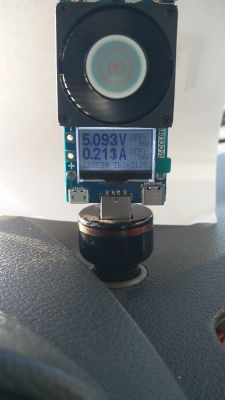
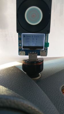
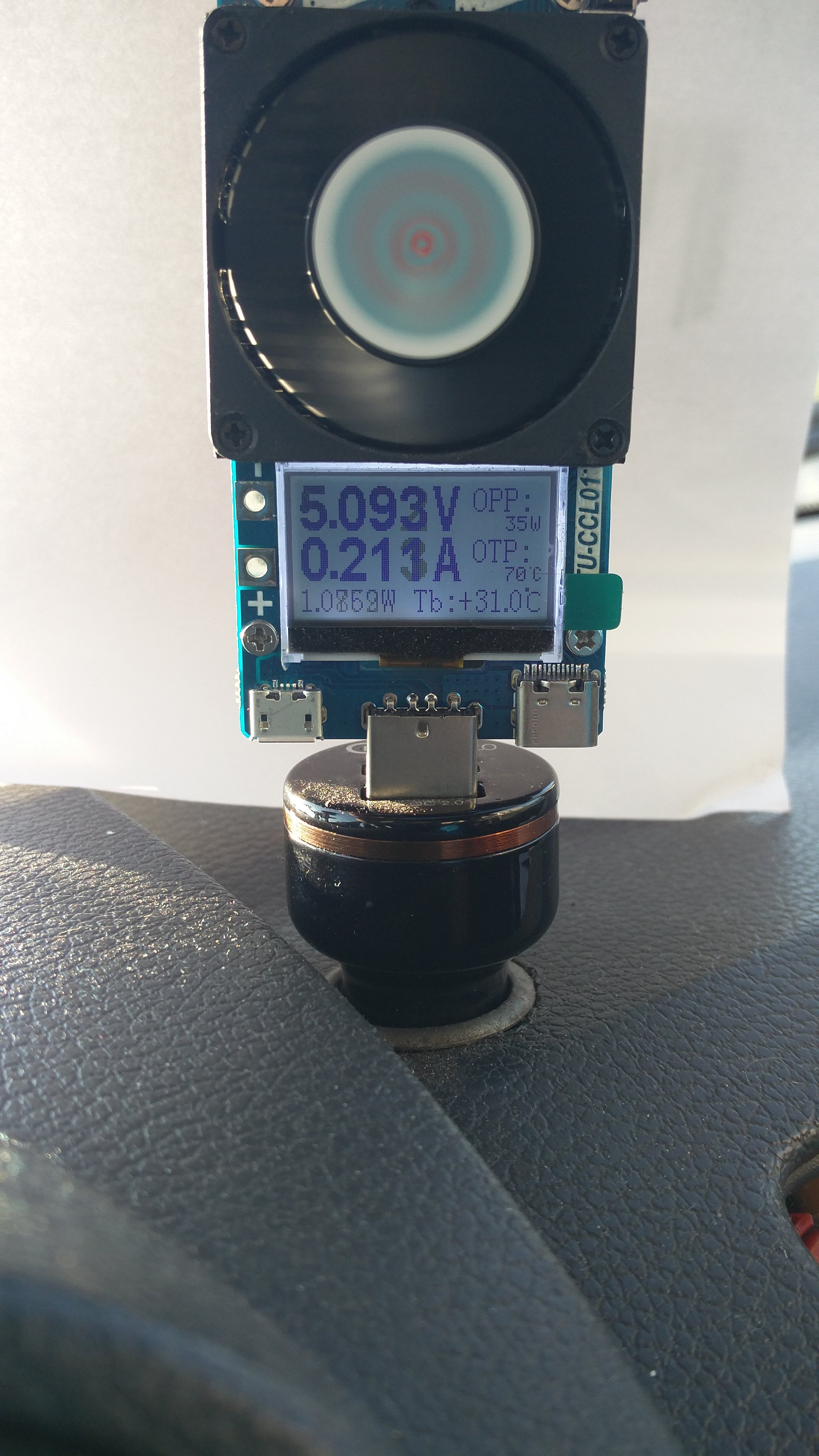
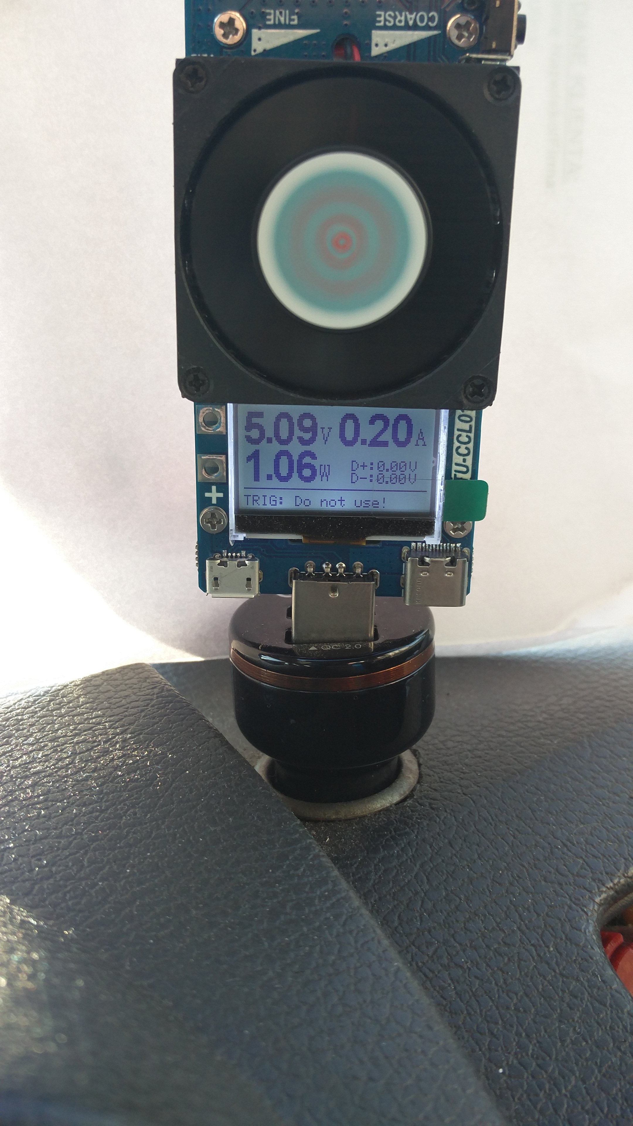
This is what the welcome screen looks like:
After switching on, on the start screen we have information such as voltage and current consumed. As I wrote, the fan is included.
The wattage calculated from this consumption and voltage is shown below. On the right, however, we have OPP markings. This is a preset load limit adjustable in 1W steps from 20W to the currently shown 35W.
And below the OTP with the possibility of setting from 50 ° C to 70 ° C as at the moment. It's a temperature limiter. And at the very bottom, the current temperature, measured near the transistor.
Longer holding of the microswitch causes entering the settings of a given screen. In which we can set the above-mentioned limiters, OPP and OTP as well as rotate the screen indication by 180 °.
Pressing the microswitch shorter always takes us to the next menu screen.

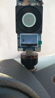
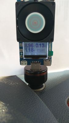
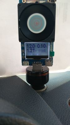
On which, as you can see, we can preview three parameters in large font (two on the previous screen), i.e. voltage, current and power. And the small font for the voltage between the D + and D- signal lines.
Below we can see what fast charging test mode we have set. And this time, after a long press of the microswitch, we enter the next menu in which we have a selection of available fast charging tests. This is what it looks like.
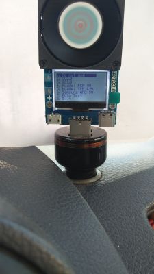
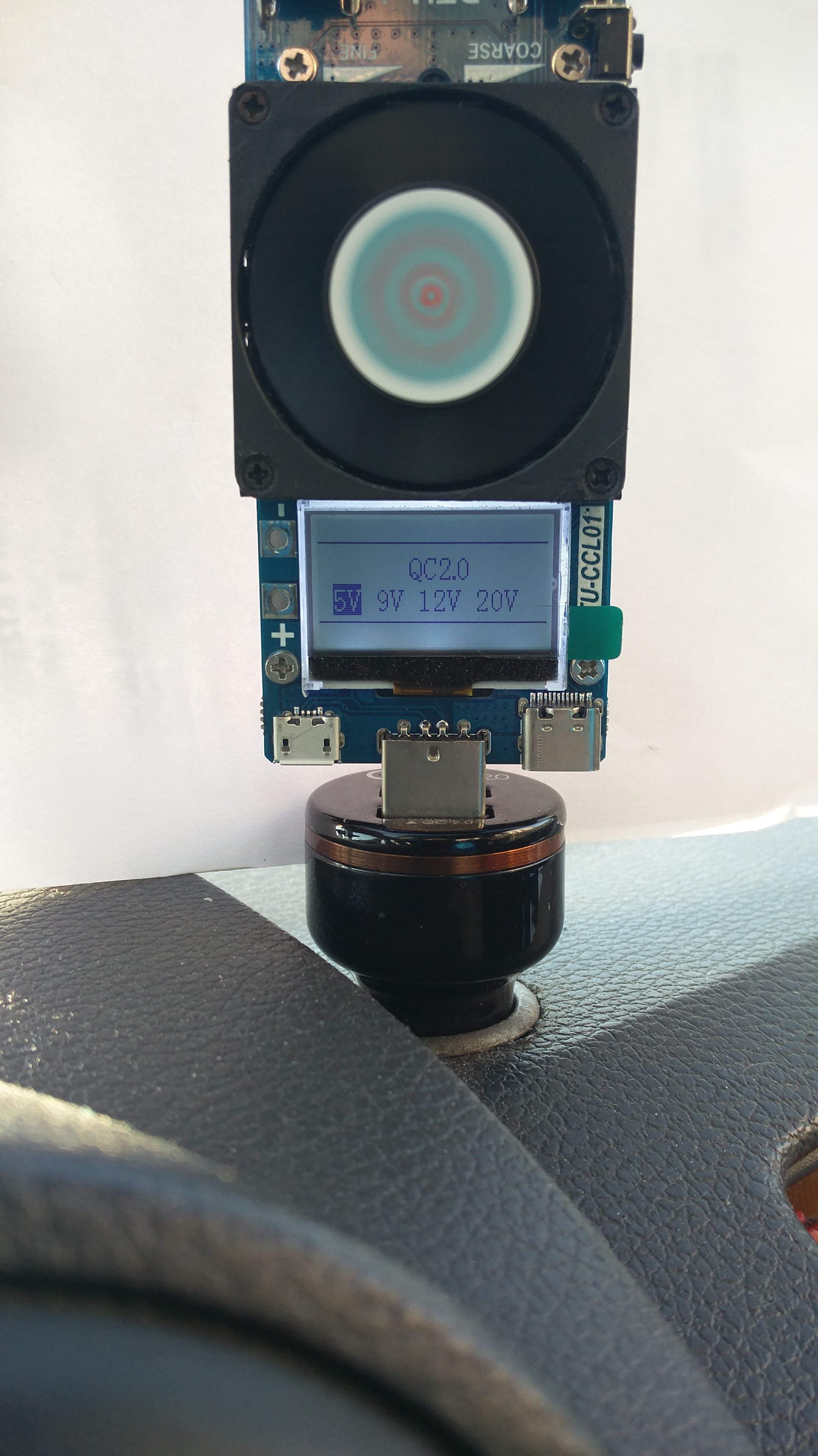
We also have the option of enabling the self-test. Thanks to which, without knowing the possibilities of the charger, we will get the answer what fast charging modes it supports. Since I only have access to the charger in the QC 2.0 standard, I presented what the screen looks like after testing.
Each test takes about 1.5-2 seconds
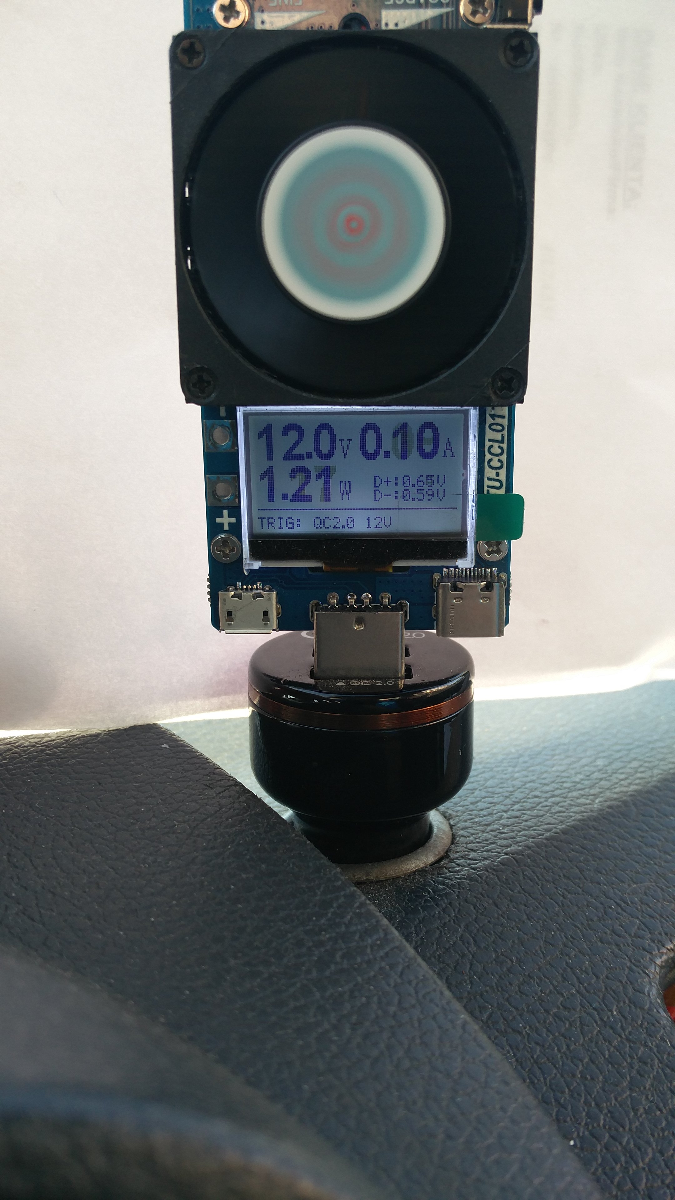
As you can see, the QC 2.0 mode has been detected and the charger itself provides 5V, 9V and 12V voltage.
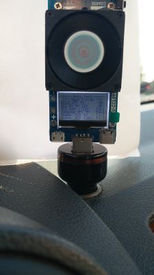
This is the QC 2.0 mode test screen, we can manually select the voltages and test them:
And photos from the tests of individual voltages

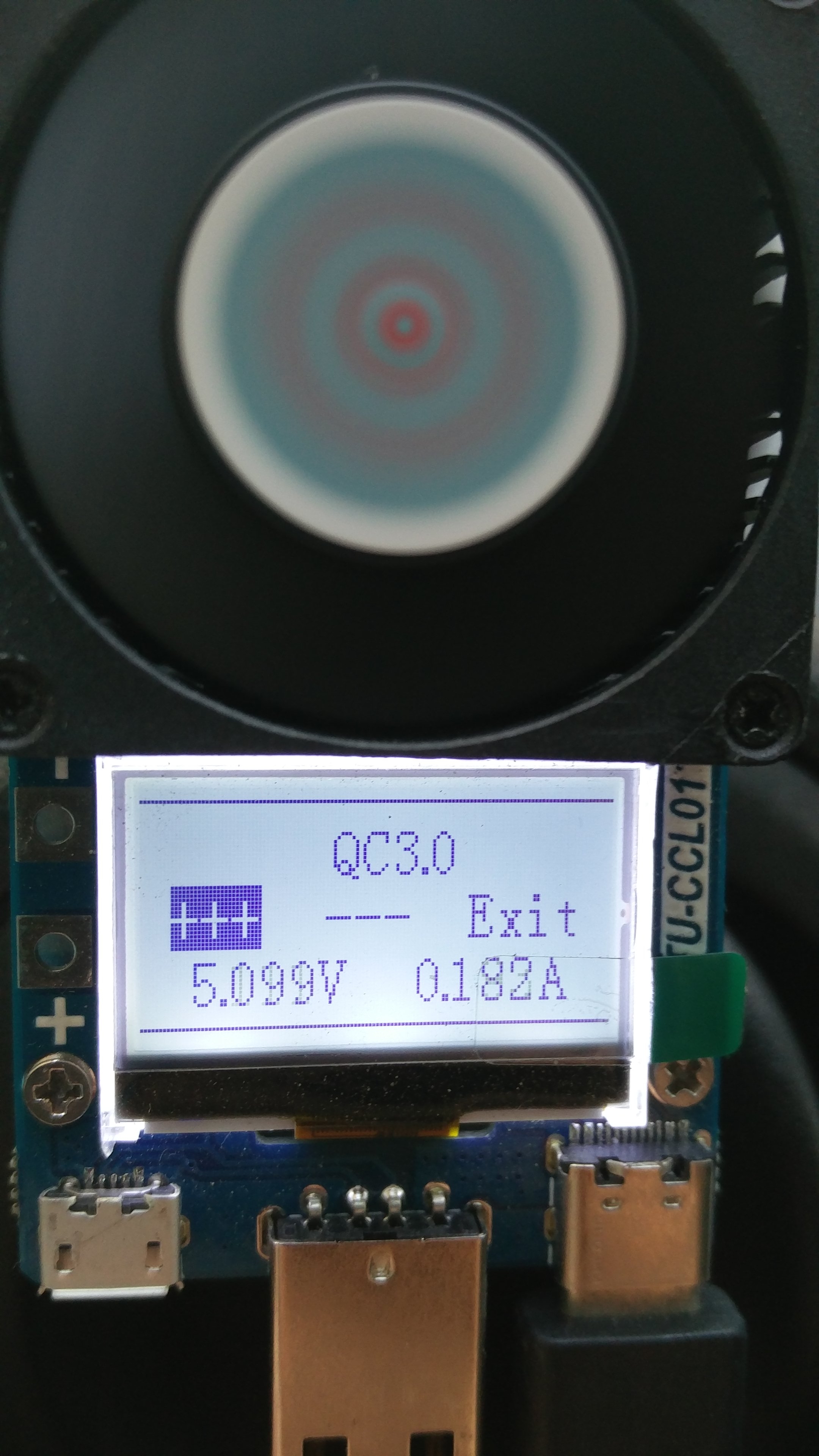
The QC 3.0 mode already has the ability to smoothly adjust the voltage and this is how it looks:
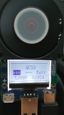
The other modes cannot interfere with the parameters.
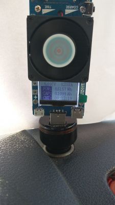
The next menu screen shows the parameters visible in the photo, which can be reset after a longer hold of the microswitch.
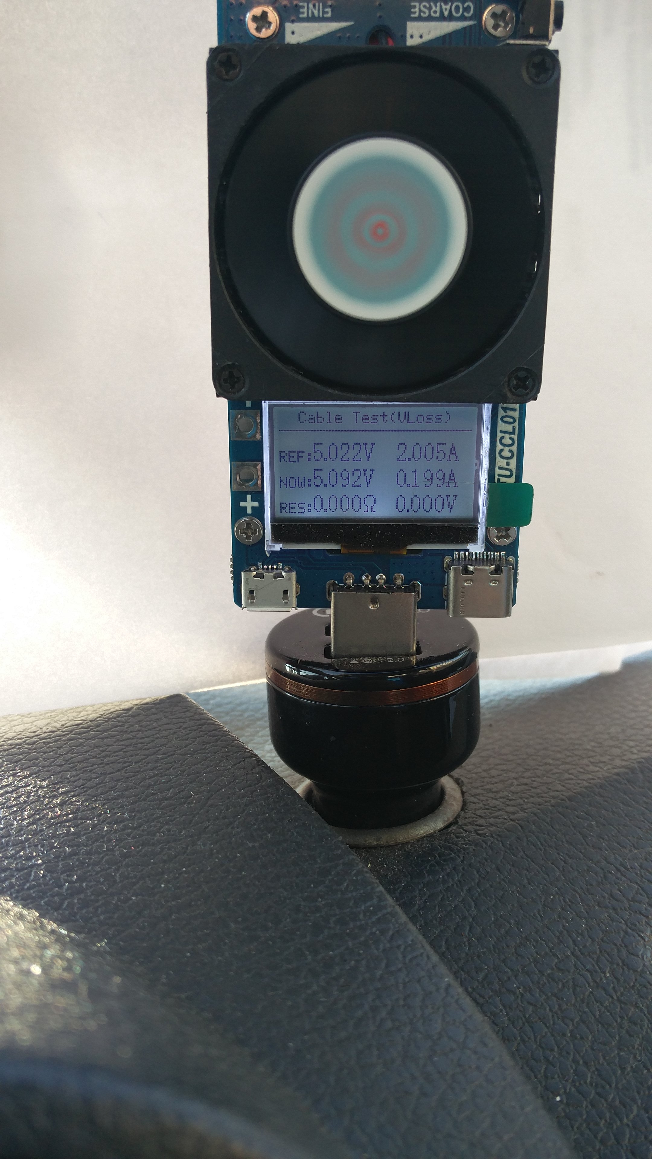
The next menu is the test of connection cables. We set the current value at which we will test the cable, then press and hold the microswitch to remember the reference value. Then remove the tester from the USB socket and connect it via the cable that we want to test and set the earlier value of the current and read the voltage drop and the calculated resistance.

Technical parameters provided by the manufacturer:
Working voltage: 3.6V - 30V
Measured current: 0.2 - 3A.
Display: 128 * 64
Voltage resolution: 0.001v
Current resolution: 0.001A
Rated power: 25w
Max. Power: 35W
Input interfaces: USB-A, TYPE-C, Micro USB
Counted capacity: 0 ~ 9999.9AH, 0 ~ 9999.9Wh
Supported protocols: QC2.0, QC3.0, FCP, SCP, AFC
Measured temperature: 0 - 70 ° C
Size: Approx. 11.5 x 4 x 2.5 cm
Weight: Approx. 57g
I still have to determine the measurement accuracy, which I will do in the near future, for which the terminal marked with + - next to the display is used. And how the security settings that can be set work. The tester came to me on Monday and only today I had a moment for tests and live description. Which took me a while.
Whoever writes knows. :)
Thermal protection I already know how the department. Namely, after the temperature reaches the set threshold, the OTP symbol starts flashing and the load is removed. After the temperature has dropped by 5 ° C, the load is applied again. And the cycle closes.
Same thing with load. After reaching the set threshold, the OPP symbol starts flashing and the load is removed for a moment. Over and over again.
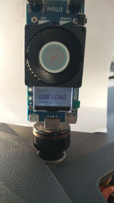
The side contact fields can be used to connect other things in which we want to test, e.g. battery capacity. You can solder the cables there or screw them with screws. You can now use the crocodile clips. Or to permanently solder a stylish twisted field or to a spring. Full freedom.

So all kinds of batteries and accumulators that we want to test can be connected there. You just have to remember about the voltage of the device. We cannot connect an external power supply here. The device works on 3V, unfortunately it no longer measures the voltage properly below 3.1V. Electricity and power are applied correctly. Below 2.5V the fan slows down significantly, the display fades. The device itself stops working at about 2.1V, so lithium cells for testing. You just have to remember that there are no voltage limiters and you have to keep an eye on the minimum voltage yourself. So as not to beat the link.
During the tests, I noticed an interesting flaw in the control system. Namely, after setting the load to 1A at 5V, this setting was kept up to 18V. It is known that the power dissipated increased with increasing voltage. But when this voltage was exceeded, the load was reduced. And at 20V it was only 0.38A. At 30V it is 10 times less. So when the voltage is high and the current of the saucer is not at all high, we have a surprise when the cells are discharged in the form of exceeding the permissible power.
What's more, with a voltage of 30V I managed to get a little over 1A and 32W of power. The potentiometers did not allow for more. However, with lower voltage, including the fan, I got 3.35A
When working with a maximum power of 35W, the built-in thermometer shows a rapidly increasing temperature of up to 70 ° C, while at 30W we have about 60 ° C
What else I noticed that as the temperature rises above 23 ° C, the fan speed increases. They also grow above 18W.
In summary, it is a successful design, especially for those who want to check whether the newly acquired charger supports the declared operating modes. So we can tell why our phone, tablet, etc. is charged so slowly, has its drawbacks, but what is not.
Device bought on AliExpress. It cost about PLN 65.


Comments
Thank you for the description, but the spelling .... With ali. correct please. [Read more]
@kkknc , can you confirm that in this version of the device there is no option to use it only for measurement? Ie. I cannot connect another load (e.g. a telephone) and take measurements? So compared... [Read more]
Exactly this device is not through-going. So you can test the capacity and load of the power bank. And the parameters of the charger. It is impossible to check how much energy goes to the battery of... [Read more]
Don't worry about mistakes. You will get used to them over time. [Read more]