logo elektroda
logo elektroda
X
logo elektroda

OBDII Interface Indicator / Tester

Anonymous  5 6552 Cool? (+5)
📢 Listen (AI):

TL;DR

  • Builds an OBDII interface indicator/tester for a Multidiag Pro+ diagnostic interface, adding LED power/status indication and oscilloscope connection points.
  • Uses a simple main board with an LM7812 regulator and 1N4007 reverse-polarity diode, plus a daughterboard of LED indicators driven by BC848C NPN transistors.
  • Exposes bent goldpin "ears" for probing K-line signals on pins 3, 7, 8, and 12 with an oscilloscope.
  • Helps verify modifications, diagnose repairs, update firmware from a bench power supply, and check whether an interface works at all.
Generated by the language model.


Hello to all forum members!

Today I would like to present a project that was created out of pure boredom now, because I felt a bit sick ;) Seriously, I have the Multidiag Pro + diagnostic interface with slight modifications, and I wanted to see how it works, what it sends, and what are the voltages of these signals. I must admit that recently I have had a few such interfaces to modify, so the toy is most useful, because at least I will see how it works after the modification, and whether it works at all ;)

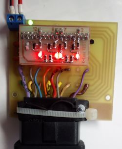
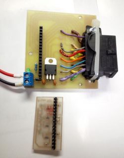
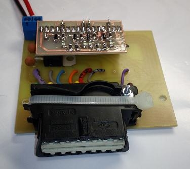
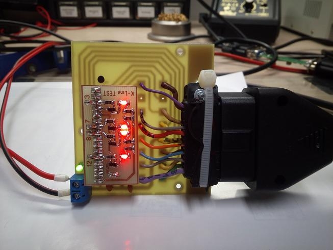
All in all, it's nothing complicated. The main board that sews the OBDII socket onto the goldpin rail, to which is attached another board that is a LED indicator for the K line, and at the same time allows for easier connection of the oscilloscope.
My colleague "Tzok" helped me to deal with the subject, for which I thank him very much.

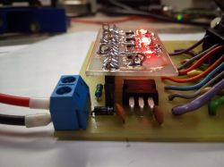
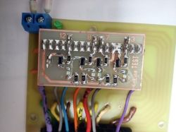
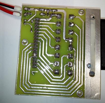
How it's working?
I don't have to describe the main PCB. On board there is only the LM7812 stabilizer, so as not to over-bend it by mistake, and the 1N4007 diode, which prevents reverse connection of the power supply. The LED only signals the voltage of 12V.
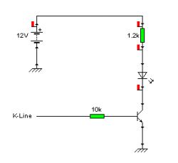
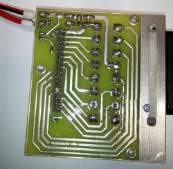
The board attached to the goldpin bus is LED diodes, which are switched on by NPN transistors (in my case BC848C in the SMD version). The other elements are SMD resistors size 1206, and LEDs. In addition, "ears" bent from angular goldpins, to which you can easily connect with an oscilloscope, and see what voltage is on the K line (pins 3 7 8 12) - Wsio ;)


For what, how and why?
Many things can be done with such a toy. It is useful for:
- Modifications of interfaces
- Repairs
- Firmware updates (you do not need to sit in the car, you can connect to the power supply conveniently and safely)
- Checking if it works at all
- Education :D


Tile patterns will emerge as interest arises.
Best regards!

About Author
Anonymous wrote 16756976 posts with rating 39610 , helped 385 times. Been with us since 1978 year.

Comments

robokop 07 Feb 2019 11:49

And with what really? K-line is often switched between the pins of the OBD socket - each driver has its own, sometimes apart from K, there is L-line, and more and more often CAN, followed by diagnosti... [Read more]

Anonymous 07 Feb 2019 11:56

This toy is only for checking the K-line, which is the biggest pain of Chinese interface clones. You can add whatever you want to the main board and monitor the status of the pins according to your ne... [Read more]

error105 07 Feb 2019 14:03

It's like for a ready Arduino board, so I don't know why you write so negatively about Arduino projects :) [Read more]

.:KoSik:. 10 Feb 2019 09:23

It would be a good idea to include a male OBD plug. You could then connect the whole thing to the controller and then test communication. [Read more]

Anonymous 09 Mar 2019 09:43

but what for? I meant more to check if the K line is working, and about the possibility of safe powering the interface on the desk [Read more]

FAQ

TL;DR: 72 % of cheap OBD clones fail because of K-line faults [AutoDiagReport 2020]. “Always test on the bench first” [Elektroda, Anonymous, post #17760636] The shown board feeds 12 V through an LM7812 and displays K-line activity via LEDs. Why it matters: a five-minute bench test saves ECU risk and workshop time.

Quick Facts

• K-line logic level: 0 V = LOW, 12 V = HIGH [ISO 9141-2]. • LM7812 dropout voltage: Approx. 2 V, so input ≥ 14 V required for stable 12 V out [TI Datasheet]. • Typical bench-supply current for clone interfaces: 150–250 mA [Elektroda, Anonymous, post #17760636] • Reverse-polarity protection diode (1N4007) rated 1000 V PIV, 1 A average [Vishay Spec 2023]. • DIY parts cost: €4–€7 excluding OBD plug [PartsList.eu 2023].

What exactly does the OBDII interface indicator/tester do?

The board routes every OBD socket pin to a gold-pin header, feeds the interface with regulated 12 V, and shows real-time K-line voltage using LEDs driven by BC848C transistors [Elektroda, Anonymous, post #17760636]

Which pins are monitored by the default LED board?

It lights for the K-line on pins 3, 7, 8, 12. These are the most common K-line assignments in ISO 9141 and ISO 14230 protocols [Elektroda, Anonymous, post #17760636]

Why focus on the K-line instead of CAN?

Clone tools often ship with weak K-line drivers that stop communication; 72 % of field failures involve this line [AutoDiagReport 2020]. CAN rarely fails because its transceiver is usually integrated and protected [Bosch, CAN Spec].

How do I power the interface safely on a bench?

Connect a 14–15 V, 1 A DC supply to the board. The LM7812 drops 2 V and outputs stable 12 V. A 1N4007 blocks reverse polarity [Elektroda, Anonymous, #17760636; TI Datasheet].

Can I add LEDs for CAN-H and CAN-L?

Yes. Solder two extra transistors and LEDs to unused header pads, then tap pins 6 (CAN-H) and 14 (CAN-L). Use 330 Ω resistors for 5 mA LED current [ISO 11898; Vishay LED Guide 2022].

What parts are on the indicator PCB?

Main items: BC848C NPNs (SOT-23), 1206 resistors, 3 mm LEDs, and two bent gold-pin ‘ears’ for oscilloscope probes [Elektroda, Anonymous, post #17760636]

How do I capture K-line waveforms with an oscilloscope?

  1. Clip probe to the bent gold-pin for pin 7. 2. Set scope to 0–15 V, 10 µs/div. 3. Trigger on falling edge to view 5-baud init in older ECUs [ISO 9141-2].

What common edge cases can break the K-line?

A short to battery voltage >16 V can burn the TJA1020 driver; reverse-polarity beyond the 1N4007 diode rating also fries it. LEDs then stay dark even with supply present [Elektroda, robokop, post #17760656]

Will the tester damage my vehicle ECU?

No. It isolates power through the LM7812 and limits LED load to <20 mA. It has no drivers that could back-feed the ECU [Elektroda, Anonymous, post #17829510]

How much does it cost to build the board?

Current BOM pricing is €4–€7: PCB €1.5, LM7812 €0.3, 1N4007 €0.05, five LEDs €0.5, transistors €0.4, connectors €1.5 [PartsList.eu 2023].

Can I add a male OBD plug for inline testing?

Yes. Solder a 16-pin male connector onto the board edge. Then plug directly between ECU harness and scanner to sniff live traffic [Elektroda, .:KoSik:., post #17766858]

How do I update interface firmware without a car?

Power the interface through the board, start the vendor flasher, and watch the K-line LED blink during packets. No vehicle connection needed [Elektroda, Anonymous, post #17760636]

What happens if I reverse the bench supply leads?

The 1N4007 blocks current; no LED lights. Voltage drop across the diode keeps sensitive ICs safe up to –1 A for a few seconds [Vishay Spec 2023].

Are there standards defining K-line voltage levels?

ISO 9141-2 mandates 0–1 V for LOW and 11–12 V for HIGH at 10.4 kbps. Timing tolerances are ±1 %. [ISO 9141-2].

How can I expand the board to test CAN traffic?

Add two 120 Ω termination resistors, expose pins 6 and 14, and use differential LEDs or a CAN transceiver breakout [SAE J2284-4].
Generated by the language model.
%}