Hello to all forum members!
Today I would like to present a project that was created out of pure boredom now, because I felt a bit sick
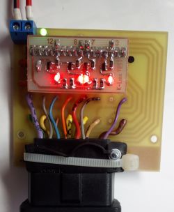
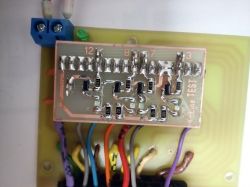
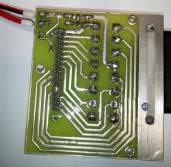
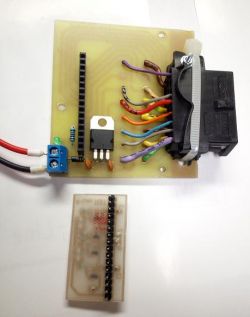
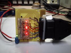
All in all, it's nothing complicated. The main board that sews the OBDII socket onto the goldpin rail, to which is attached another board that is a LED indicator for the K line, and at the same time allows for easier connection of the oscilloscope.
My colleague "Tzok" helped me to deal with the subject, for which I thank him very much.
How it's working?
I don't have to describe the main PCB. On board there is only the LM7812 stabilizer, so as not to over-bend it by mistake, and the 1N4007 diode, which prevents reverse connection of the power supply. The LED only signals the voltage of 12V.
The board attached to the goldpin bus is LED diodes, which are switched on by NPN transistors (in my case BC848C in the SMD version). The other elements are SMD resistors size 1206, and LEDs. In addition, "ears" bent from angular goldpins, to which you can easily connect with an oscilloscope, and see what voltage is on the K line (pins 3 7 8 12) - Wsio ;)
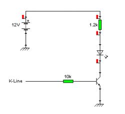
For what, how and why?
Many things can be done with such a toy. It is useful for:
- Modifications of interfaces
- Repairs
- Firmware updates (you do not need to sit in the car, you can connect to the power supply conveniently and safely)
- Checking if it works at all
- Education :D
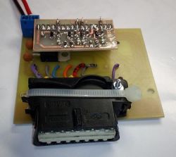
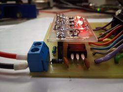
Tile patterns will emerge as interest arises.
Best regards!


