Hello everyone
Today I would like to introduce you to the design of a tube amplifier, this is my second tube design. After the successful construction of a long wave tube radio receiver - link below
https://www.elektroda.pl/rtvforum/topic3549270.html I decided to build a tube amplifier - as the budget for a tube amplifier was not too big, I decided to use what I had at hand, i.e. components from old Bambino turntables and ZK120 and ZK140 tape recorders.
My assumption was to build a low-power stereo amplifier with a drive indicator. The circuit includes two ECL86 tubes and two EM84 magic eye tubes, for this I used two Bambino output transformers and two mains transformers. I decided to make two separate monoblocks, i.e. completely separate mono amplifiers in one housing.
I decided to make a PCB for the amplifier - just like before, I decided to make a PCB design in Eagle, and then improve the track layout in GIMP so that the PCB looks like the one from the AM radio to which I gave the link above.
As I had not done a tube project using high anode voltages before, after thinking about it, I prepared a few PCBs:
- Two mono amplifier PCBs
- Two PCBs for the control indicator
- Anode voltage switching delay board (ready-made board design)
- Audio input selector board (not designed yet)
- Two anode voltage stabilizer plates (not designed yet)
- Phono preamplifier board (ready-made board design)
On the amplifier board, I designed a high-voltage rectifier bridge, because so far the original selenium rectifier is used (one per channel) and an electrolytic capacitor from Bambino (I plan to put only lamps without transformers on the housing and this electrolytic capacitor - actually two capacitors in one housing). However, transformers will be built in due to the high voltage present on them - therefore for safety reasons.
It is true that the design of the amplifier itself is already started and the only thing left to do is make a housing for it - I will do it in spring or summer, depending on the weather (outside temperature). I plan to make the housing of wood, but I haven't thought about the details yet.
Below I present photos of PCBs
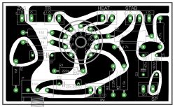
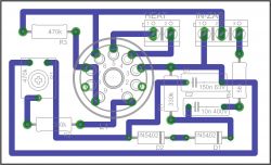
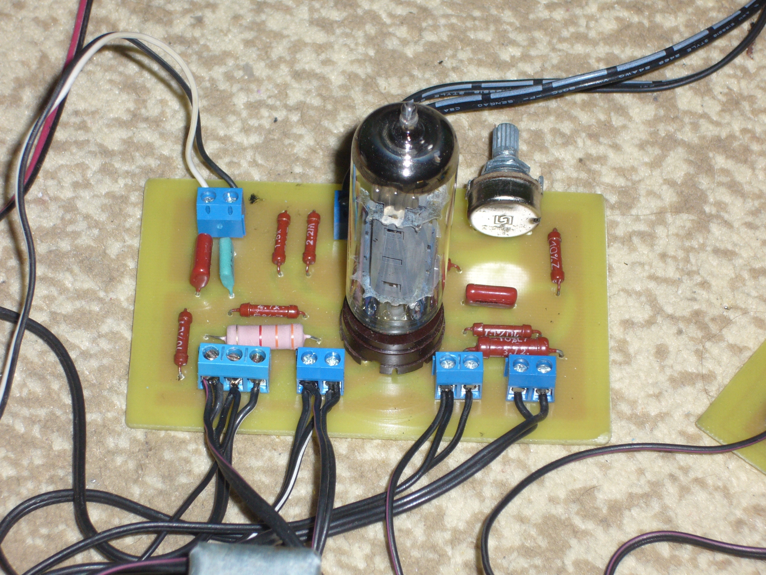
The first board is the ECL86 amplifier. Description of the pins of the board:
- ZAS - power supply - here we connect the power supply directly from the selenium rectifier + high power supply is on the left in the graphic and - on the right.
- TR - loudspeaker transformer - connect the primary winding as shown in the diagram (it will be below)
- HEAT - lamp incandescence - connect alternating voltage directly from the 6.3V mains transformer
- STAB - the output to which the electrolytic capacitor is currently connected to the housing - connect in such a way that the outermost outputs go to the two pluses of the capacitor and the middle one is a minus, i.e. the capacitor housing (electrolytic capacitor used in turntablesThe Bambino has two capacitors in its housing, hence three outputs - two pluses and a minus on the housing). In the future, this screw connector will be used for a possible expansion of the amplifier with an anode voltage stabilizer, then the voltage stabilizer will be connected, looking at the graphic, from the right there will be the middle ground input and the left stabilized voltage output. When using such a stabilizer, it will be necessary to remove the 3.3k resistor - R9.
- SP - i.e. speaker connection - connect the speaker there as well as the secondary winding of the speaker transformer.
- IN - mono input of the amplifier.
- P - potentiometer for volume control. Ultimately, it will be replaced by a jumper, and the audio signal directly from the chinch inputs will go to the stereo potentiometer, and then to the mono amplifier inputs (the mono potentiometer on the board will be replaced by a jumper)
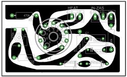
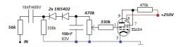
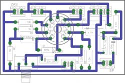
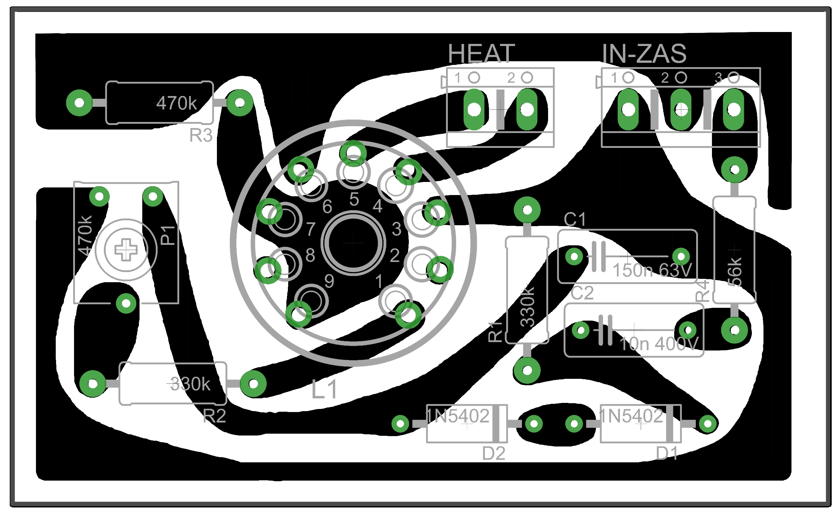
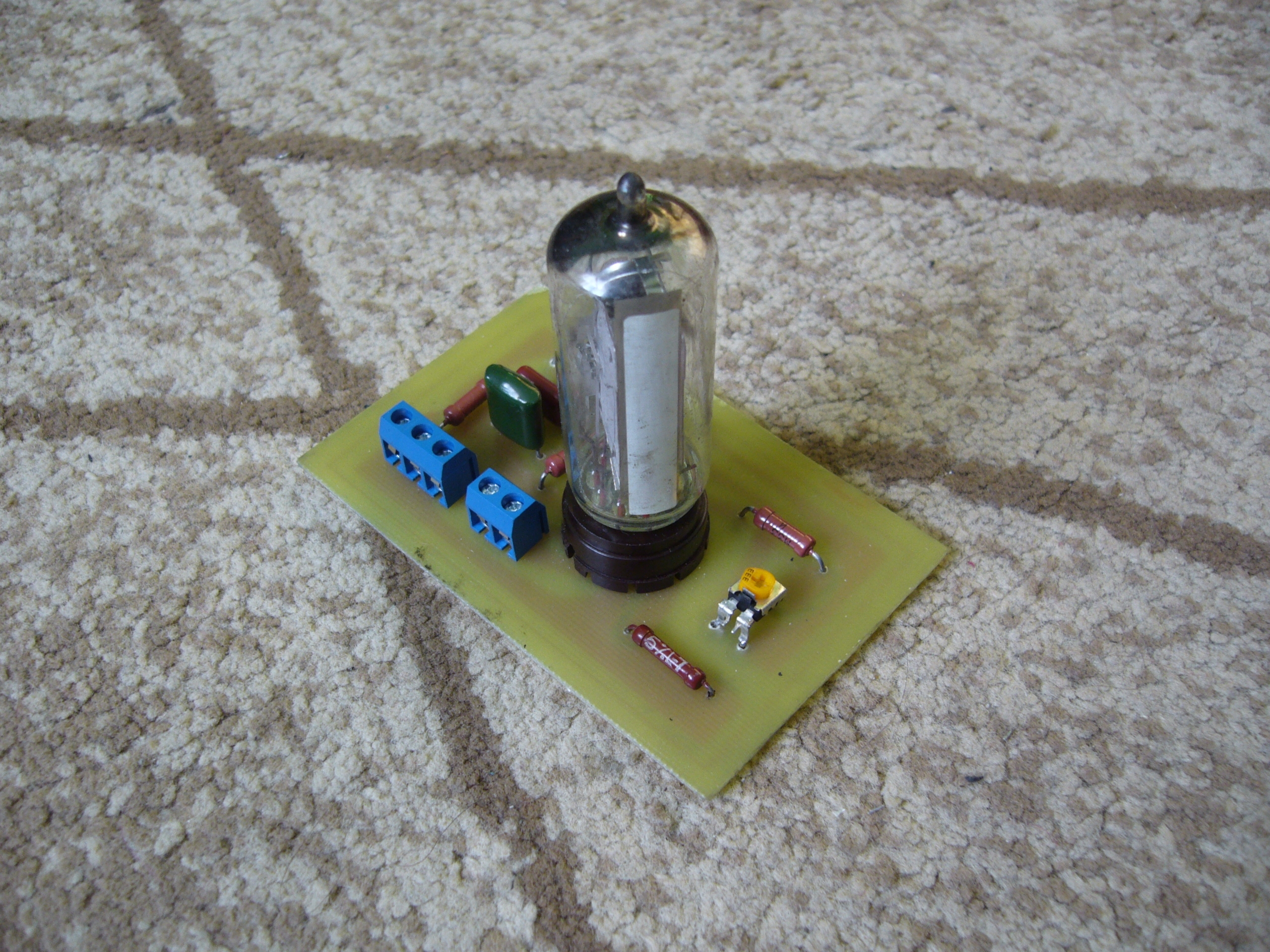
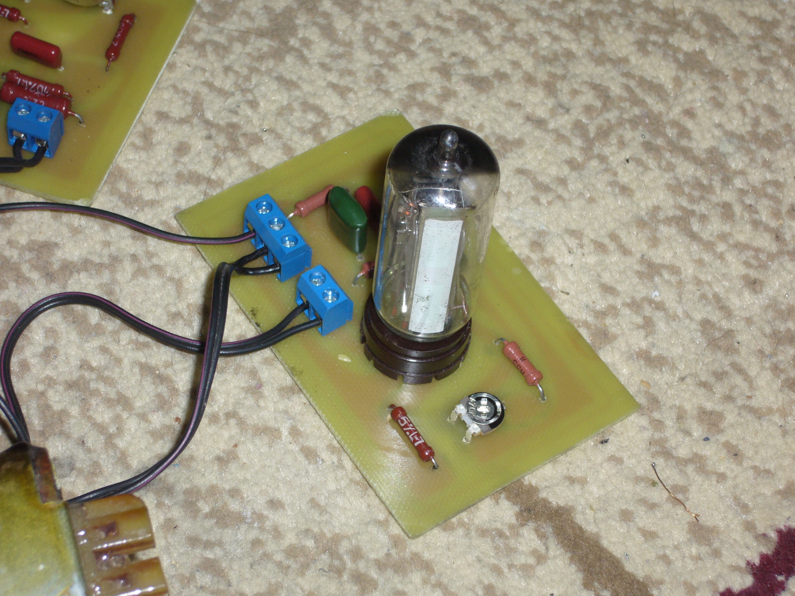
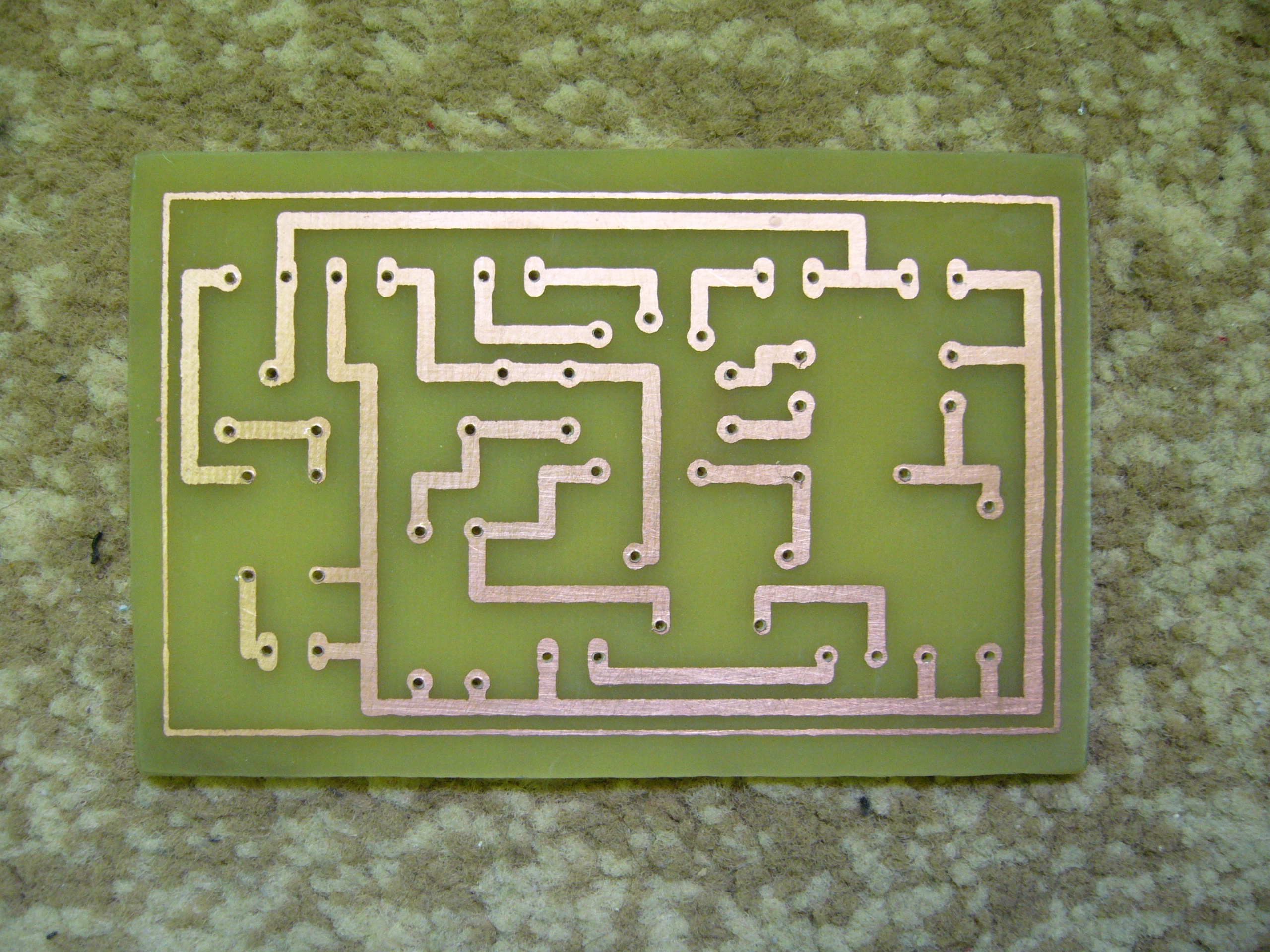
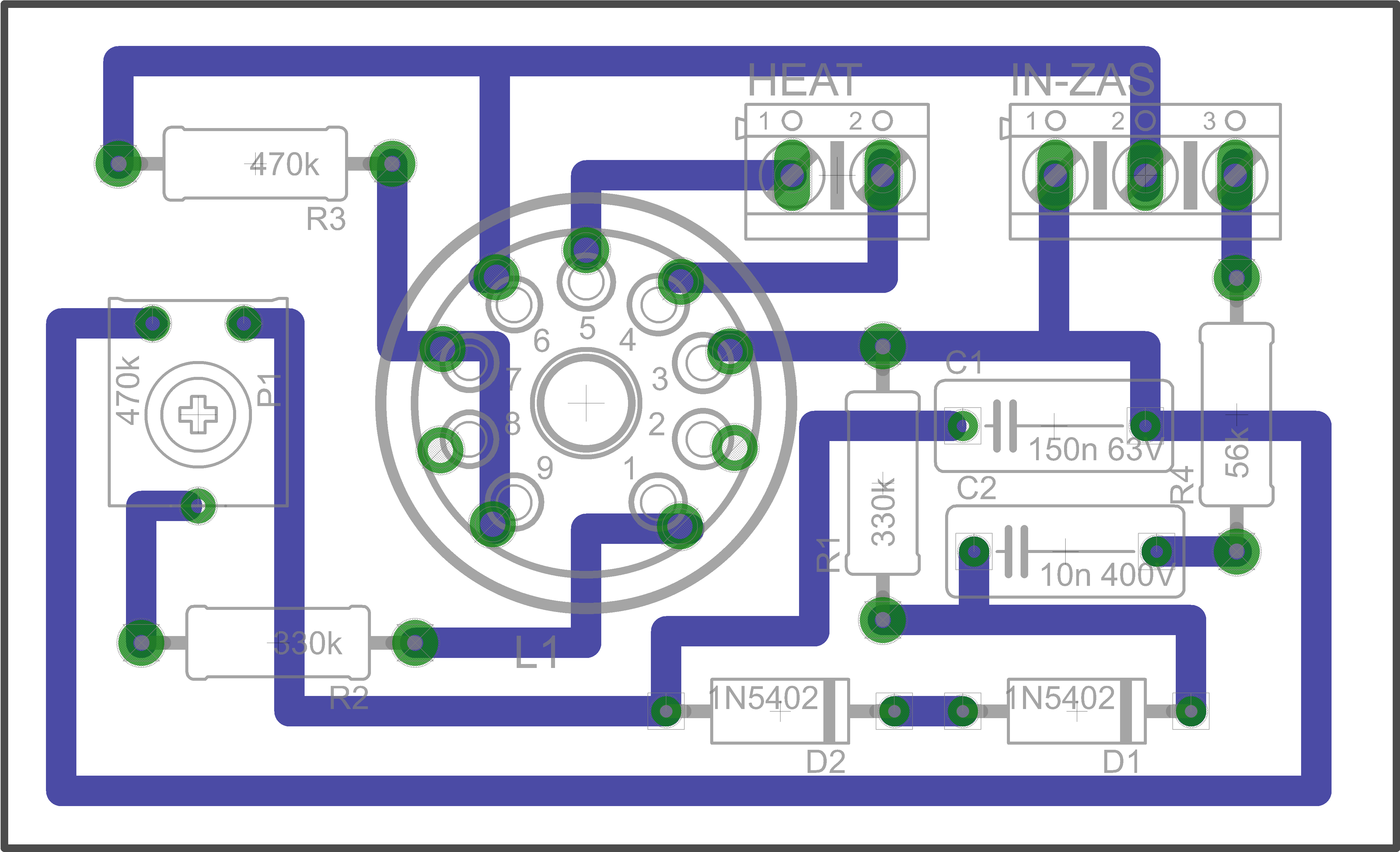
The second PCB is the mod indicator. Description of the pins of the board:
- HEAT - lamp incandescent - connect AC voltage directly from the 6.3V mains transformer - together with ECL86 lamp incandescent (in parallel)
IN-ZAS - power supply connector and feeding the input signal for the driver indicator. Looking at the graphic from the right, we have the signal input, the middle one is the power supply - we connect the high voltage there, which we take from the ECL86 amplifier board, and the leftmost terminal is ground. The potentiometer is used to set the signal level on the vacuum tube.
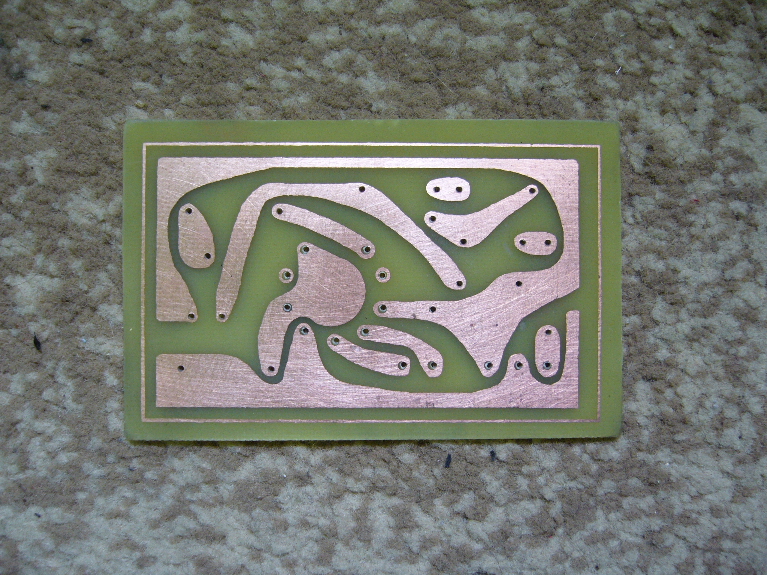
I started making PCBs
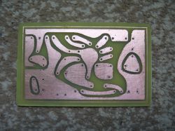
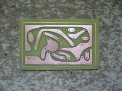
Of course, I made two PCBs of both the amplifier and the indicator.
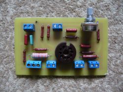
To make everything look retro, I also decided to install resistors from that era obtained from turntables.
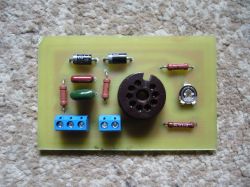
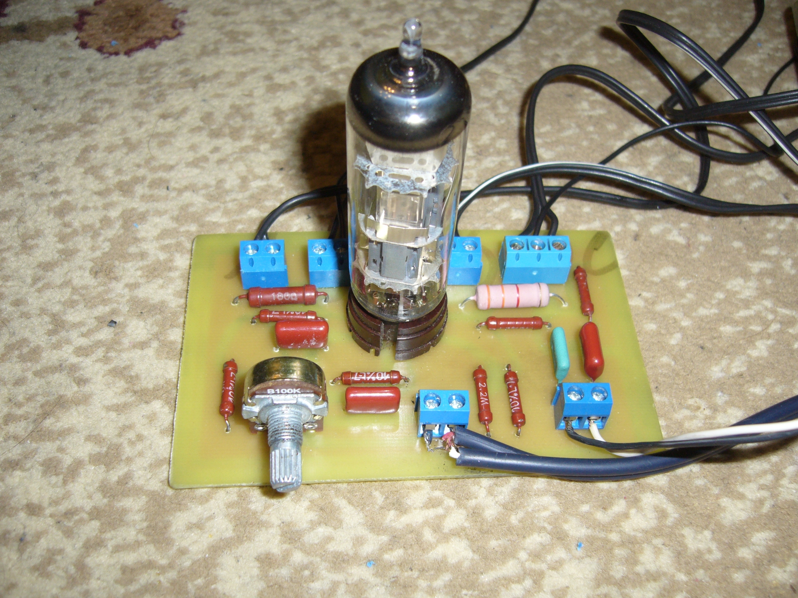
Here is the finished ECL86 amplifier board (one channel of course)
And the control indicator board

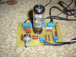
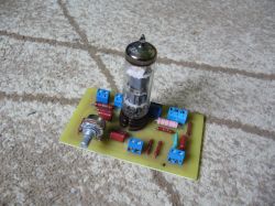
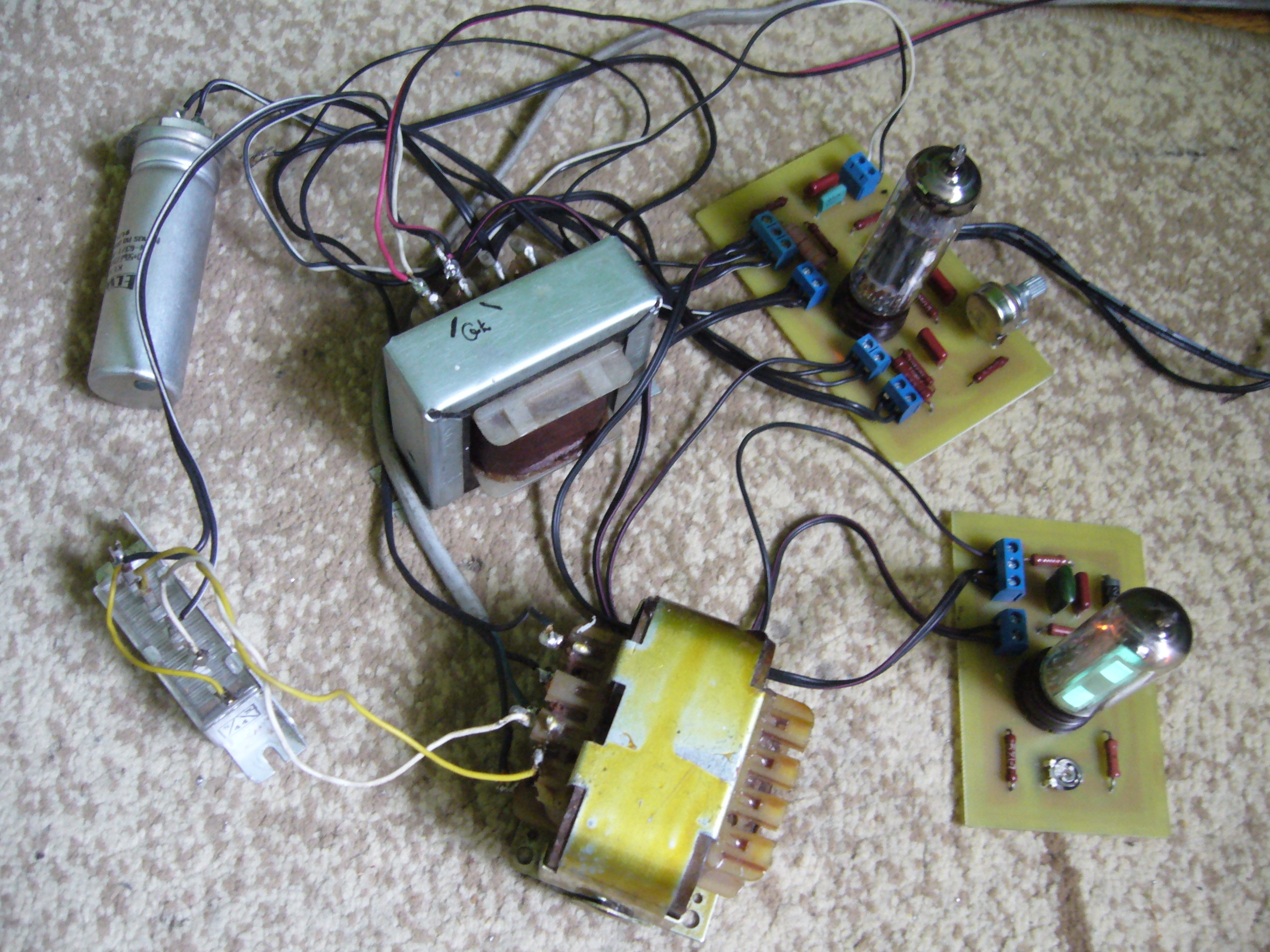
After assembling one channel, the whole thing looks like this:


The amplifier was launched - so far without an anode voltage stabilizer and without a delayed anode voltage system. These tiles are being prepared. Later, these circuits will be added and I plan to use some audio input selector. I also wanted to make an ECC83 tube preamplifier with tone correction, but so far I rejected this idea, why disturb the frequency response characteristics. There will also be an additional RIAA phono preamplifier based on an ECC83 tube. All boards with tubes will be GIMPed to make everything look nicer - the voltage stabilizer board for the delay of switching on the anode voltage and possibly the input selector will be made traditionally in Eagle.
As for the sound quality - to be honest I did not expect such a good sound from this amplifier. I used used elements in this lamps - the costs incurred by me were minimal - I had all the things, I bought a laminate and ARK connectors and 3.3k resistors because those used in Bambino were larger, so I used newer ones to fit nicely to my PCB. Total costs PLN 30 + housing costs, I think about something made of wood. There will also be costs for additional delay plates and stabilizer. But I try to do everything with the items I have. From the ZK120 or 140 magnetophone I also have an ECC83 tube so it will be used for the phono preamplifier.
But going back to the sound, I was a bit afraid of running this amplifier on a PCB - I read on the forum that bad path routing would result in hum, hum and other distortions, I designed the PCB myself and then finished the graphics in GIMP, made a thermal transfer, etched, soldered elements and commissioning - and here a pleasant surprise - nothing, no hums everything perfectly in the absence of an input signal silence, some wrote that you need to connect one leg of the radiators to the ground because there will be a hum, I did not do it and it works perfectly (of course, if necessary, you could to connect it with a cable).
After connecting the second PCB, there are no hums either. Everything works better than expected.
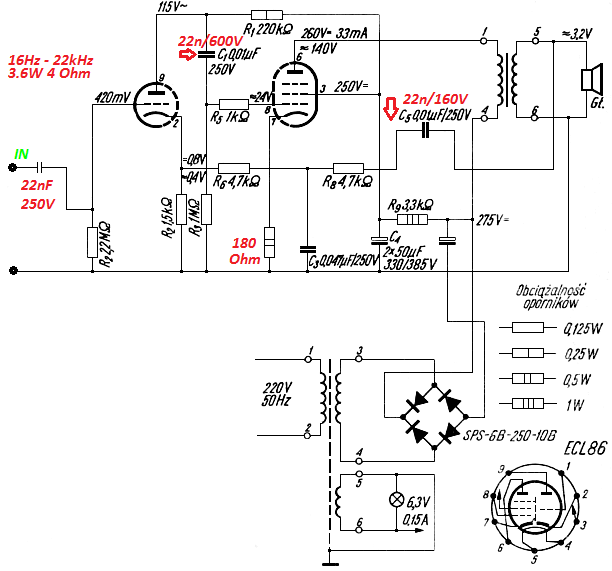
I present the diagrams, I slightly modified the original diagram from the Bambino turntable
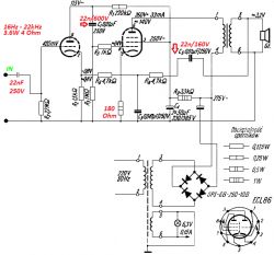
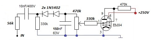
As well as the magic eye diagram
For all those who decide to make a thermal transfer plate, there are two versions in the file: in the first version, the tubes are mounted from the side of the elements (as in my case), and in the second version from the print side, which will allow the amplifier to be mounted in the housing with the protruding tubes.
Ready pdf files for thermal transfer are attached.
And now something for those who would like to get the tiles for this amp for free, as I designed the tiles, I made the track tiles in Eagle for the start, and the second set of tiles in Gimp, as I made the amp on the Gimp ones, it's the ones from Eagle so they are left for giving.
This is what the control indicator board looks like (the lamp from the elements side)
Of course, there are two pieces of these tiles to give away.
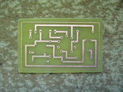
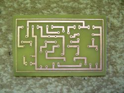
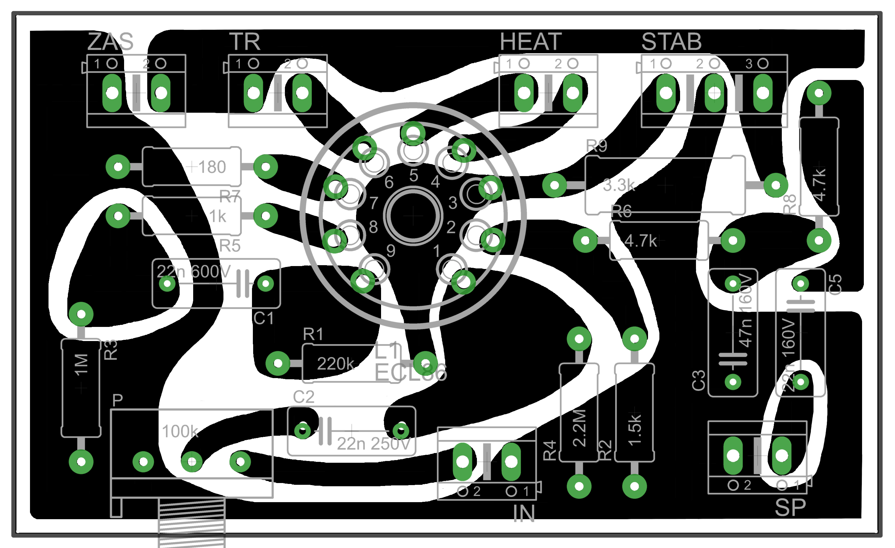
And this is what the power amplifier board looks like (the tube from the elements side)
Two pieces of these tiles are also available for donation.
I did not run the amplifier on those PCBs from Eagle - the distribution of elements is the same, the paths are different - it is difficult to say whether there will be any hum on these PCBs, especially the power amplifier ones.
Here is the distribution of elements on the Eagle boards.
And I still have a set of four PCBs to hand over, like the ones on which I made the amplifier - 100% checked.
All the tiles I have left have the correct connections and are drilled.
So, if someone wants to try to make an amplifier on these PCBs, write me a letter. I only have two sets of tiles, so the first two people who write and pick up the tiles will get them. The first person will get the GIMP version and the second person will get the Eagle version (angular paths). If it is free of charge with self-collection, and if it comes with delivery, shipping costs are reimbursed. I ship the tiles.
In case you had any questions, I'll be glad to help. I am waiting for comments, it is my twenty-fourth published project. I am asking for your understanding, I read the regulations and I think that I did everything in accordance with them.


Comments
Delayed activation of the loudspeakers is not needed if the filament and anode voltage are applied at the same time. [Read more]
How did you design funny PCBs like the amplifier one? [Read more]
Hey, there was supposed to be a delay in switching on the anode voltage but I wrote late and the error broke in, I'm correcting it, thanks for the info Of course, it is about the anode voltage, and... [Read more]
It is a pity to waste ECL86 on mine. The first one currently costs a minimum of PLN 40, as much as the new EL84. PCL86, on the other hand, PLN 10-15 for a tube with a decent emission or PLN 20 for NOS. ... [Read more]
Hello The ECL86 are recycled, so I don't feel sorry for them, besides this is my first tube amplifier so I treat it as a science. I suspect that these lamps also do not have a good emission - a colleague... [Read more]
Lamp emission can be judged from the anode current. The anode current is the drop across the cathode resistor. This drop is also the negative voltage of the first grid. Just compare with the characteristics... [Read more]
I put together a similar one, only powered from one network transformer and assembled in a spider. Nevertheless, the lamp on the tiles does not suit me, although it certainly looks nicer ... In the attachment... [Read more]
Nice, thoughtful design, but some ideas are an excess of form over content. For these lamps there is no need to use delayed anode switching, it is not the power and voltage. If this is to be a testing... [Read more]
Hey, this is the first version - just to hear the "lamp". Now I can see that with subsequent versions, if there are any, there will probably be a power supply with anode voltage stabilization - connected... [Read more]
The tube is not a transistor (anyway, stabilization is not used for transistor terminals either) - it does not require stabilized voltage, at least in a system like here. In order for the anode voltage... [Read more]
It is worth introducing stabilization for another reason. Mains voltage fluctuations. It is true that the lamps are quite resistant to exceeding parameters, but it is still worth protecting them, especially... [Read more]
Maybe someday I will also build a tube amplifier, especially since I have a tube box. It is a pity that there is no time, and several other ideas are being implemented. I will be observing the topic carefully,... [Read more]
Honestly, when I look at these tracks from Eagle, I have the impression that the designer does not know the basics of handling it. Why "broken" paths at right angles? After all, it only increases their... [Read more]
Hello The paths were designed with regard to later changes in Gimp - hence the angular ones paths I was more concerned with the distribution of elements convenient for me ... As for the PCL86 tubes,... [Read more]
Placement is one thing, routing is another. You can arrange elements in the same way, and lead paths in a completely different way, as can be seen in the description of this project. And if there were... [Read more]
The sense that they look retro and hand-drawn, I personally like them very much in combination with tube circuits because I associate them with PCBs, for example old reel to reel tape recorders, e.g. ZK120. ... [Read more]
I'm not talking about picking on. This is not my intention. As you know, when designing paths, you should, among other things, keep them as short as possible. Unfortunately, breaking them always only... [Read more]
The remark about breaking paths at sharp angles is absolutely correct. While it does not matter much in the above application, it develops good habits. Apart from that, I can see that you etched the tiles... [Read more]
Gentlemen, no exaggeration - in this project and for these frequencies, the shape and length of the tracks do not matter. He would only suggest increasing their width, there is room for it (at least for... [Read more]