MUSTOOL MDS8207 is a battery-powered multimeter with oscilloscope mode, tested after a discounted pre-order purchase of PLN 286.41 versus the current PLN 385.49.
The unit has basic DMM functions, 100 stored measurements, and oscilloscope controls including 0.5V/div to 200V/div sensitivity, 12.5ns/div to 10s/div time base, and Auto/Normal/Single triggering.
The author estimated real sine-wave bandwidth at about 30MHz to maybe 35MHz, below the specified 40MHz and 200Ms/s.
The oscilloscope has major caveats: frequency display can be wrong until the time base is changed, leads are uncompensated, and the input protection seems weak despite CAT II 1000V and CAT III 600V claims.
Generated by the language model.
I received the pre-ordered (and therefore much cheaper) MUSTOOL MDS8207 multimeter with oscilloscope function. As of today, its price is quite high, PLN 385.49, but I paid PLN 286.41.
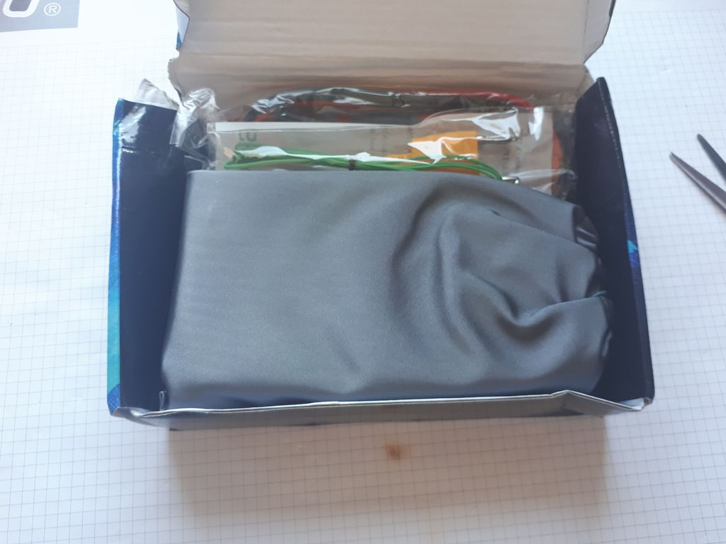
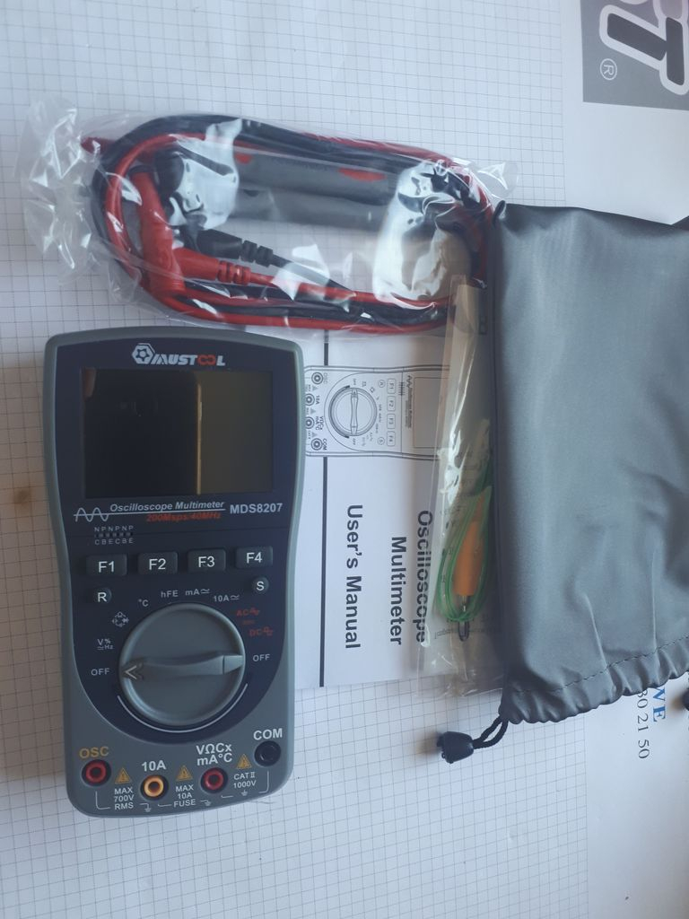
The equipment came in a cardboard box packed in a bag with the Banggood logo. The box was heavily damaged but the contents were intact. And the content is: Multimeter, test leads, K thermocouple and user manual. Plus a rag bag.
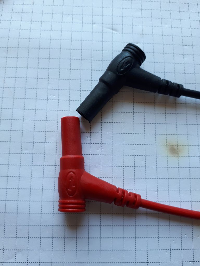
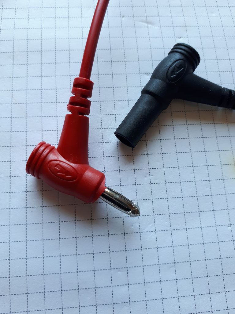
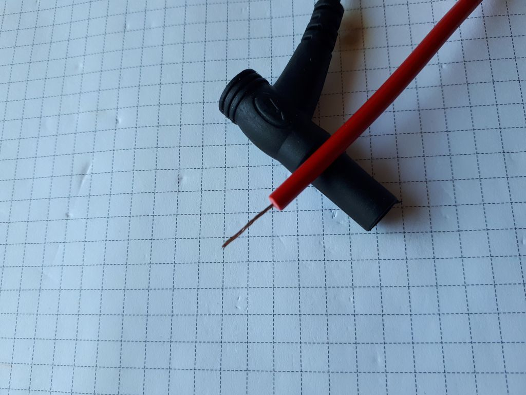
The cables make a good first impression - soft, flexible, pleasant to the touch. But the circuit continuity test showed that "something in them is not making contact". The buzzer worked once, and once it didn't, once the resistance of the circuit was 2 ohms, in a moment several hundred ohms ... The banana plugs are rather crap, and there are a few hairs inside the insulation. Probably copper, because they do not stick to the magnet, and when scraped, they do not reveal aluminum ;-)
The housing of the multimeter is ordinary hard plastic, without any rubber elements.
It's time to see how he measures: I focused on the oscilloscope function, because this is certainly what everyone is most interested in. I checked the traditional functions of the multimeter only briefly.
As for this type of equipment, it starts up quite quickly, but refreshing the measurement result is annoyingly slow.
The circuit continuity squeak works decently. Could be faster, but no drama. The probes came out blurry in the video, but you can get a general idea.
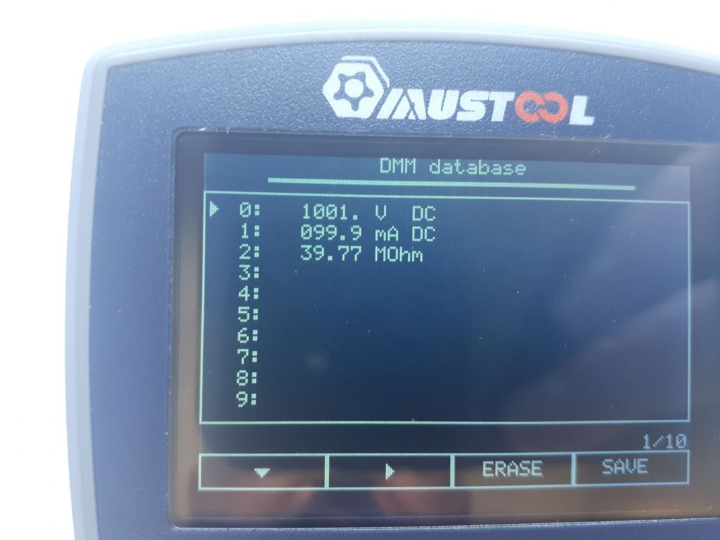
The accuracy of voltage, current and resistance measurements is OK - but as I wrote: I did not take detailed notes. They certainly fall within the specification, which is not too high (1% - 2% depending on the value and range). Up to 100 measurements can be stored in the internal memory.
The user has basic functions at his disposal, almost like in a real oscilloscope. Sensitivity from 0.5V/div to 200V/div Time base from 12.5ns/div to 10s/div Trigger on rising or falling edge in Auto, Normal and Single modes. Of course, the trigger level can be adjusted as well as the shift of the graph. The manual states that you can manipulate cursors on a frozen graph (saved in Single mode). However, I couldn't turn it on, maybe it's the fault of the first, lame, firmware. Or am I doing something wrong... It is also possible to save up to 50 waveforms, but they can only be viewed on the built-in screen - there is no way to download them in any way. During observationThe basic measurements appear on the waveform, namely: peek to peek voltage, RMS voltage, average voltage and frequency.
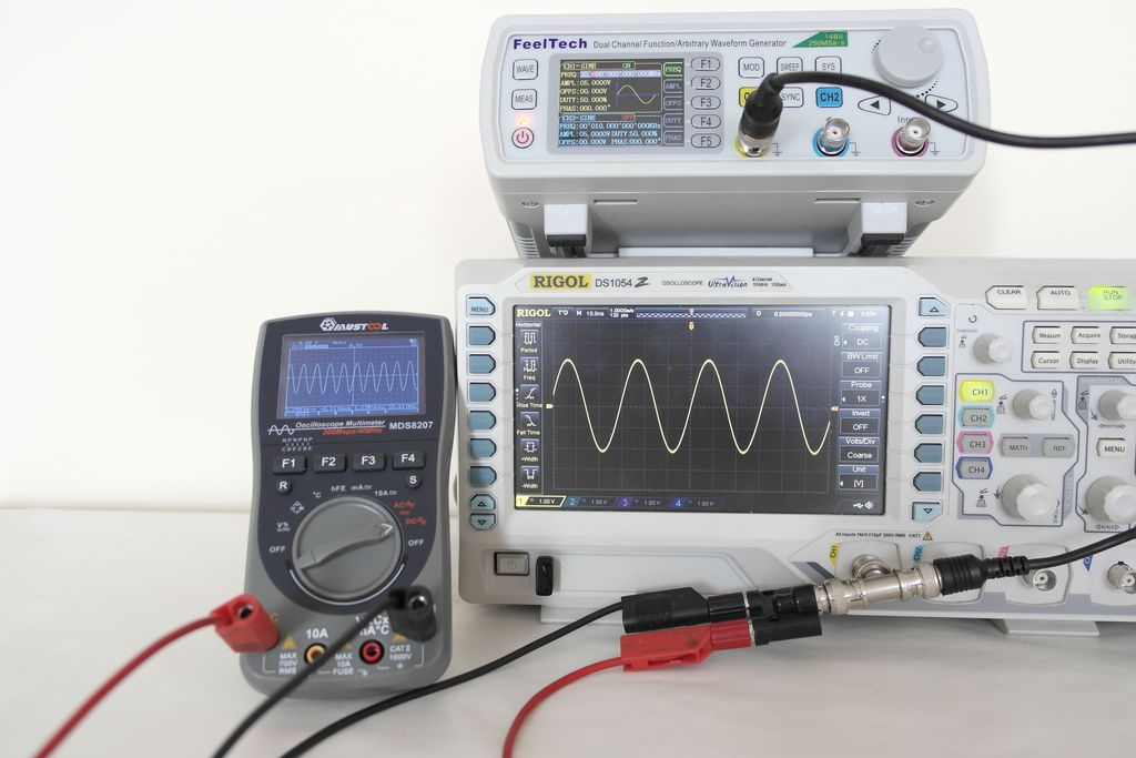
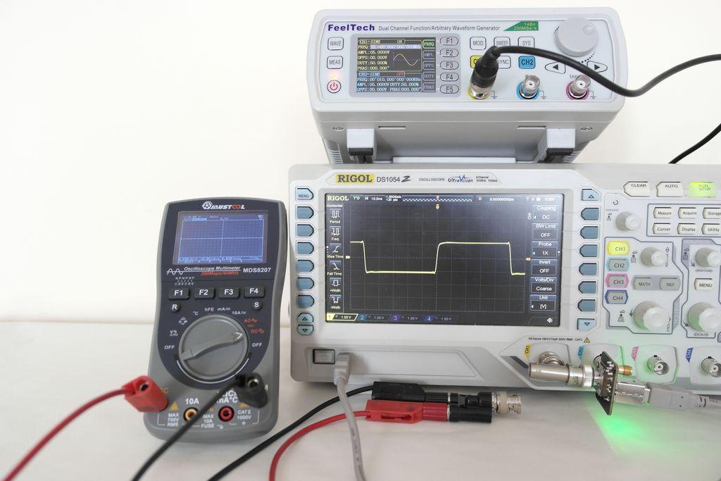
The first thing that caught my attention after connecting the generator was that the displayed frequency had nothing to do with the one from the generator. However, it turned out that changing the time base revealed the true course, but it's a big bug. If we do not know what to expect, we can be surprised - it is possible to get two stable waveforms on the screen for different time settings, and only one will be true...
Another problem, although I don't know if it can be avoided in this case, is the lack of compensation of the test leads. And while the sinusoidal waveform is imaged quite OK, the rectangle with steep edges has large overshoots. The manual mentions this and advises you to contact the manufacturer for a special shielded probe, but I put the topic aside for now ...
The specification gives 40MHz and 200Ms/s bandwidth. Using the 3dB drop in amplitude method, I estimated that the real bandwidth for the sine is about 30MHz, maybe a little more. Maybe 35MHz. I did not measure when the amplitude will be exactly 0.707 of the input, I acted a bit "by eye". ;-)
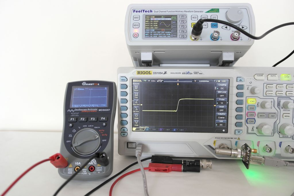
I also wanted to check the calculation method based on the rise time, but I gave up here. I have a generator with a guaranteed rise time of 40ps, which for the Gaussian method should give me the ability to test hardware up to almost 9GHz ;-)
BW = 0.35/trise The course and measurement on Rigol are shown in the photo. The measured trise is 2.3ns, which after substitution to the above formula gives over 150MHz
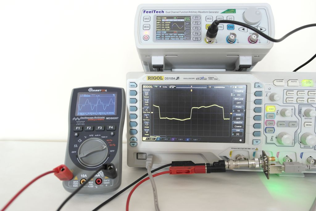
However, connecting Mustool with its cables spoils the waveform itself, and the screen shows only ringing. Some kind of compensated probe would be necessary here. My first thought was an oscilloscope probe, but I abandoned that idea when I found in the manual that "Input resistance about 100Mom".
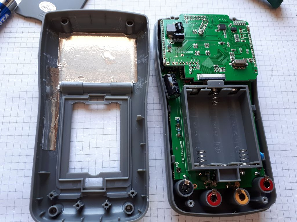
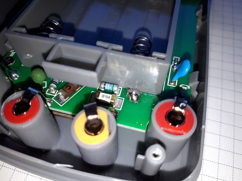
Show me what you got inside...
No fuss here as well. Two boards soldered "on a sandwich" - and you can't see much without disassembling this equipment to pieces. There are two connectors - 8pin JTAG with described pins Vcc GND TDO TDI TMS TCK, and 4pin SWD.
I am disgusted with the level of security. Here there is little (or maybe nothing) other than fuses, and the latter in the SMD version. CAT II 1000V and CAT III 600V are probably wishful thinking. And burning a fuse in the field is the end of measurements for a given day, because hardly anyone carries the equipment needed to solder a new one.
To sum up: this is not a device for everyone. And you certainly can't use this oscilloscope for serious measurements. However, as a handy device to quickly check "what's in the grass" it will be OK. Battery powered so you don't have to be overly carefuldo not short anything to ground, 700Vrms input voltage allows you to confidently manipulate mains voltages. If you could somehow compensate the frequency of the input circuit, it would be a really good device.
About Author
zgierzman wrote 1782 posts with
rating 1568 , helped 108 times.
Live in city Zgierz.
Been with us since 2005 year.
In my opinion, it is an interesting alternative to the DSO150. Despite the higher frequencies possible to measure, I chose the DSO150 because of the possibility of adding support for three digital channels.
... [Read more]
Yes, this phenomenon is as old as DSO oscilloscopes and is called aliasing. It consists in "fitting" (hence the name) of sampling into points on successive periods of the measured waveform. We obtain an... [Read more]
szymon122
27 Aug 2019 21:37
So I understand that when measuring, for example, 10MHz, the meter will show both 10MHz and, for example, 5MHz? Is there any way to check which reading is correct? [Read more]
Anonymous
28 Aug 2019 00:18
In such meters, I always wonder why such a low-quality display is installed there. It should be at least some oled. Judging by the photos, this display is not even suitable for an alarm clock ;) [Read more]
Fimek
28 Aug 2019 09:56
Hi,
Thanks for the review, the price is low, but so is the quality. For me, as a measuring instrument, it will not work.
Do any of you have experience with another cheap multimeter-oscilloscope HANTEK... [Read more]
zgierzman
28 Aug 2019 10:37
Look at this movie
The wrong waveform (at the beginning of the video) is much less stable than the right waveform (at the end).
As seen here:
If at 1MHz a rectangle can still be recognized,... [Read more]
krisRaba
28 Aug 2019 11:57
It seems to me that the target is completely different, so they did not pay attention to some things. This is an interesting tool, for example, when servicing a car or running around the production hall,... [Read more]
PawelSkrzypulec76
28 Aug 2019 13:15
Soldered SMD fuses are really an embarrassment and a disgrace for the designer. In unfavorable conditions (high energy) they will evaporate together with the solder pads to which they are soldered. [Read more]
zgierzman
28 Aug 2019 16:58
Wow, a techie. ;-D
https://obrazki.elektroda.pl/8203726100_1567004018_thumb.jpg
I found a moment for fun and with the help of this prototype I disappeared the ringing at the rapidly rising slopes.... [Read more]
Janusz_kk
28 Aug 2019 17:57
So you gave 330pF parallel to the input of the meter? [Read more]
zgierzman
28 Aug 2019 18:33
Well, 320pF, but that's a detail. For the first attempt, I had soldered wires made in a "twisted pair" to this system. Originally I was going to connect them to the generator, then I used a different... [Read more]
maciej_333
28 Aug 2019 18:47
Wouldn't it be better to connect a 1 M? resistor in parallel to the meter terminals and use a simple 1:10 passive oscilloscope probe? Additional capacitances may then be added if it is not possible... [Read more]
zgierzman
28 Aug 2019 18:57
Well, I don't know... With a 1:10 divider, measuring small voltages would probably be impossible. From 0.5V/div it would become 5V/div, which would limit the application. But already in industry, where... [Read more]
TechEkspert
28 Aug 2019 19:02
Perhaps in the next version there will be a separate BNC connector for DSO mode and an appropriate input circuit adapted to a typical 1:10 probe? [Read more]
ptero
29 Aug 2019 10:09
It's a good thing, though, that I didn't pre-purchase this meter. I will wait for version 3 :) maybe it will be better developed. It was supposed to be much better - it turned out as always :)... [Read more]
ADAM Fx
29 Sep 2019 09:33
I checked the multimeter first.
I told about my feelings in the video https://youtu.be/aWud3uwYIe4
I also added a link in the description to this topic because the article is really very good.
In general,... [Read more]
pawel_x
21 Oct 2019 16:29
There are still a lot of tests here: a total of two videos of almost 30 minutes each:
Youtube Design and Build
https://youtu.be/aILlaX9Y1Mo [Read more]
TL;DR: Mustool MDS8207 offers 10 MHz usable bandwidth despite 40 MHz spec, stores 100 readings, and consumes 140 mA; "You get what you pay for" [Elektroda, zgierzman, post #18139039] Aliasing and SMD fuses remain its main caveats.
Why it matters: Knowing the real limits and work-arounds lets you decide if this hybrid meter fits your bench or toolbox.
With 2 000 mAh cells and 140 mA draw, expect around 15 hours of continuous use; auto-off still draws 1.6 mA, so remove batteries for long storage [Elektroda, zgierzman, post #18139039]
Why do I sometimes see two different frequencies on screen?
That is aliasing. The meter samples too slowly for the chosen time base, so multiple stable but false waveforms appear [Elektroda, tzok, post #18138357] Select a finer time base or confirm with an external counter.
Up to what frequency does it show a clean square wave?
Yes. Adding ~320 pF across the input removed ringing and lifted bandwidth to about 14 MHz when used with a coax lead [Elektroda, zgierzman, post #18139798]
3-step how-to: quick input compensation
Solder a BNC jack to the input pads.
Attach a coax cable and inject a fast square wave.
Manual range selection yields about 2.5 readings per second, but AUTO adds noticeable lag while it hunts ranges [Elektroda, SlaWasII, post #18683287]
How does it compare to DSO150 or Hantek 2D42?
MDS8207 beats DSO150 on bandwidth but lacks digital channels; Hantek 2D42 offers more polish but costs roughly 2× more [Elektroda, szymon122, #18138301; Fimek, #18138979].
What edge cases should I watch for?
Standby drain can flatten batteries in weeks; aliasing can mis-read unknown signals; and blown SMD fuses require soldering gear in the field [Elektroda, zgierzman, post #18139039]


Comments
In my opinion, it is an interesting alternative to the DSO150. Despite the higher frequencies possible to measure, I chose the DSO150 because of the possibility of adding support for three digital channels. ... [Read more]
How do you estimate battery life? [Read more]
Yes, this phenomenon is as old as DSO oscilloscopes and is called aliasing. It consists in "fitting" (hence the name) of sampling into points on successive periods of the measured waveform. We obtain an... [Read more]
So I understand that when measuring, for example, 10MHz, the meter will show both 10MHz and, for example, 5MHz? Is there any way to check which reading is correct? [Read more]
In such meters, I always wonder why such a low-quality display is installed there. It should be at least some oled. Judging by the photos, this display is not even suitable for an alarm clock ;) [Read more]
Hi, Thanks for the review, the price is low, but so is the quality. For me, as a measuring instrument, it will not work. Do any of you have experience with another cheap multimeter-oscilloscope HANTEK... [Read more]
Look at this movie The wrong waveform (at the beginning of the video) is much less stable than the right waveform (at the end). As seen here: If at 1MHz a rectangle can still be recognized,... [Read more]
It seems to me that the target is completely different, so they did not pay attention to some things. This is an interesting tool, for example, when servicing a car or running around the production hall,... [Read more]
Soldered SMD fuses are really an embarrassment and a disgrace for the designer. In unfavorable conditions (high energy) they will evaporate together with the solder pads to which they are soldered. [Read more]
Wow, a techie. ;-D https://obrazki.elektroda.pl/8203726100_1567004018_thumb.jpg I found a moment for fun and with the help of this prototype I disappeared the ringing at the rapidly rising slopes.... [Read more]
So you gave 330pF parallel to the input of the meter? [Read more]
Well, 320pF, but that's a detail. For the first attempt, I had soldered wires made in a "twisted pair" to this system. Originally I was going to connect them to the generator, then I used a different... [Read more]
Wouldn't it be better to connect a 1 M? resistor in parallel to the meter terminals and use a simple 1:10 passive oscilloscope probe? Additional capacitances may then be added if it is not possible... [Read more]
Well, I don't know... With a 1:10 divider, measuring small voltages would probably be impossible. From 0.5V/div it would become 5V/div, which would limit the application. But already in industry, where... [Read more]
Perhaps in the next version there will be a separate BNC connector for DSO mode and an appropriate input circuit adapted to a typical 1:10 probe? [Read more]
It's a good thing, though, that I didn't pre-purchase this meter. I will wait for version 3 :) maybe it will be better developed. It was supposed to be much better - it turned out as always :)... [Read more]
I checked the multimeter first. I told about my feelings in the video https://youtu.be/aWud3uwYIe4 I also added a link in the description to this topic because the article is really very good. In general,... [Read more]
There are still a lot of tests here: a total of two videos of almost 30 minutes each: Youtube Design and Build https://youtu.be/aILlaX9Y1Mo [Read more]
So is it worth it or not? [Read more]