FAQ
TL;DR: The DIY 0-30 V / 0-10 A supply delivers up to 300 W peak and was praised as a "nice design" [Elektroda, Freddy, post #18877408] All-analog LM723 control, single-layer 92 × 72 mm PCB, <0.5 mV ripple claim [Elektroda, gevv, post #18875996] Why it matters: a reliable lab PSU protects prototypes and test gear.
Quick Facts
• Output range: 0-30 V, 0-10 A (8 A continuous, 10 A peak) [Elektroda, gevv, post #18875996]
• Ripple spec: ≤0.5 mV rms (measured values often 1-3 mV) [Elektroda, Anonymous, post #18876715]
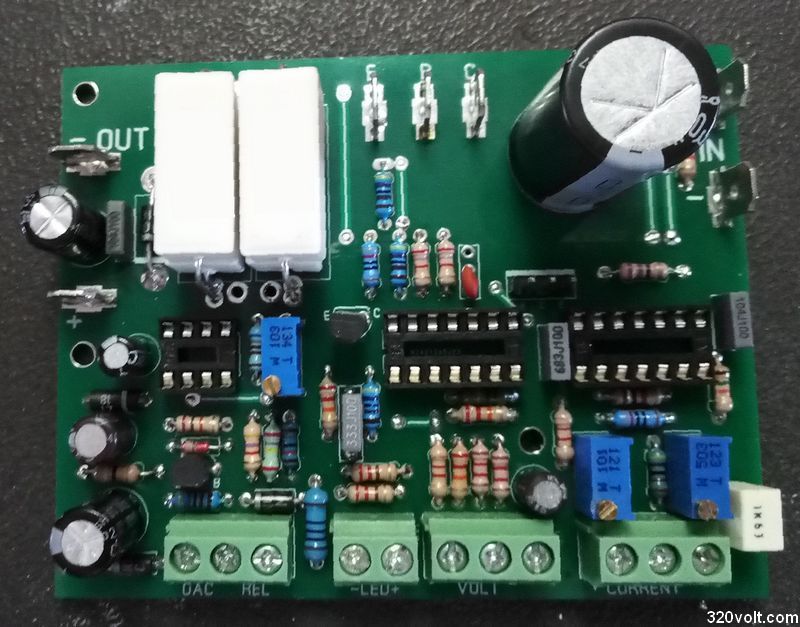
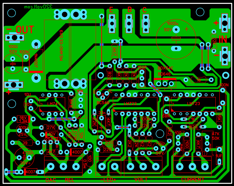
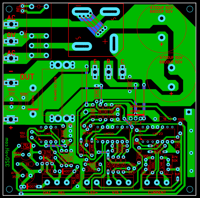
• Control board footprint: 91.6 × 72.2 mm, single-layer, Sprint-Layout format [Elektroda, gevv, post #18875996]
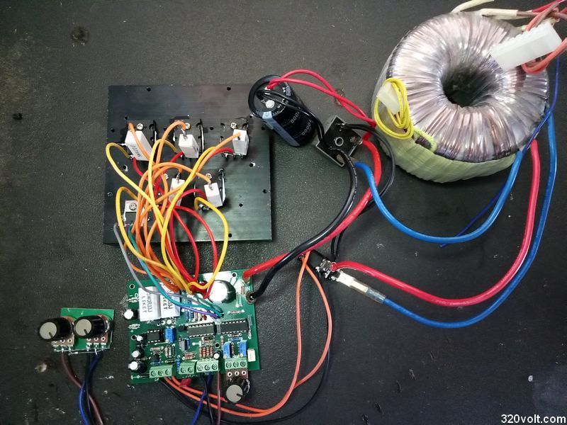
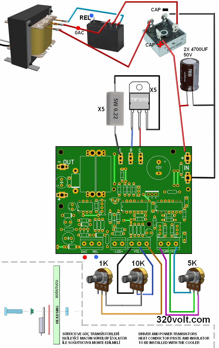
• Typical transformer: 2 × 15 V, ≥300 VA toroid, 5 kg weight [Elektroda, worlinx, post #18906117]
• Parts cost: approx. 55-80 € with new semiconductors and heat-sink [Elektroda, 321Tobiasz123, post #18897380]
Is the 0.5 mV ripple figure realistic?
Why is a logarithmic potentiometer used for current adjustment?
Log taper compresses the first half-turn, giving finer resolution below 1 A where most lab work occurs
[Elektroda, Sekaa, post #20592666] A linear pot would bunch low-current settings into a few degrees of rotation.
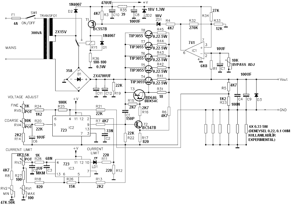
What does resistor R36 do?
Is the LM723 controller safe when a charged battery back-feeds the output?
Reverse voltage can destroy the pass transistor and LM723. Fit diode D3 across the output and add a fast 10 A fuse; the fuse clears before the diode overheats
[Elektroda, 398216, post #18925071]
How much will the parts cost in 2025?
Which transformer rating ensures full 0-30 V at 10 A?
Can I upgrade to 0-50 V output by fitting a 2 × 23 V transformer?
Yes, but raise electrolytic ratings to 63 V, recalculate R5/R23 for 7.15 mA reference current, and derate the pass-transistor dissipation (up to 500 W worst case)
[Elektroda, sahamipoor, post #19649417]
Why do C9 and other large capacitors overheat?
How can I tame the high inrush current during a short-circuit test?
- Add a 0.22 Ω 5 W series resistor between rectifier and filter. 2. Reduce C9 to 10 µF. 3. Enable current-limit LED before output relay closes. Builders report sparks drop by 80 % [Elektroda, sahamipoor, post #20587719]
Should the PSU have an output fuse?
Do I need a case, meters, and fan?
How to create a toner-transfer PCB from the Sprint-Layout file?
- Open the free Sprint-Layout 6.0 Viewer; select File ➝ Print. 2. Tick “Mirror” and choose 600 dpi. 3. Print on glossy magazine paper, iron onto copper, etch. Users report <1 hour board time [Elektroda, AdamC, post #19924035]
Edge case: what fails first if cooling is poor?
3-step guide: choosing the filter capacitance
Generated by the language model.

Comments
It is a pity that you did not describe this power supply, at least a little in your own words. Write something about him. [Read more]
@gevv What's yours here, because apart from the first sentence, everything comes from the source page. You may be the author of it, but nothing seems to indicate it yet. [Read more]
Hello, Excuse me. What category is suitable for sharing? [Read more]
My friend is from Turkey, so it is difficult for him to write in Polish. Greetings [Read more]
It may be this, but only after you complete the description - it must be more precise, not just one sentence. Show schematic and PCB. If you have a problem with writing in Polish, write a description... [Read more]
Hello, Corrected. Thanks. [Read more]
Since the "laboratory power supply" should (?) Have a housing, current and voltage meters? As it stands it is just an idea for a power supply. In addition, I miss the oscillograms of the output voltage... [Read more]
Plusik for originality and complete documentation. The housing depends on the transformer and heat sink you have. I do not believe in the 0.5mV ripple at the output. [Read more]
@gevv Thanks for the correction - greetings and congratulations on the nice design. [Read more]
Hello, File updated, motherboard and DC 100X100mm PCB connection https://obrazki.elektroda.pl/4302232700_1599331616.png [Read more]
Stabilizer 723 does not cause problems? The system is resistant to voltage applied to the output? This happens, for example, when a battery is connected to the switched off power supply. [Read more]
Cool design. What is the approximate cost of parts for the construction of such a power supply? [Read more]
The filtration in the power supply is very poor, the 10mF capacitor will not live for too long, because you exceed its operating current (it will simply boil). [Read more]
Where do you see a 10mF capacitor because I can't find it? [Read more]
In the video 0:41 the question is whether only for testing or ultimately. [Read more]
C11 and C12 in the diagram, on pcb you can see in # 11 that he has a lot of space for them. Let's face it, if someone actually uses a solid hit and will constantly charge 5A or more, it needs to... [Read more]
Well, it's 2x4700uF, not a 10mF capacitor, and that's the difference. I am curious about the justification of this current of work. Are you not exaggerating with these capacities? [Read more]
I must admit that I would also like to learn something new ... How would the operation with 100Hz supercharging "boil" a capacitor? I would not like to be smart, but does it not depend (probably about... [Read more]
As for me: 1. 2x15v on a hit is not enough for a 0-30v 10A power supply 2. 2x4m7 in filtration - too little, but see point one 3. it is not feasible to achieve the range of 0V and 0mA without supporting... [Read more]