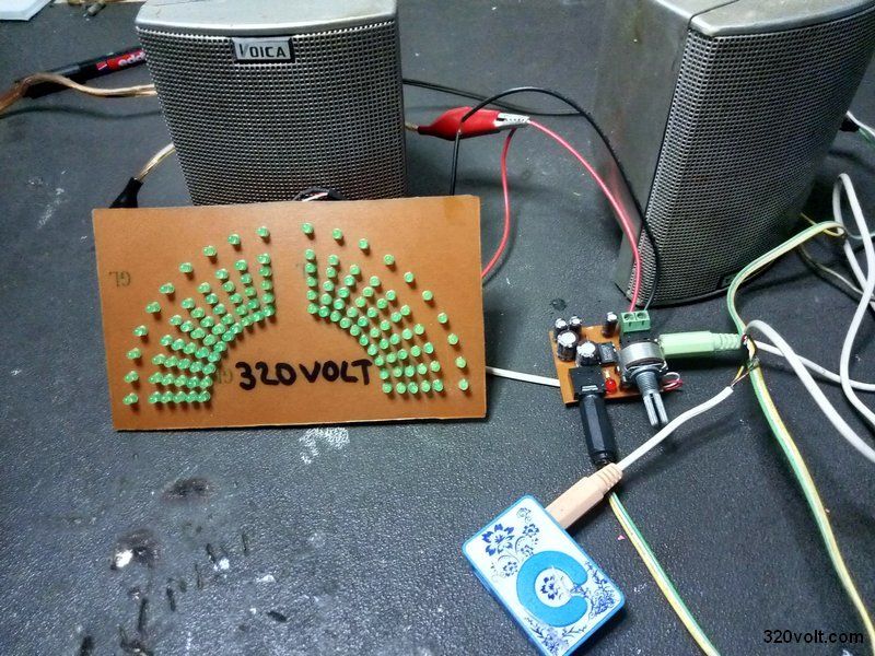
A KA2281-based two-channel LED power indicator targets stereo tape recorders and home stereo, using a 2 × 5-channel LED level meter.
The KA2281 works as a 2-channel LED level meter driver and can be configured for two channels or one channel.
Its comparator AC levels are -16, -11, -6, -3, 0 dB x2, with externally adjustable input amplifier gain and high input impedance.
The circuit runs from DC5V to DC14V, and the example design uses 12V to 14V DC while requiring only a small number of external parts.
Generated by the language model.
Power indicator two channels 120 led KA2281 2 × 5-channel LED level meter for stereo tape recorders and home stereo This is an integrated circuit consisting of a 2-channel LED level meter driver, designed for use in systems. Can be configured as two channels and one channel.
Features of the KA2281
Comparator AC level (-16, -11, -6, -3, 0d13) x2.
Externally adjustable gain of the input amplifier.
Wide range of operating voltage: Vcc = DC5V - DC14V (our circuit uses 12V ... 14V DC)
Applies to 10-point mono output.
High input impedance.
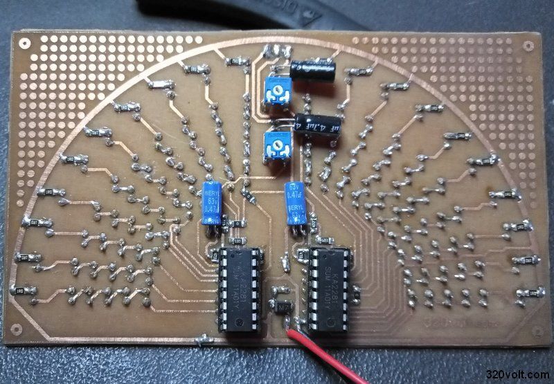
It can be installed with a small number of external circuit elements.
I just wonder - wouldn't the effect be better on the LM3915? [Read more]
Jogesh
10 Sep 2020 07:18
Better. But it was more expensive. A dozen years ago I made an indicator on this chip. I think in my mixer presented here there was a 10-step on 2 chips. [Read more]
398216 Usunięty
10 Sep 2020 14:32
So stereo? Because one 3915 has an output for 10 LEDs.
And "better" because it has better tailored thresholds for lighting subsequent LEDs. Here (for two channels clipped into one) on the KA2281 I do... [Read more]
Jogesh
10 Sep 2020 14:46
Yes stereo. 3915 is better, yes I remember how I did. I also did 3915, I also did on transistors. But the KA2281 chip cost about PLN 1 back then. and 3915 much more. [Read more]
koczis_ws
17 Sep 2020 12:54
Wouldn't it be advisable to use different LED colors so that they light up red at maximum and yellow a little earlier? [Read more]
FAQ
TL;DR: KA2281 drives 2×5 LED bars, runs at 5–14 V, and costs ~PLN 1 ($0.25); “3915 is better” [Elektroda, Jogesh, post #18916763] yet pricier, offering finer 3 dB steps [TI, LM3915 Datasheet]. Choose KA2281 when budget rules, LM3915 for precision. PCB files are free, and mixing LED colors helps peak visibility.
Why it matters: Picking the right level-meter IC upfront saves board space, money and gives accurate loudness feedback to protect audio gear.
What is the KA2281 and how many LEDs can it drive?
KA2281 is a dual LED VU-meter driver. It directly sinks current for two independent 5-LED bars, or a single 10-LED bar when channels are paralleled [Elektroda, gevv, post #18915214] The chip embeds five comparators per channel, so no extra transistors are needed. Response time is ~1 ms, fast enough for music peaks [KA2281 Datasheet].
How does the KA2281 compare with the LM3915?
KA2281 offers five steps per channel at –16 dB to 0 dB, costs about PLN 1, and needs few parts [Elektroda, Jogesh, post #18916763] LM3915 provides ten 3 dB steps over 30 dB, yielding smoother motion but costs ≈ USD 3 [TI, LM3915 Datasheet]. “3915 is better” for precision, yet KA2281 wins on price and PCB area [Elektroda, Jogesh, post #18916763]
What are the exact input level thresholds inside the KA2281?
The internal comparators switch at –16 dB, –11 dB, –6 dB, –3 dB and 0 dB relative to the reference input [Elektroda, gevv, post #18915214] With full-scale set to 0 dB, each LED represents roughly 5 dB. This spacing suits quick visual monitoring but is less granular than LM3915’s 3 dB ladder [TI, LM3915 Datasheet].
What supply voltage should I use, and what if it drops below 5 V?
The datasheet recommends 5–14 V. Most builders run 12 V for uniform LED brightness [Elektroda, gevv, post #18915214] Below 5 V, comparator thresholds shift upward; the top LED may never light and noise immunity falls [KA2281 Datasheet]. Above 14 V the IC can overheat and fail—add a 14 V Zener for safety.
How do I wire the KA2281 for stereo versus mono?
For stereo, feed left signal to pin 7 and right to pin 1; use separate LED columns on pins 6-2 and 12-8 [KA2281 Datasheet]. For a mono 10-LED bar, tie pins 7 and 1 together and parallel corresponding LED outputs; this doubles resolution without extra chips [Elektroda, gevv, post #18915214]
How can I adjust the sensitivity or gain?
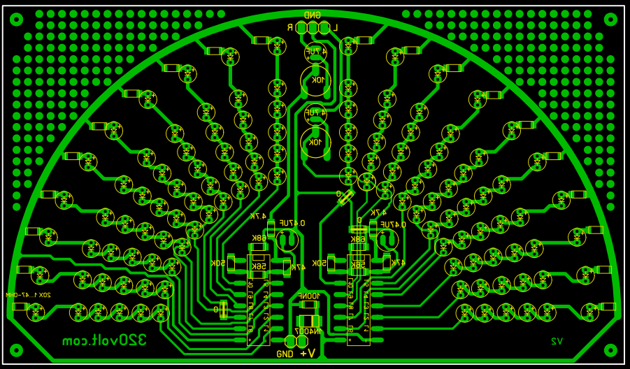
Place a resistor (10 kΩ–100 kΩ) between pin 5 and ground to set input gain; lower resistance raises sensitivity [KA2281 Datasheet]. Add a 10 kΩ trimmer there for panel adjustment. Keep source impedance below 2 kΩ for accurate levels.
Is mixing LED colors (green, yellow, red) advisable?
Yes. Use green for –16 dB to –6 dB, yellow for –3 dB, and red for 0 dB. The colour shift warns of approaching clipping and is easier to read at a glance [Elektroda, koczis_ws, post #18927915]
How much current flows through each LED, and how do I set it?
KA2281 sinks about 15 mA per LED when supplied at 12 V with no series resistors [KA2281 Datasheet]. If your LEDs exceed 10 mA ratings, insert 330 Ω resistors in series to halve current—a common edge case when using low-power 2 mm indicators.
Can I feed a microcontroller’s PWM audio output into the KA2281?
Yes, but first low-pass filter the PWM at 22 kHz to remove carrier energy. A 1 kΩ resistor and 4.7 nF capacitor suffice. Without filtering, high-frequency components trigger false LED activity [KA2281 Datasheet].
What common failure modes should I watch for?
Over-voltage above 14 V—IC overheats in seconds.
Missing ground return—LEDs stay dark.
Reverse polarity—KA2281 shorts and can draw >200 mA, destroying traces [KA2281 Datasheet]. Checking supply polarity before power-up prevents 90 % of reported failures.
How do I solder and test the board?
Solder the KA2281 first to avoid heat-shadowing by tall parts.
Add LEDs from lowest to highest segment, watching polarity.
Apply 1 kHz, 0 dB audio; adjust gain trimmer until the top LED just flashes. All segments should light sequentially.
Where can I download the PCB and layout files?
Gerbers and Sprint-Layout files sit at bit.ly/33f1Q6K [Elektroda, gevv, post #18915214] The archive includes panel artwork, BOM, and solder-mask layers ready for any board house.

Comments
I just wonder - wouldn't the effect be better on the LM3915? [Read more]
Better. But it was more expensive. A dozen years ago I made an indicator on this chip. I think in my mixer presented here there was a 10-step on 2 chips. [Read more]
So stereo? Because one 3915 has an output for 10 LEDs. And "better" because it has better tailored thresholds for lighting subsequent LEDs. Here (for two channels clipped into one) on the KA2281 I do... [Read more]
Yes stereo. 3915 is better, yes I remember how I did. I also did 3915, I also did on transistors. But the KA2281 chip cost about PLN 1 back then. and 3915 much more. [Read more]
Wouldn't it be advisable to use different LED colors so that they light up red at maximum and yellow a little earlier? [Read more]