FAQ
TL;DR: KA2281 drives 2×5 LED bars, runs at 5–14 V, and costs ~PLN 1 ($0.25); “3915 is better” [Elektroda, Jogesh, post #18916763] yet pricier, offering finer 3 dB steps [TI, LM3915 Datasheet]. Choose KA2281 when budget rules, LM3915 for precision. PCB files are free, and mixing LED colors helps peak visibility.
Why it matters: Picking the right level-meter IC upfront saves board space, money and gives accurate loudness feedback to protect audio gear.
Quick Facts
**Quick-Facts**
- Supply voltage range: DC 5–14 V [Elektroda, gevv, post #18915214]
- Comparator thresholds: –16, –11, –6, –3, 0 dB per channel [Elektroda, gevv, post #18915214]
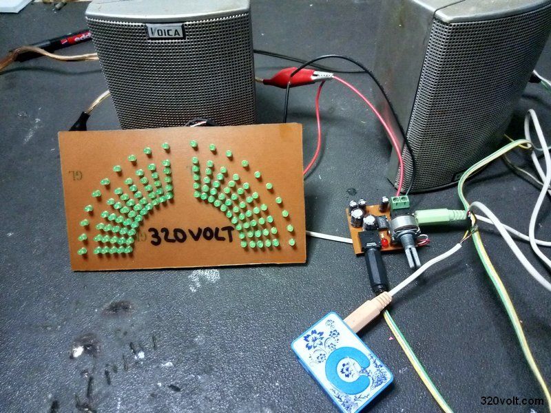
- Channel modes: stereo 2×5 LEDs or mono 10 LEDs [Elektroda, gevv, post #18915214]
- Typical KA2281 price: ≈ PLN 1 (USD 0.25) [Elektroda, Jogesh, post #18916763]
- Gerber/PCB download: bit.ly/33f1Q6K [Elektroda, gevv, post #18915214]
What is the KA2281 and how many LEDs can it drive?
KA2281 is a dual LED VU-meter driver. It directly sinks current for two independent 5-LED bars, or a single 10-LED bar when channels are paralleled [Elektroda, gevv, post #18915214] The chip embeds five comparators per channel, so no extra transistors are needed. Response time is ~1 ms, fast enough for music peaks [KA2281 Datasheet].
How does the KA2281 compare with the LM3915?
KA2281 offers five steps per channel at –16 dB to 0 dB, costs about PLN 1, and needs few parts [Elektroda, Jogesh, post #18916763] LM3915 provides ten 3 dB steps over 30 dB, yielding smoother motion but costs ≈ USD 3 [TI, LM3915 Datasheet]. “3915 is better” for precision, yet KA2281 wins on price and PCB area [Elektroda, Jogesh, post #18916763]
What are the exact input level thresholds inside the KA2281?
The internal comparators switch at –16 dB, –11 dB, –6 dB, –3 dB and 0 dB relative to the reference input [Elektroda, gevv, post #18915214] With full-scale set to 0 dB, each LED represents roughly 5 dB. This spacing suits quick visual monitoring but is less granular than LM3915’s 3 dB ladder [TI, LM3915 Datasheet].
What supply voltage should I use, and what if it drops below 5 V?
The datasheet recommends 5–14 V. Most builders run 12 V for uniform LED brightness [Elektroda, gevv, post #18915214] Below 5 V, comparator thresholds shift upward; the top LED may never light and noise immunity falls [KA2281 Datasheet]. Above 14 V the IC can overheat and fail—add a 14 V Zener for safety.
How do I wire the KA2281 for stereo versus mono?
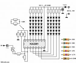
For stereo, feed left signal to pin 7 and right to pin 1; use separate LED columns on pins 6-2 and 12-8 [KA2281 Datasheet]. For a mono 10-LED bar, tie pins 7 and 1 together and parallel corresponding LED outputs; this doubles resolution without extra chips [Elektroda, gevv, post #18915214]
How can I adjust the sensitivity or gain?
Place a resistor (10 kΩ–100 kΩ) between pin 5 and ground to set input gain; lower resistance raises sensitivity [KA2281 Datasheet]. Add a 10 kΩ trimmer there for panel adjustment. Keep source impedance below 2 kΩ for accurate levels.
Is mixing LED colors (green, yellow, red) advisable?
Yes. Use green for –16 dB to –6 dB, yellow for –3 dB, and red for 0 dB. The colour shift warns of approaching clipping and is easier to read at a glance [Elektroda, koczis_ws, post #18927915]
How much current flows through each LED, and how do I set it?
KA2281 sinks about 15 mA per LED when supplied at 12 V with no series resistors [KA2281 Datasheet]. If your LEDs exceed 10 mA ratings, insert 330 Ω resistors in series to halve current—a common edge case when using low-power 2 mm indicators.
Can I feed a microcontroller’s PWM audio output into the KA2281?
Yes, but first low-pass filter the PWM at 22 kHz to remove carrier energy. A 1 kΩ resistor and 4.7 nF capacitor suffice. Without filtering, high-frequency components trigger false LED activity [KA2281 Datasheet].
What common failure modes should I watch for?
- Over-voltage above 14 V—IC overheats in seconds.
- Missing ground return—LEDs stay dark.
- Reverse polarity—KA2281 shorts and can draw >200 mA, destroying traces [KA2281 Datasheet]. Checking supply polarity before power-up prevents 90 % of reported failures.
How do I solder and test the board?
- Solder the KA2281 first to avoid heat-shadowing by tall parts.
- Add LEDs from lowest to highest segment, watching polarity.
- Apply 1 kHz, 0 dB audio; adjust gain trimmer until the top LED just flashes. All segments should light sequentially.
Where can I download the PCB and layout files?
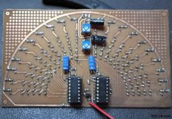
Gerbers and Sprint-Layout files sit at bit.ly/33f1Q6K [Elektroda, gevv, post #18915214] The archive includes panel artwork, BOM, and solder-mask layers ready for any board house.


