Hi
Some time ago I got some audio equipment in RACK housings.
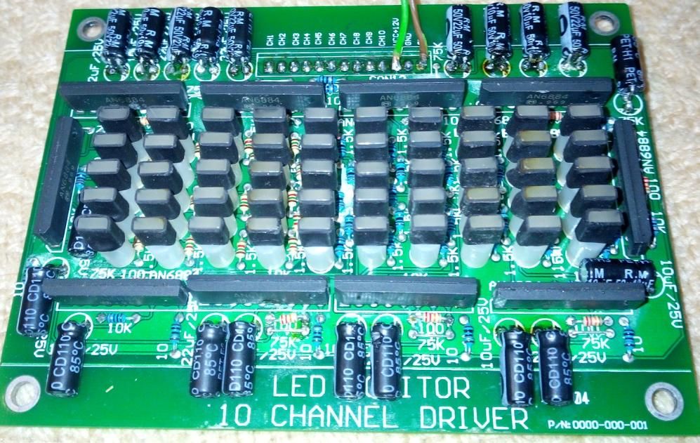
In one of them there was a 10-channel signal level indicator board and it asked to build a spectrum analyzer.
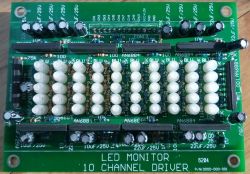
The board has ten AN6884 chips and 50 3mm red LEDs, but the module was adapted to indicate a voltage level of 100 V (it was radio equipment).
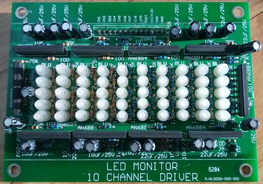
The first thing I did was get rid of the voltage dividers, place the capacitors and replace the diodes with green and red 2x5 mm MILK.
It looks like this now.

The module started with the so-called "kick", now filters would come in handy.
Two topics came to the rescue.
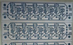
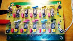
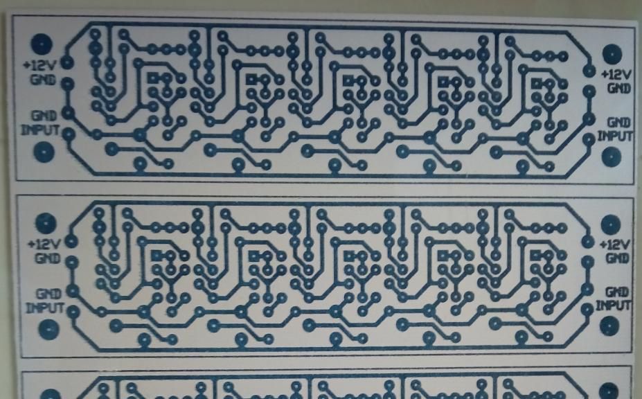
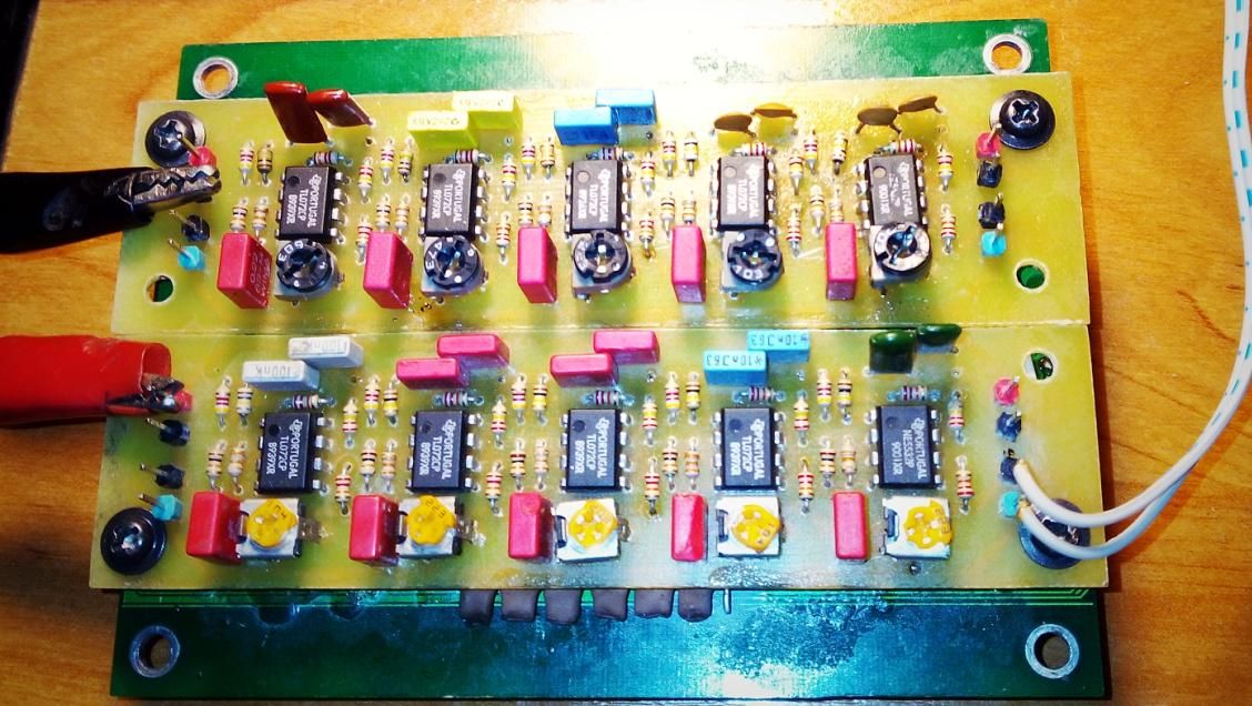
https://www.elektroda.pl/rtvforum/topic560625.html https://www.elektroda.pl/rtvforum/topic1471378.html The filters are two plates with 5 completely separate filters, connected by ground and signal.
The power supply is 12 V, each filter has an artificial ground system and is powered from the main rail through a 1 k? resistor, thanks to which the system does not excite and the filters do not have any influence on each other (during tests with a common power supply and artificial ground, it happened often) .
Capacitors selected experimentally and like this:
CH1 - 100nF, frequency - approx. 50Hz
CH2 - 47nF, frequency - approx. 100Hz
CH3 - 22nF, frequency - approx. 200Hz
CH4 - 10nF, frequency - approx. 500Hz
CH5 - 4.7nF, frequency - about 1kHz
CH6 - 3.3nF, frequency - about 1.8kHz
CH7 - 2.2nF, frequency - about 2.5kHz
CH8 - 1nF, frequency - around 5kHz
CH9 - 470pF, frequency - about 10kHz
CH10 - 220pF, frequency - approx. 18Hz (too much here)
The sensitivity of each band is adjustable.
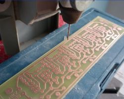
Tiles - thermo transfer.
Figure in the attachment.
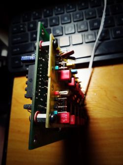
... and TADAM!
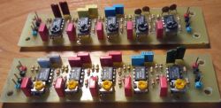
This is what the whole thing looks like.
Videos of how the system works, test first:
[movie: 1811e91b9f]
https://filmy.elektroda.pl/21_1603035284.mp4 [/ movie: 1811e91b9f]
And music:
[movie: 1811e91b9f]
https://filmy.elektroda.pl/38_1603035320.mp4 [/ movie: 1811e91b9f]
WARNING!
If someone wants to make a PCB, remember to cut the +12 V paths to each filter and solder the 1 k? resistors to the intersection.
I have SMD 1206.


Comments
Everything is fine, but (as always, I have to ask) what is the threshold between individual LEDs? In addition, 5 LEDs per channel are still a little bit to talk about an analyzer - if it is about an "audio... [Read more]
For a professional analyzer, there are not enough diodes, not enough bands and no specific division (thirds, octaves, or whatever), but I was supposed to call it Equalizer as some? :) Of course, this... [Read more]
What program do you design PCBs in? [Read more]
Trax Maker + Circuit Maker Package. A gift from the 90s from a friend from the USA. [Read more]
Band Blinker sounds like "professional" :D Good old soft. After several years of using it (10 points x 11 channels), it seems to me that a minimum of 20 points per channel and 10-16 channels would... [Read more]
In my youth, I followed the line of least resistance and connected the Equalizer with 2x12 strands to the sliders with assembled sets of scales from Jablo. I made a separate box for the analyzer and glued... [Read more]
For home, 10 points in 10 bands are enough. Ultimately, the smallest stage EQ has only 16 bands. As for the number of LEDs in the bollard - a lot depends on the thresholds of their arrangement. A good... [Read more]
One more video. [Read more]
As always, I must praise you for using the elements and components that are left in the home, and for making everything from scratch. You made this analyzer nice and aesthetic, I mean tiles. The end result,... [Read more]