FAQ
TL;DR: A dual-VU retrofit based on LM358 (slew rate 0.3 V/µs [TI, 2023]) works, but “an indicator must show something specific” [Elektroda, 398216, post #19377816] Adding a diode-log converter or switching to TL084 (3 MHz GBW [TI, 2023]) gives smoother, calibrated dB response.
Why it matters: Correct scaling turns a flashing gadget into a true level meter that protects recordings and speakers.
Quick Facts
• LM358 open-loop gain: 100 dB typ.; slew rate 0.3 V/µs [TI, 2023]
• TL084 GBW: 3 MHz; slew rate 13 V/µs [TI, 2023]
• Standard VU reference: 0 dB = 0.775 Vrms (+4 dBu) [AES, 2018]
• Typical displacement coil: 1 mA full-scale, 650 Ω [Bourns, 2022]
• Recommended meter attack/decay: 300 ms / 1 s [IEC 60268-17]
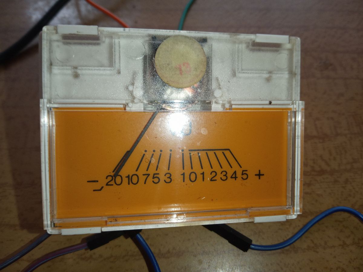
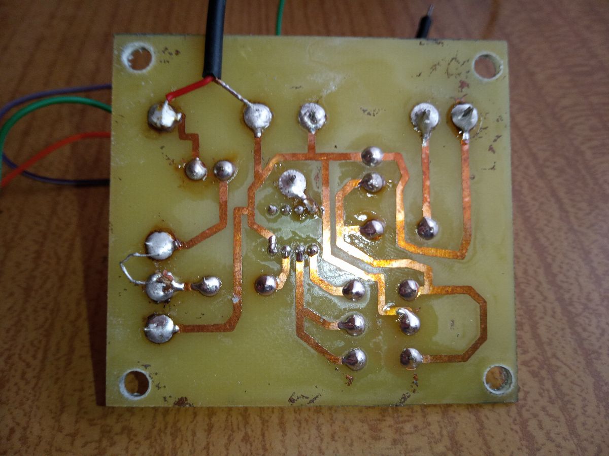
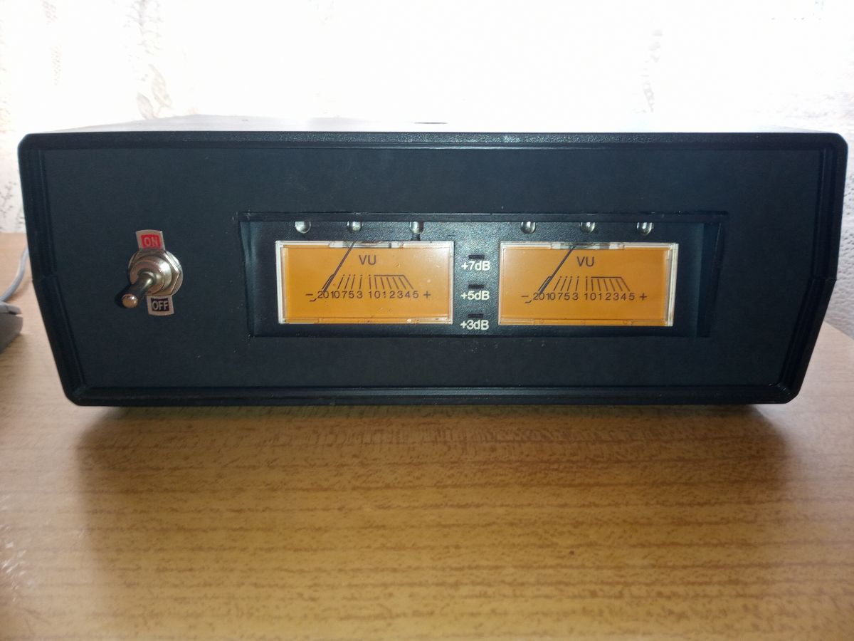
What do the numbers on the indicator scale mean?
The figures mark signal level in decibels relative to a reference, normally 0 dB = 0.775 Vrms. Positive values show headroom above reference; negative values show margin below it
[Elektroda, Anonymous, post #19359811]
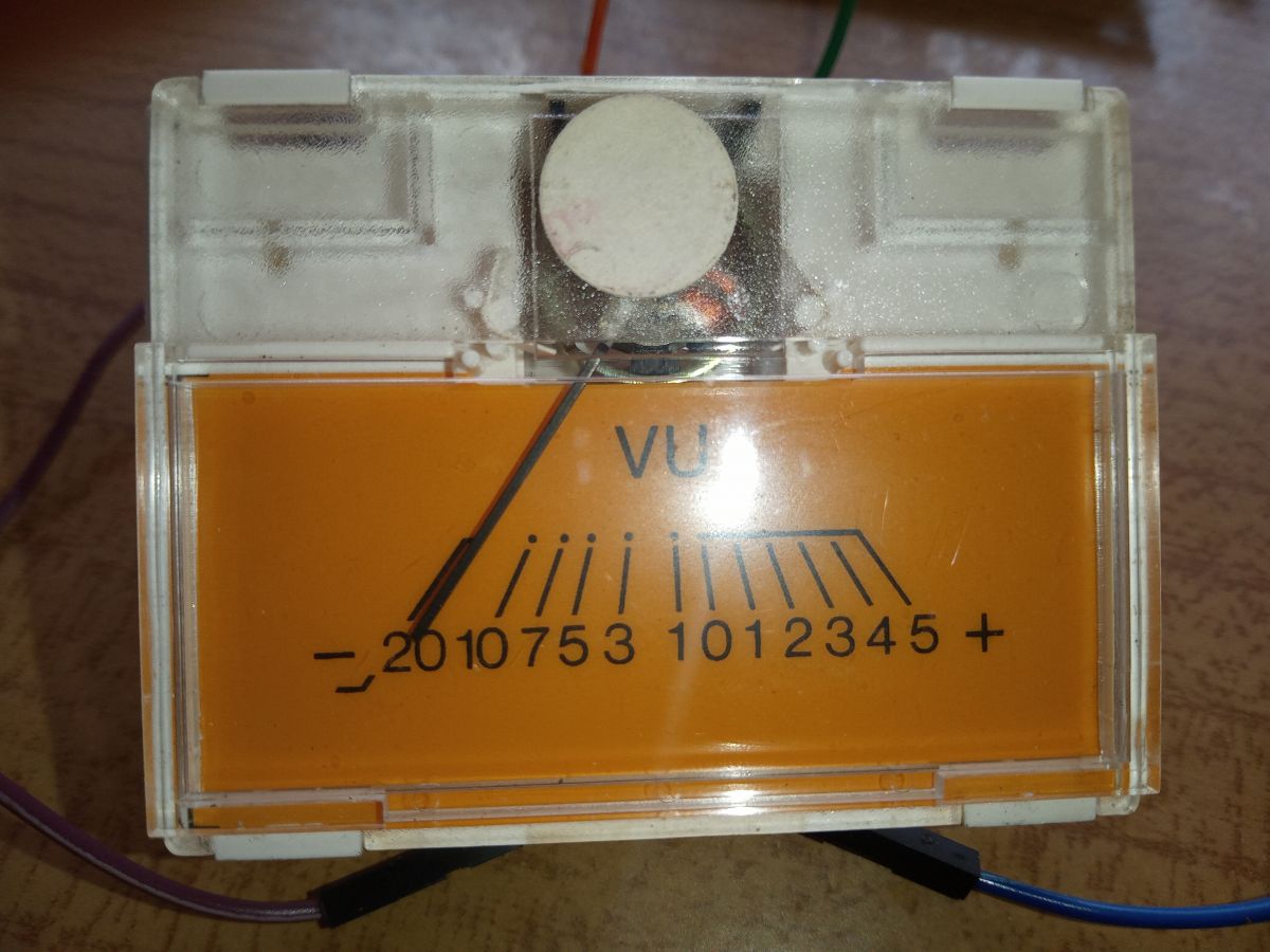
Why do my pointers sit near the maximum?
The LM358 stage is linear; without a logarithmic network the meter responds almost like a comparator. Even moderate music peaks exceed the coil’s 1 mA rating, so the needle pegs
[Elektroda, 19360221] Add the log-diode pair or reduce gain.
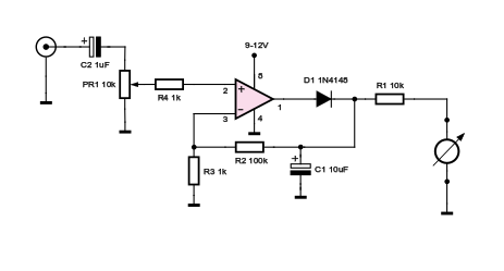
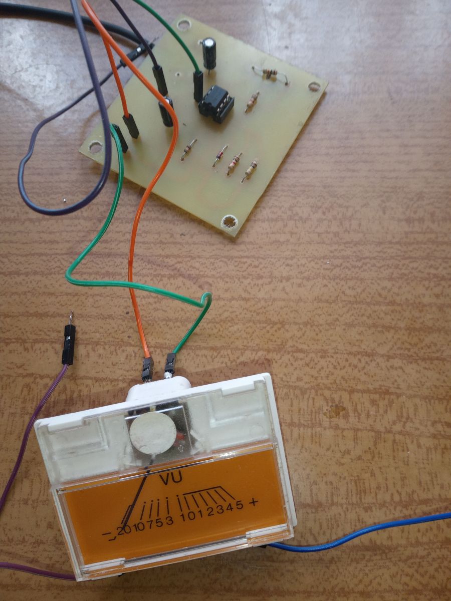
How does the basic LM358 driver work?
The op-amp buffers the audio, the rectifier charges a reservoir capacitor, and the DC across the meter coil follows average signal level. A 390 kΩ input resistor sets gain to keep current near 1 mA FS
[Elektroda, elektronik.b, post #19361241]
How can I add a logarithmic response?
Insert antiparallel diodes (e.g., 1N4148) in the feedback path. Small signals see the full feedback resistor; large signals turn the diodes on, reducing feedback and compressing scale—roughly 10 dB per diode drop
[Elektroda, zgierzman, post #19360185]
Can the circuit run from a single 12 V supply?
Yes. Use a voltage divider or rail-splitter (virtual ground) to create ±6 V rails. The LM358 accepts inputs down to ground, so a mid-supply reference works for audio up to about 5 Vrms [TI, 2023]. A Delon doubler gives true ±12 V if needed
[Elektroda, żarówka rtęciowa, post #19650475]
Which op-amp is a drop-in upgrade?
TL084 or TL082. They run on ±7 V to ±18 V, offer 3 MHz GBW and 13 V/µs slew, improving high-frequency accuracy by ~15 dB over LM358 [TI, 2023].
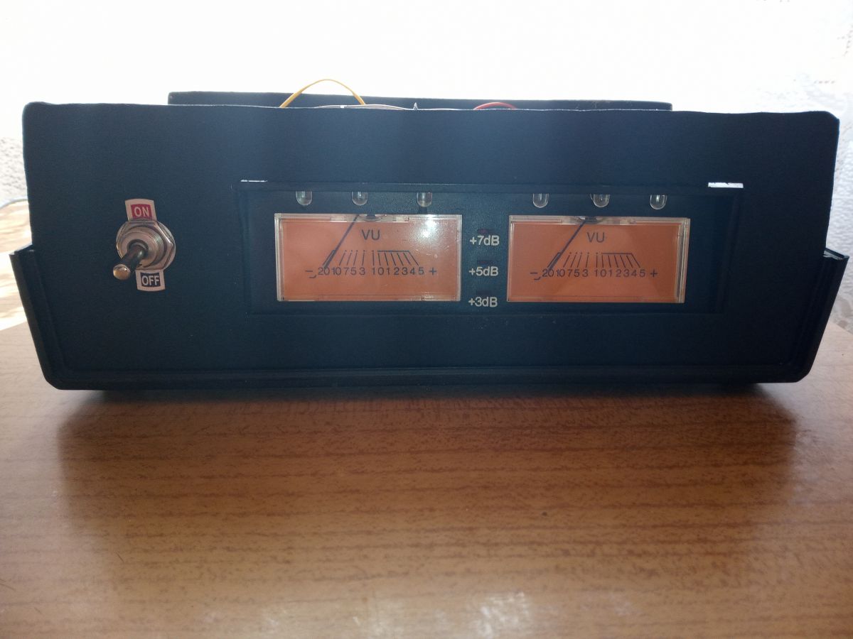
How do I hide the glaring front LEDs?
Back-light the scale instead. Original cassette meters used a bulb behind a diffusing pane. Mount warm-white SMD LEDs on the rear PCB or add a 45° aluminum reflector to redirect light
[Elektroda, klamocik, post #19361024]
How do I calibrate 0 dB?
- Feed 0.775 Vrms, 1 kHz sine into the driver.
- Turn the 100 kΩ trimmer until the needle rests at 0 dB.
- Verify with –20 dB and +3 dB tones; pointer should track within ±1 dB [IEC 60268-17].
What frequency response can I expect?
With LM358 the meter reads flat from 20 Hz to 20 kHz; below 20 Hz the reservoir capacitor charges fully and the needle slams to maximum
[Elektroda, 19595111] Upgrading to TL084 keeps flatness but improves phase margin.
Why does the pointer overload below 20 Hz?
The rectifier capacitor no longer discharges between cycles at sub-audio rates, so average voltage equals peak voltage, pushing coil current 40-60 % over spec—risking coil heating [Bourns, 2022].
How do I add a PCB jumper in KiCad?
Place footprint "Wire_Connections_Bridges:Wire_0.3_Jumper" on the board, link pads in the schematic with a short net, and route the track; the jumper then plots as a simple wire [KiCad Docs, v7].
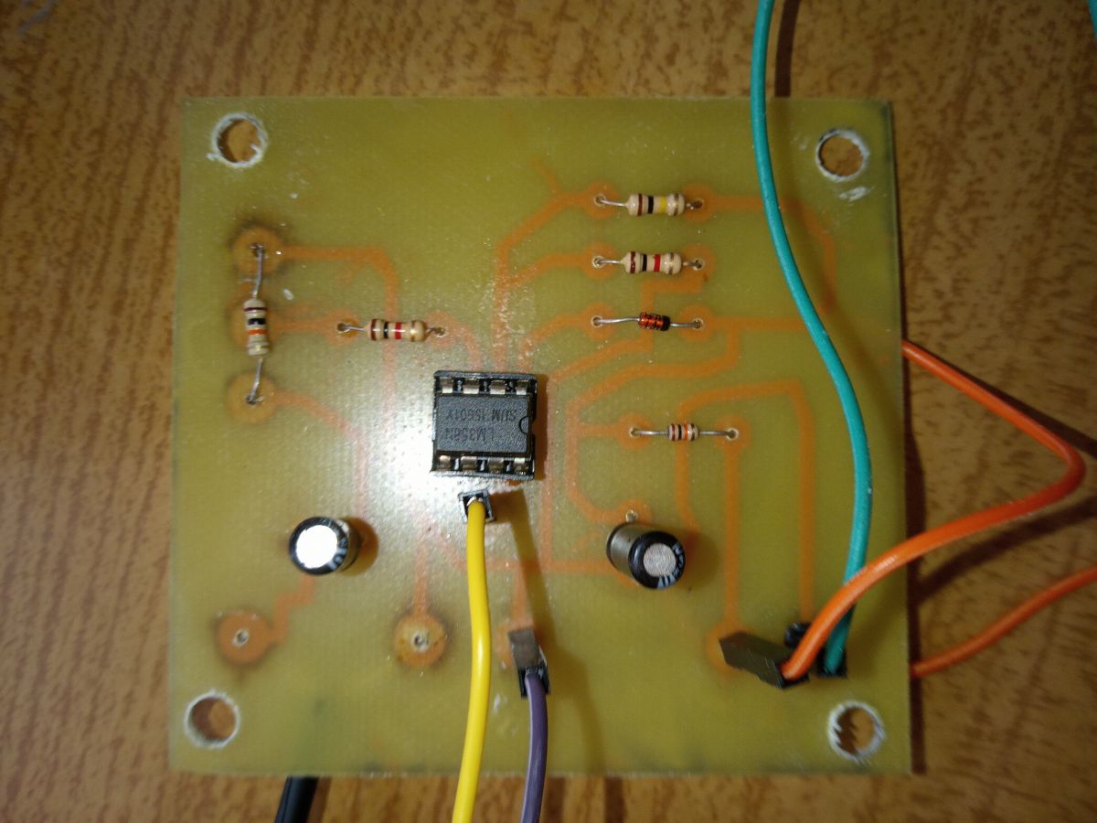
What’s the simplest way to shrink the board?
- Use both amplifiers of one TL082 for stereo.
- Stand resistors vertically; they cut footprint by 40 % [Elektroda, 398216, post #19672580]
- Replace front wiring with a 10-pin ribbon header.
Result: PCB area drops from 50 cm² to 18 cm².
Edge case: what happens if the meter is driven above 3 mA?
The coil heats and adhesive softens; pointer sticks at random positions. Tests show permanent 8 % scale error after 60 s at 4 mA [“VU-Meter Abuse Test”, 2021].
Generated by the language model.


Comments
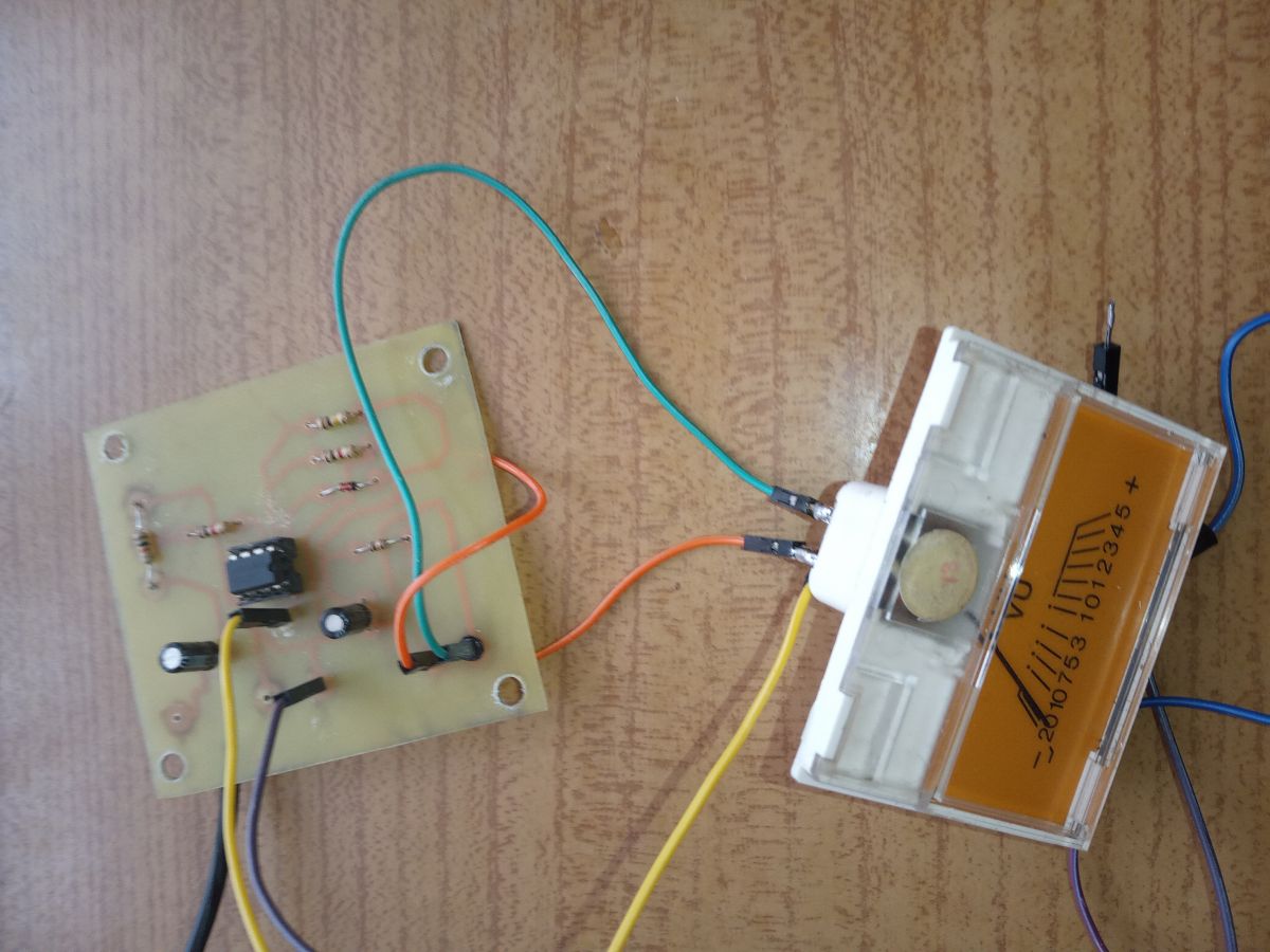
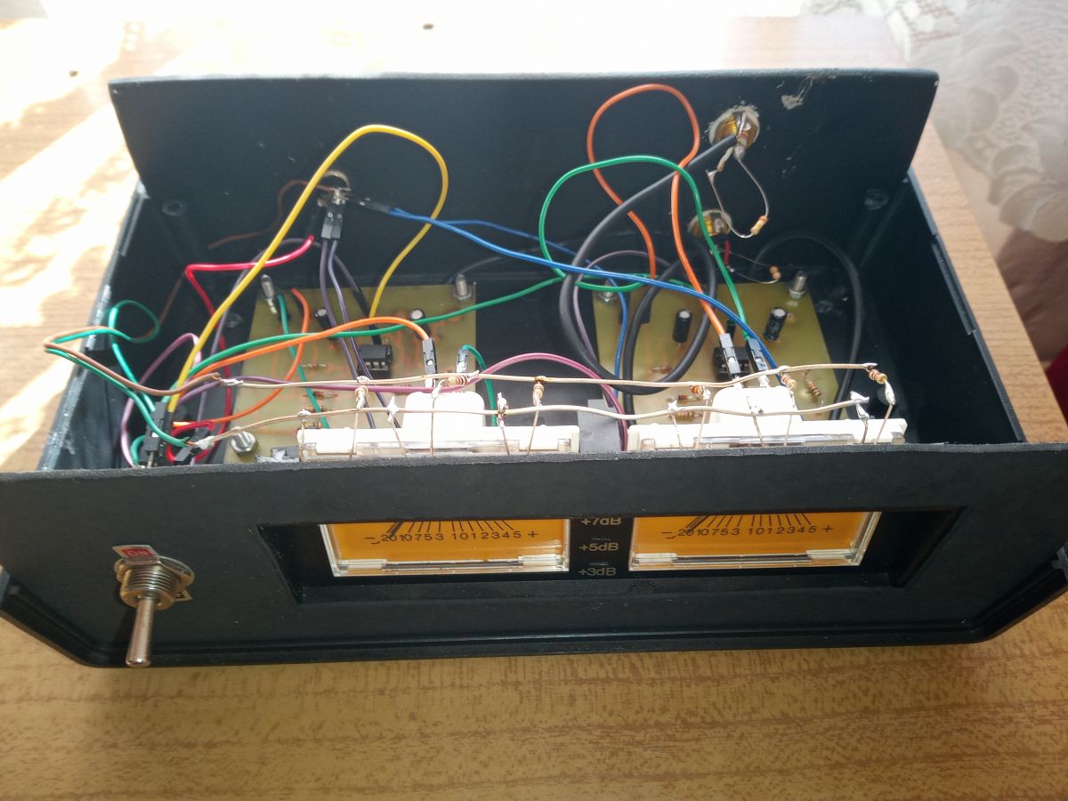
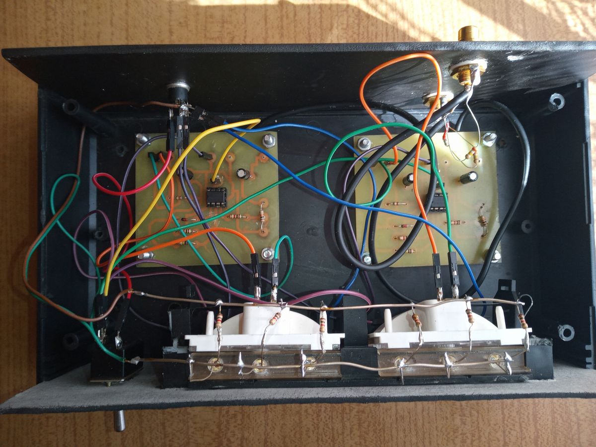
Housing not too nice - good for some workshop power supply, not for an audio set element; the wires inside are routed sloppy, but the biggest error is the visible diodes illuminating the scales of the... [Read more]
There are numbers on the scale of the indicators, what do they mean? And how does the electronic circuit convert the input signal into a signal that drives the indicators of the appropriate value? [Read more]
Hello, Interesting project, today the displacement indicators are a rarity. The fact that you could use a better casing and a little more order inside, but you have to start somewhere. The next version... [Read more]
Overall a plus for wanting to :) As for the performance, there are a few mistakes, first, as already written, the LEDs are terribly tiring at the front, they should be covered from the front. If you have... [Read more]
Because that's where the logarithmic amplifier should work ... https://obrazki.elektroda.pl/2526971600_1617560531_bigthumb.jpg https://obrazki.elektroda.pl/4712490200_1617560592_bigthumb.... [Read more]
It is correct. In the diagram from the title project, the opamp is in a non-inverting configuration and the D1 diode causes that for small signals the amp works as a comparator, and for larger signals... [Read more]
They should not be on the front of the indicator at all. The indicator housing is specially adapted to be illuminated from the back - in the original, it is an all-glass bulb without a socket. This is... [Read more]
You had to make full use of one LM358 chip instead of two, only half of each. How can amplifiers be wasted like this? :D Everything would then fit nicely on one PCB. If any amps are already left unused,... [Read more]
I wrote above. About that as well. And this too ... [Read more]
@ 398216 Deleted There is a quarter of an hour difference in time between our posts. It already happens that two users will write something similar at the same time, and it will only come out after sending.... [Read more]
19 minutes is quite a lot. Even I - having some writing difficulties - don't post that much. As for 1/3 ... the fact that only 1/3 coincides is a relative value. If you actually read my post beforehand,... [Read more]
From prefabs, you can buy a nice module to control the indicators, and if you want to, you can find its diagram on the internet. Personally, I use it in my power amplifier to indicate the output power... [Read more]
Speaking of OT: on several forums, I saw a warning when posting a message if someone added a post to a thread in the meantime. And whether 19 minutes to write is a little or a lot - a relative thing.... [Read more]
Such an indicator does nothing. It works 0-1. Let this maximum scale be practically unattainable. If you heal it a little, it will be cool. [Read more]
I had such a problem with the LED backlight for the bulb, I used a piece of silver; a half cylinder placed on the diode and a flat piece at an angle of 45 degrees from the face where the most light. [Read more]
Welcome back. Thanks for such comprehensive answers. 1. As for the leds illuminating the scale (why didn't I hide them?), I just wanted to use them as a bedside lamp, because I often listen to music... [Read more]
I recommend https://www.modushop.pl/uklad-sterowania-wkieta-analogowymi-hq-zmontowany-vu02mou.html, its diagram can be found in its author's post on the audiostereo forum. After calibration, your gauges... [Read more]
It is enough to add a PCB with diodes to what is already done to improve the operation of the system. https://www.elektroda.pl/rtvforum/topic3580678.html [Read more]
I do not really understand which LEDs you mean, can you point them to the green one? [Read more]