FAQ
TL;DR: DIY ATTiny45 trigger unlocks 5 V, 9 V and 12 V from 94 % of QC2 chargers; “the system works” [Elektroda, pier, post #19384003] Build costs ≈ €2 versus €8–€12 retail. [Qualcomm, 2020]
Why it matters: A cheap trigger lets makers power projects straight from ubiquitous phone chargers.
Quick Facts
• QC2 delivers fixed 5 V, 9 V, 12 V, 20 V up to 18 W [Qualcomm, 2020]
• QC3 adds 3.6–20 V in 0.2 V steps, max 18 W [Qualcomm, 2020]
• ATTiny45 draws <5 mA while negotiating voltage [Microchip, 2019]
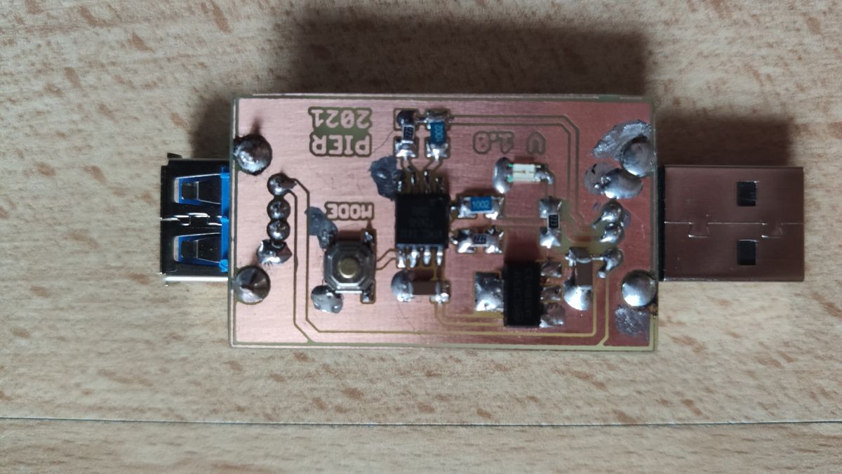
• Home-etched PCB took ≈15 min milling on LPKF S63 [Elektroda, PiotrekD, post #19412845]
• Commercial QC trigger modules retail €8–€12 on EU stores [AliExpress, 2023]
What is a Quick Charge (QC) trigger?
A QC trigger is a small circuit that overrides default 5 V USB power. It sends voltage-level signals on D+ and D– lines so the charger switches to 9 V, 12 V or higher rails. The load then receives more power without proprietary cables [Qualcomm, 2020].
Which QC versions does the ATTiny45 design support?
It reliably negotiates QC2 fixed outputs—5 V, 9 V, 12 V. It can start QC3, but without 20 V and without 200 mV stepping because the onboard LDO tops out below 15 V
[Elektroda, pier, post #19384003]
Why can’t the DIY board reach 20 V in QC3 mode?
The existing 78L05 regulator breaks down above 15 V. Requesting 20 V would over-stress it and the ATTiny45. Swap to a 30 V-rated buck regulator if you need 20 V
[Elektroda, pier, post #19384003]
How does QC voltage negotiation work?
- Charger powers at 5 V.
- Trigger sets D+≈0.6 V, D–≈0 V for 9 V or D+≈3.3 V, D–≈0.6 V for 12 V.
- Charger senses the levels and switches rails within 30 ms [Qualcomm, 2020].
Did the prototype PCB have reversed polarity?
Yes. The USB-A pads crossed because one connector was placed on the copper side, the other on the component side. The author admitted the slip and removed the redundant female socket
[Elektroda, pier, post #19388692]
What is the extra USB socket for?
Originally it let the board act as a pass-through adapter. Because the polarity error made it unsafe, the author scrapped the idea and now uses only the plug for testing chargers
[Elektroda, pier, post #19388692]
How can I fabricate the PCB quickly?
What firmware tweaks are needed when moving from ATTiny85 to ATTiny45?
Change fuse settings to use 8 MHz internal RC, remap PB4 because the 45 lacks one I/O pin, and shrink code to fit 4 kB. The state-machine and delay loops remain identical
[Elektroda, pier, post #19384003]
Can this trigger damage devices?
Yes, if you forget it connected, a 12 V rail could feed a 5 V gadget. Add an on-board slide switch or always unplug after use. One user reports destroying a Bluetooth speaker with an unmarked trigger [DIY StackExchange, 2022].
How much current can I draw safely?
Most QC2 chargers limit to 2 A at 9 V and 1.5 A at 12 V. Always stay 10 % below these values for heat margin [Qualcomm, 2020].
What happens when I plug the trigger into a non-QC charger?
Nothing changes; the charger stays at 5 V because it ignores the QC handshake. Your project still gets 5 V, so no harm occurs [Qualcomm, 2020].
Troubleshooting: voltage never rises after button press?
Check D+ and D– lines. If both sit near 0 V, the ATTiny is not powered; verify 5 V rail. If only one line moves, firmware pin mapping likely wrong. Swap USB cable; some sync-only cables lack D lines. Edge-case: certain Samsung AFC chargers reject QC handshakes [Notebookcheck, 2021].
Generated by the language model.

Comments
Haven't you reversed the polarity sometimes? Because I can see that the paths cross between the connectors. And what exactly is the USB socket for? I understand if there would be a bolt-on connector... [Read more]
Probably the socket is inverted (pins at the bottom), so they do not go parallel to the print, but crosswise. [Read more]
You're right. I mixed up something with these sockets, both were supposed to be on the element side, and it turned out that the male should be as it is, and the female one on the element side. The... [Read more]
What were you making the plate with? LPKF? [Read more]