Elektroda.com
Elektroda.com
X
This content has been translated flag-pl » flag-en View the original version here.
  • Quick Charge trigger - quick project
    Hello

    Somehow recently after mounting to mine powerbank the Quick Charge module, I wanted a trigger for such devices. As I did not smile to spend PLN 40 on such a crap and I did not have more sense than the desire to have it, I decided to do something with the litter. There was another reason for self-construction - a lot of free time, because of this situation, most of them probably have too much time, and the weather is what everyone can see.
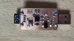
    Quick Charge trigger - quick project

    I found ready , simple and in total it triggers only QC2 correctly because QC3 has the ability to adjust the voltage every 200mV. QC3 will also release, but without 20V voltage, because for this you would have to change the stabilizer, and there will be no regulation every 200mV. In relation to the original, I changed the processor to the attiny45, because I had one. The system works and can be used to check our charger, or if we forget, we can damage some equipment connected to this system.

    Cool? Ranking DIY
    Do you have a problem with Arduino? Ask question. Visit our forum Arduino.
    About Author
    pier
    Level 24  
    Offline 
    pier wrote 2236 posts with rating 1735, helped 39 times. Live in city BiƂgoraj. Been with us since 2006 year.
  • #2
    piotr_go
    DIY electronics designer
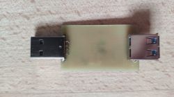
    Haven't you reversed the polarity sometimes? Because I can see that the paths cross between the connectors.
    And what exactly is the USB socket for? I understand if there would be a bolt-on connector or something.
  • #3
    popej
    Level 13  
    Probably the socket is inverted (pins at the bottom), so they do not go parallel to the print, but crosswise.
  • #4
    pier
    Level 24  
    piotr_go wrote:
    Haven't you reversed the polarity sometimes? Because I can see that the paths cross between the connectors.
    And what exactly is the USB socket for? I understand if there would be a bolt-on connector or something.

    You're right. I mixed up something with these sockets, both were supposed to be on the element side, and it turned out that the male should be as it is, and the female one on the element side. The starting point was completely dismissed, because, as you rightly pointed out, it is redundant.
    All in all, the layout was created out of boredom as a curiosity and a desire to know how these QC standards work.
  • #5
    PiotrekD
    Level 13  
    What were you making the plate with? LPKF?