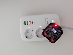
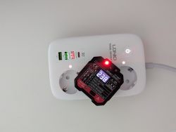
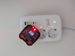
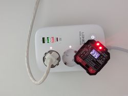
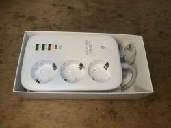
 Today I will present the interior and firmware change of a strip/extender offering three power sockets and four USB sockets, in addition with QC support. I will upload open source software onto the product OBK so that it works 100% locally, in a way that is secure and respects the user's privacy, without the cloud.
Purchase LDNIO SEW3452 USB QC
This strip is available to buy in many shops, usually for a little more than 100 zł:
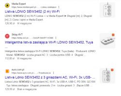
Parameters by. Seller:
Quote:
Manufacturer: LDNIO
Model: SEW3452
Number of AC outlets: 3
Number of USB ports: 4
Cable length: 2m
Power rating: 2500W
Input: 100-250V 50/60Hz 10A (max.)
PD output: 5V/3A, 9V/3A, 12V/2.5A, 15V/2A, 5A 30W (max.)
PPS output: 3.3-5.9V/3A, 3.3V-11V/3A
QC output: 5V/3A, 9V/2A, 12V/1.5A 18W (max.)
Auto-ID output: 5V/2.4A
Power output: 30W (max.)
Wireless connectivity: WiFi 2.4 GHz
Colour: White
Application: Tuya Smart
Dimensions: 15.6 x 10.3 x 4 cm
Gross weight: 535g
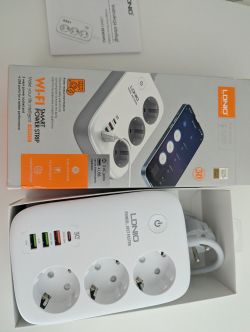
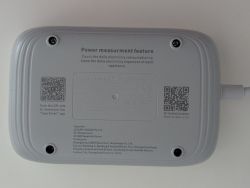
What you get in practice:
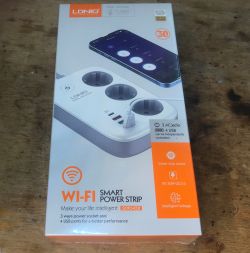
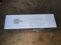
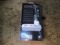
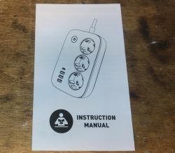
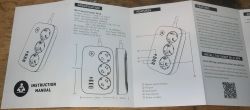
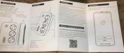
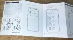
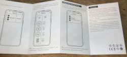
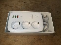 Instruction:
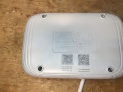
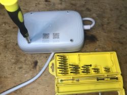
Interior of the LDNIO SEW3452 USB QC This will be a bit tricky. You need a special screwdriver with a triangular tip.
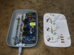
The interior is really rich. I can even see some coil and filters, although there is an empty space for a varistor?
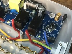
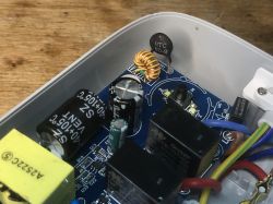 There is also an NTC thermistor, probably limits the inrush current.
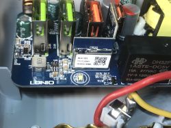
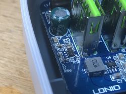
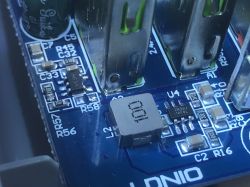
The WiFi module is a CB2S (BK7231N). You can see the step down converter next to it (element U4 with large coil L2). The relay is for 5V, 1ASTE-DC5V.
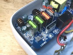
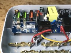
You can see the A63A circuit:
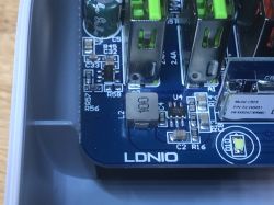
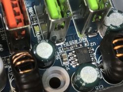
The intermediate inverter is based on NDP1335KC:


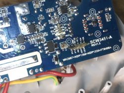
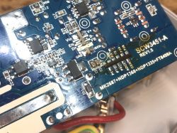
PCB designation: SCW3451-A REV1.5
MK2687+NDP1360+NDP1335+FT8498A
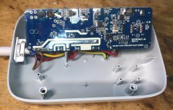
On the underside I also see an NDP7912KC and I think some kind of optocoupler.
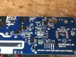
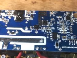
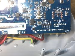
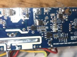
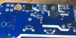
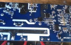
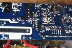
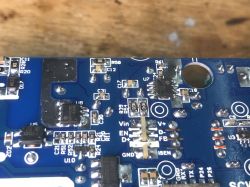 NDP7912KC is a synchronous rectifier, not bad, it's more efficient than a Schottky diode:

Another inverter seen on the bottom is the NDP1360:
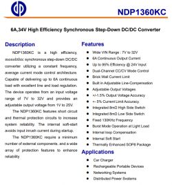
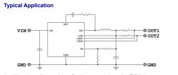
The flyback converter controller itself here is an MK2687:

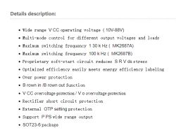
[b] Current capacity test of the LDNIO SEW3452 USB QC
I wanted to test the current capacity of this strip, but I did not have a suitable artificial load. I therefore used two loads at once - LD25 and LD35.
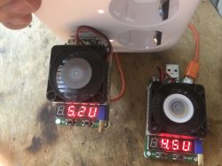
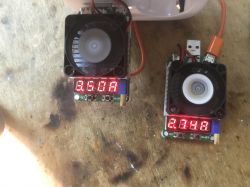
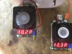
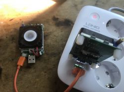 Let's add up the currents - 3.5A + 2.74A,
Power: 18.2W + 12.3W. That is, a total of 31W.
Then the protection is switched on.
I also checked the QC with my Xiaomi phone:
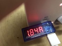
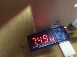
Truly, it switches on 7.5V and 1.5A.
However, not every port has QC:
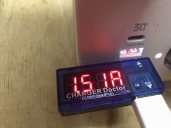
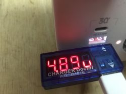
Changing the QC USB firmware LDNIO SEW3452 In the middle is CB2S, or BK7231. You can upload OpenBeken:
https://github.com/openshwprojects/OpenBK7231T_App
According to the flasher instructions:
https://github.com/openshwprojects/BK7231GUIFlashTool
And our tutorials on YT:
https://www.youtube.com/playlist?list=PLzbXEc2ebpH0CZDbczAXT94BuSGrd_GoM
CB2S is best soldered out. I soldered it out straight away, I didn't test the programming in the circuit. After all, all you need is a bit of braid, flux and you're done.
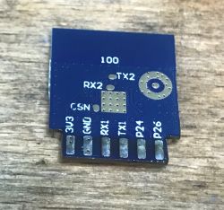
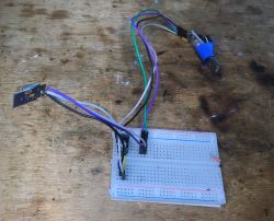
My flashing circuit (USB to UART converter and LDO 3.3V):
After reading the 2MB firmware my flasher correctly decodes the Tuya configuration partition, so we know the GPIO roles. There is no need, as with Tasmota, to guess what is on which pin. Everything is given like on a tray:

Tuya configuration:
Code: JSON
Word description:
Device seems to be using CB2S module, which is BK7231N chip.
- Relay (channel 1) on P6
- Relay (channel 2) on P7
- Relay (channel 3) on P8
- Relay (channel 4) on P26
- WiFi LED on P23
- Pair/Toggle All Pin on P24
The fourth relay controls the USB outputs.
OpenBeken template:
Code: JSON
The template can be added according to the instructions from here:
After uploading, everything works as expected.
Summary Quite a nice strip, and even future-proof - without QC it's already like being without a hand. The electronics inside itself are quite complex and you don't see too much cost cutting, this is no longer a simple USB "charger" power supply, there are several inverters, there is PD control and they even gave a synchronous rectifier instead of a Schottky diode at the output of the first stage (flyback converter). In addition, the product can be converted to work locally and with Home Assistant, so there are no privacy concerns. Just solder out the WiFi module and upload the firmware , no problem with GPIO configuration, my flasher reads everything automatically.[/b]
Cool? Ranking DIY Helpful post? Buy me a coffee.


