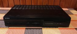
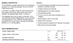
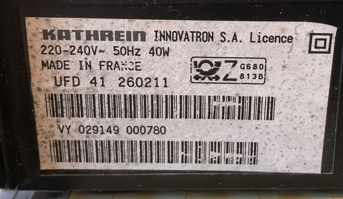
Here I will present short teardown of an old sat tuner Kathrein, model Innovatron UFD 41 260211 and then I will try to show the operation of some more interesting parts from inside and discuss their use in DIY projects. I will try to get running here, among others, RF modulator (ALPS), the A/V switch TDA8440 (used to switch between two PAL signals) and the RGB to PAL MC1377 converter. I will also look at the (standard) switching power supply from the inside.
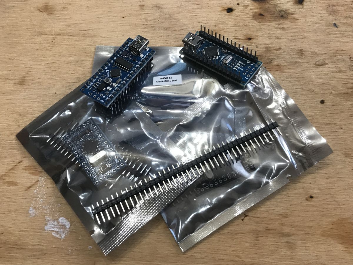
I'm going to use an Arduino Nano for the sake of the presentation.
Tuner Kathrein Innovatron
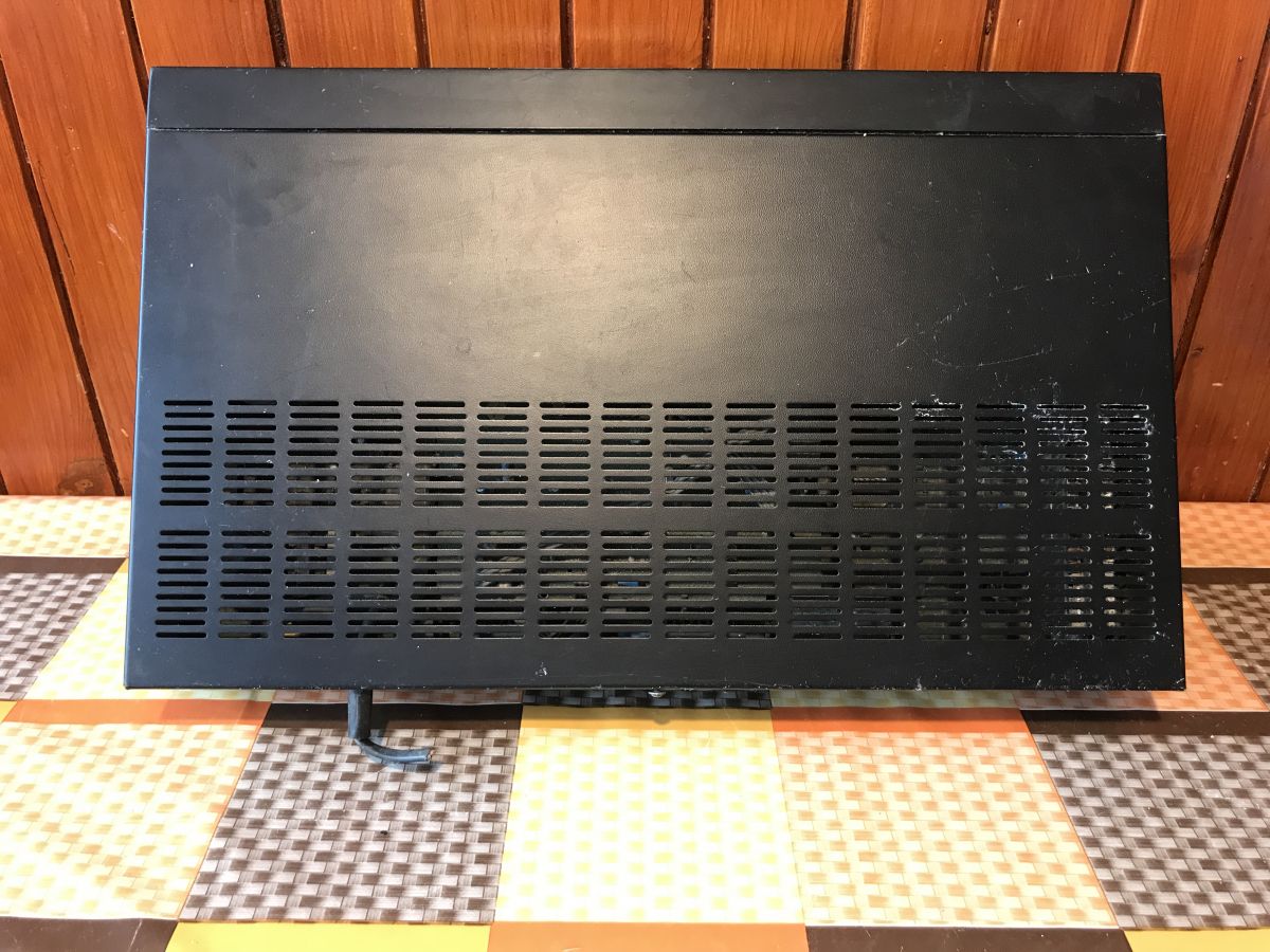
I've scored this little tuner in a very bad condition. We can clearly see it after removing the casing.
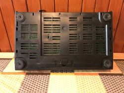
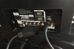
On the back we have a lot of connectors, two SCART (input and output), TV antenna input and its output (and channel adjustment from 40 to 49 for the modulated signal), stereo speaker connectors, S-VHS connector and of course also a connector for satellite signal.
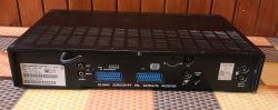
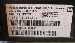
On the case, there is information about the supported standard - D2MAC eurocrypt pal satellite receiver.
D2-MAC is a satellite TV signal transmission standard, improved by the D-MAC version, whose bandwidth is about half that of D1-MAC, and the bandwidth is 10.125 Mbit/s.
The tuner cable is cut, which means that the previous owner did not plan to use it anymore.
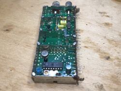
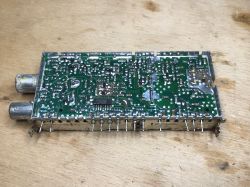
Bottom and top:

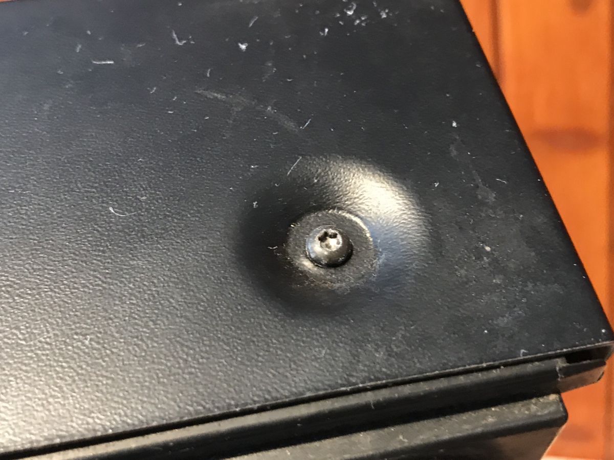
You will need a Torx screwdriver to get inside:
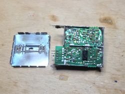
 First look inside
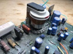
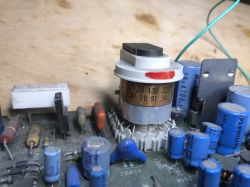
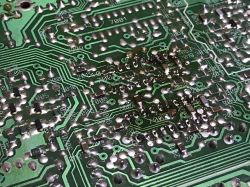
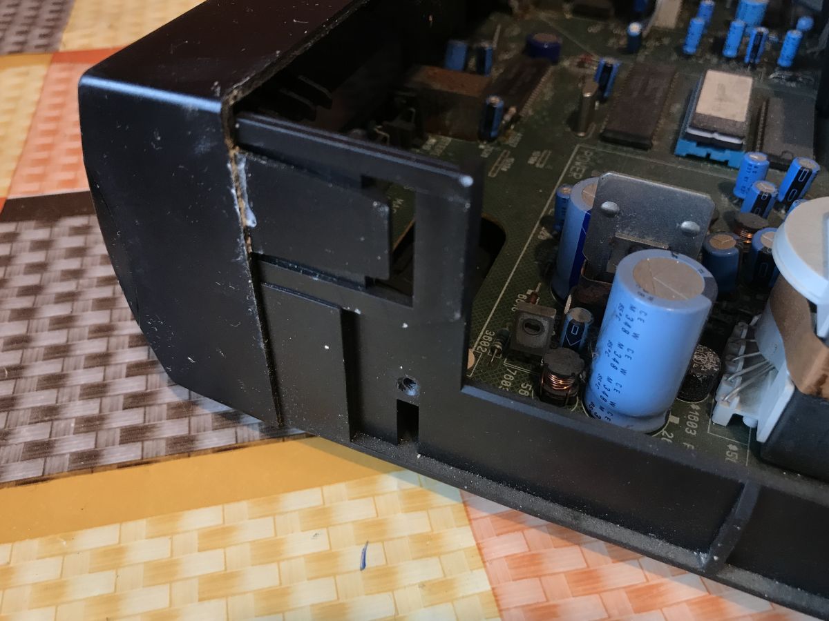
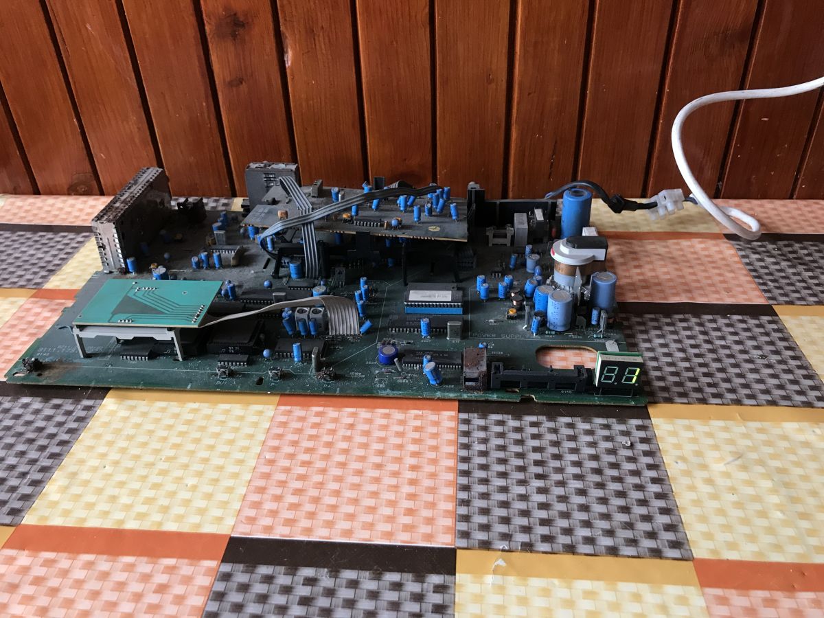
After opening the case, we can see a very bad condition of the hardware and electronics:
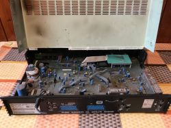
The front panel is held only by the hooks:

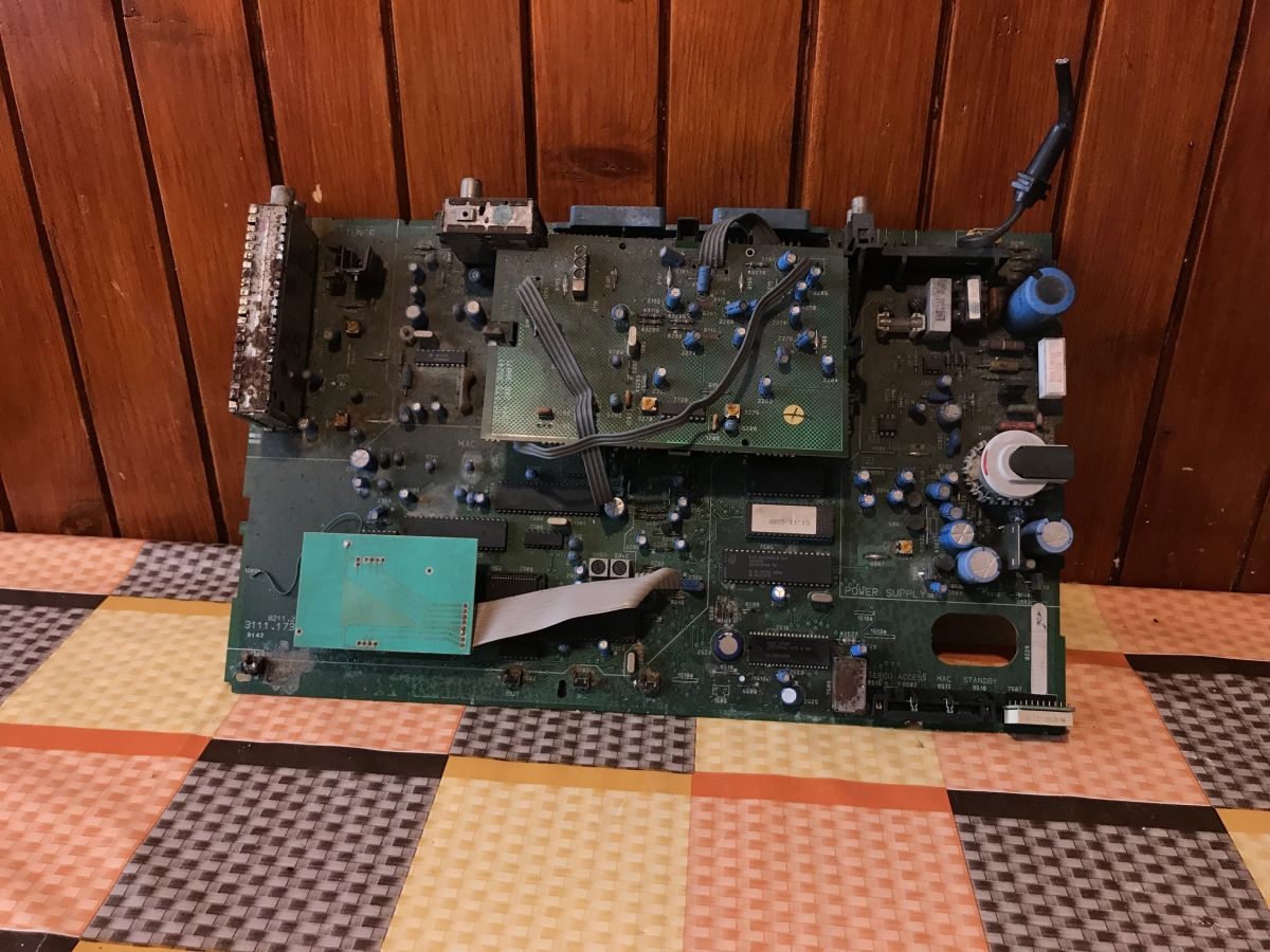
You can easily remove the PCB:

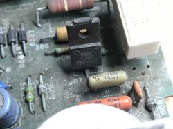
The equipment shows signs of life:

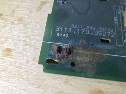
However, the corrosion was so advanced that the tactile switch itself escaped from the PCB:
Can anything inside still work and be useful?
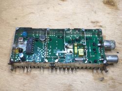
Quick overview of PCBs and ICs from inside
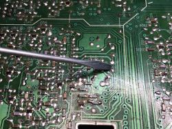
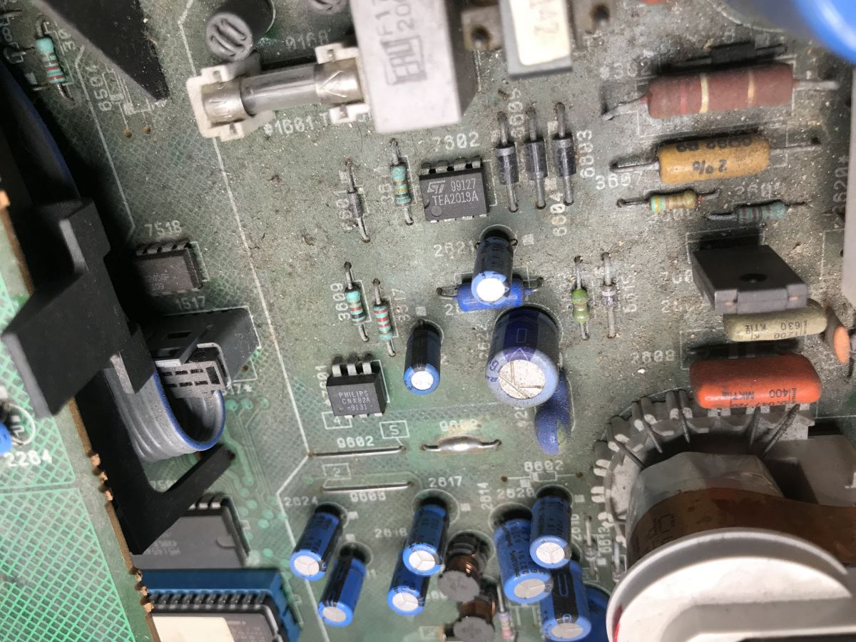
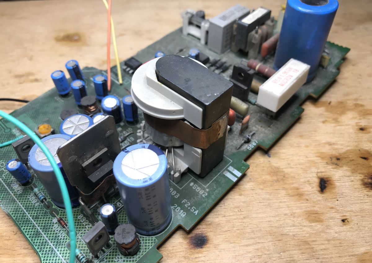
Let's look at the plate. PSU section:
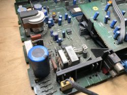
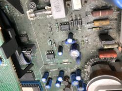
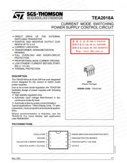
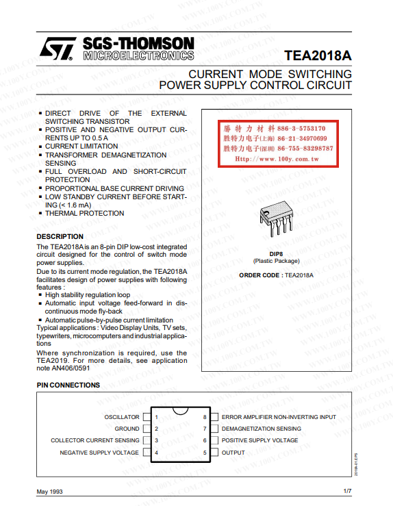
The power supply is based on TEA2018A.
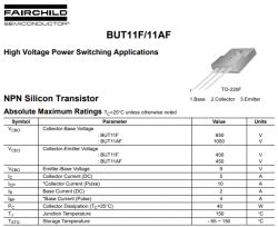
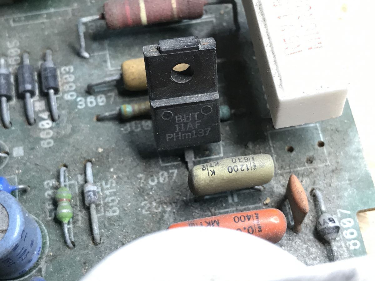
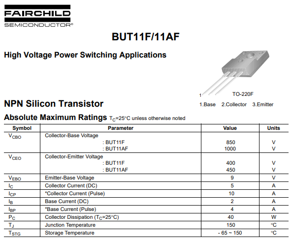
Switching is done on one NPN transistor (flyback topology), BUT11AF.
Feedback is taken from the secondary side through the CNX72A optocoupler:
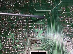
 In addition to the power supply, there are quite a lot of circuits here. I will try to briefly mention most of them.
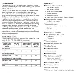
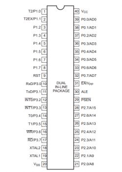
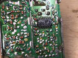
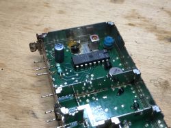
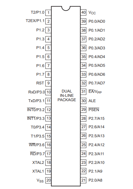
The 80C31 immediately caught my eye (along with the memory next to it):
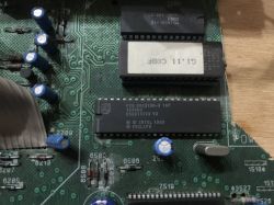
80C31BH-3 16P Intel 1980 Philips, 8-bit microcontroller, described as "128/256 byte RAM ROMless low voltage (2.7 V–5.5 V), 33 MHz". ROMless because the ROM is next door.
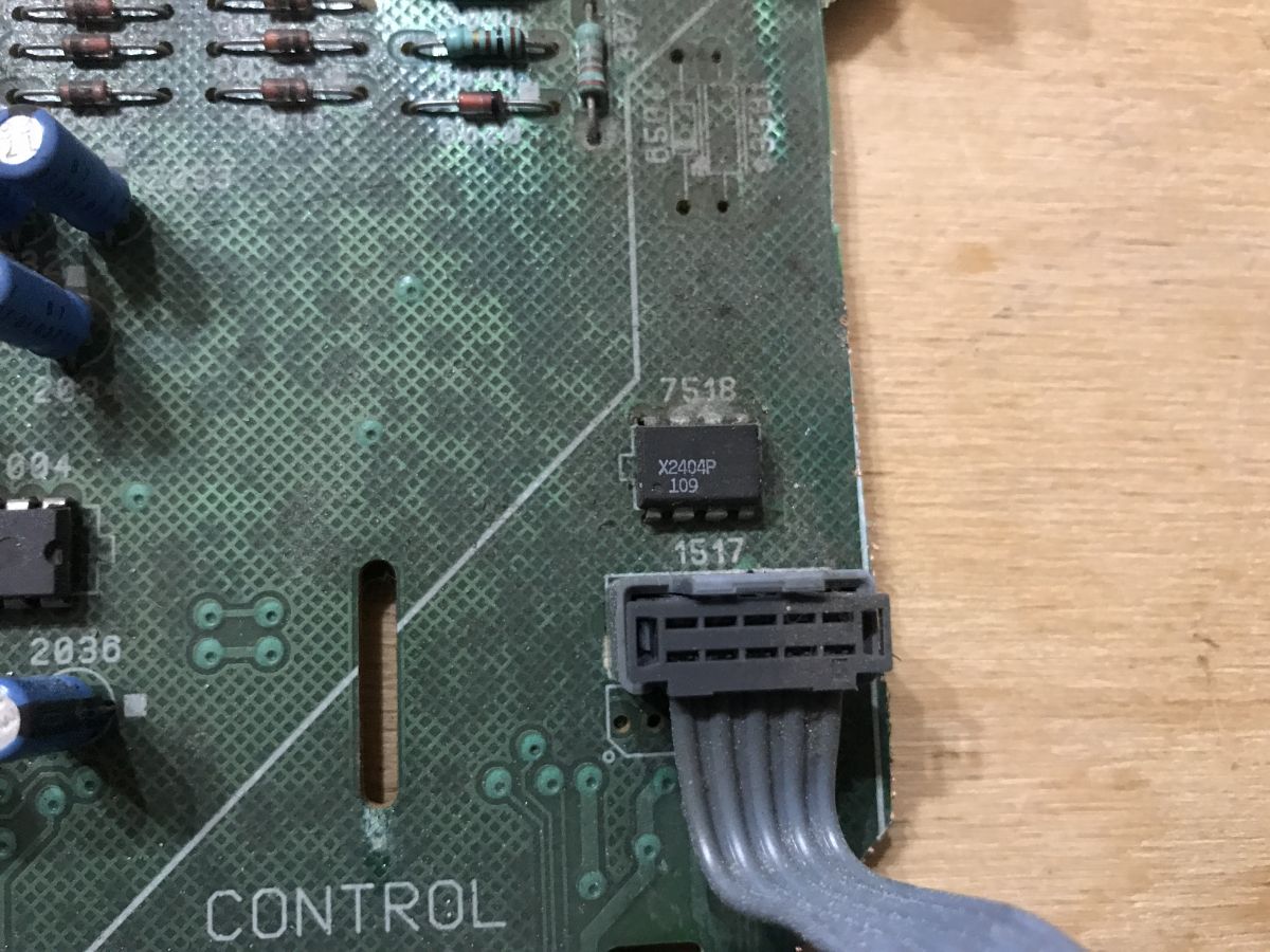
Of course, there is more memory on the board, there is also a typically small EEPROM for I2C:
X2404P, NMOS digital IC, 4 Kbit.
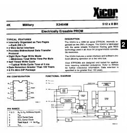
The note itself, as you can see, is quite old, and yet the pinout is consistent with what is now on sale (although instead of WP we have a Test pin).
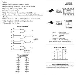
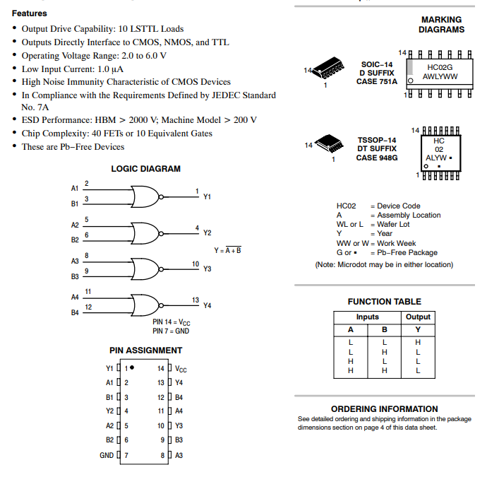
There are also a lot of 74HC series chips, e.g. two PC74HC02T:
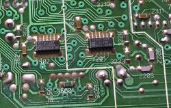
74HC02, i.e. NOR gates made in CMOS technology:
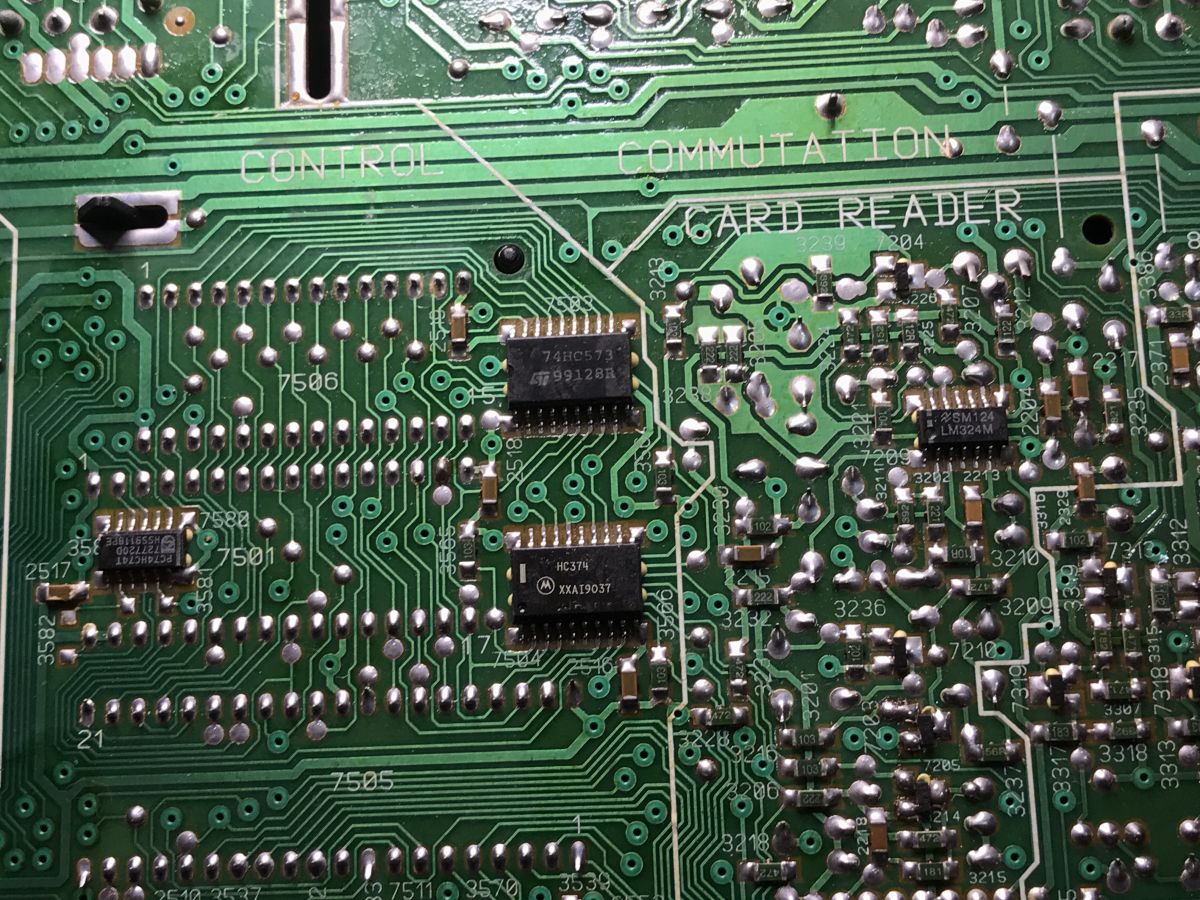
Subsequent layouts:
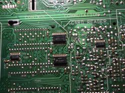
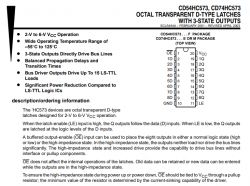
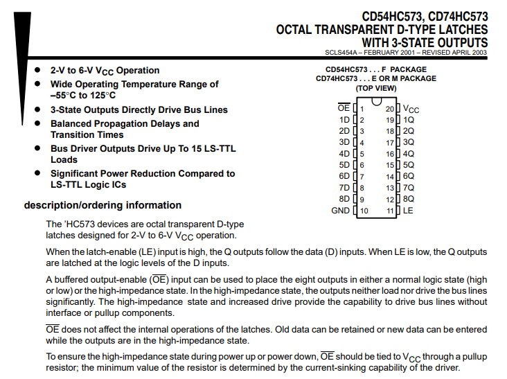
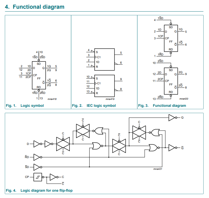
74HC573, in SO20, i.e. 8 D flip-flops with 3-state output:
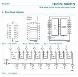
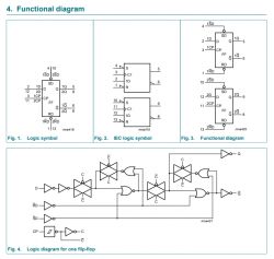
Next to it is HC374, also SO20, also a D-type flip-flop:
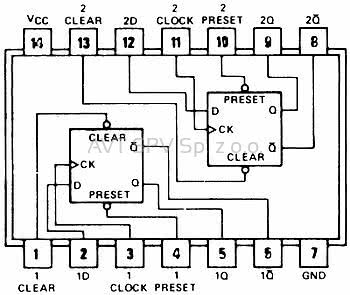
Then PC74HC74T, another flip-flop, more precisely 2 D-type flip-flops:

And LM324, an operational amplifier, more precisely 4 in one housing:
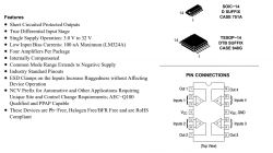
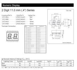
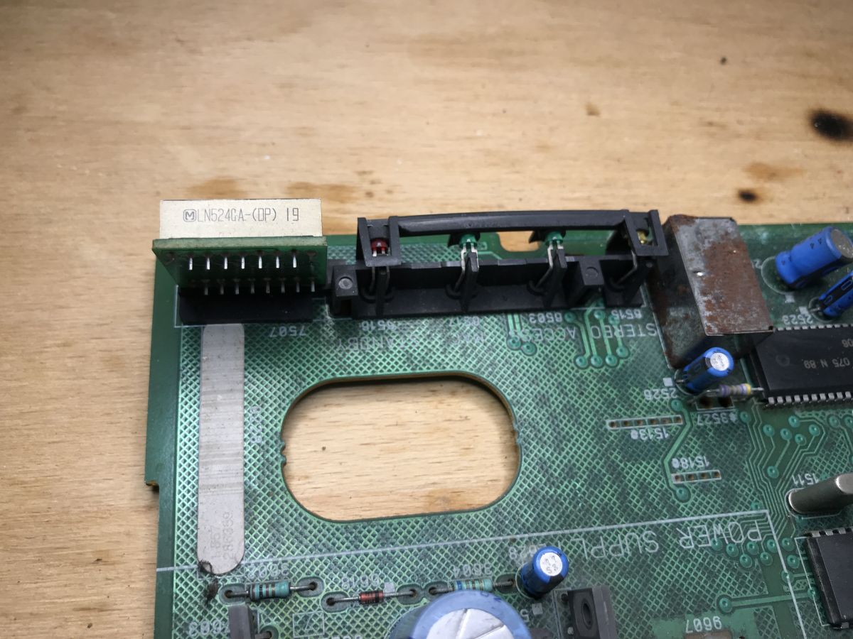
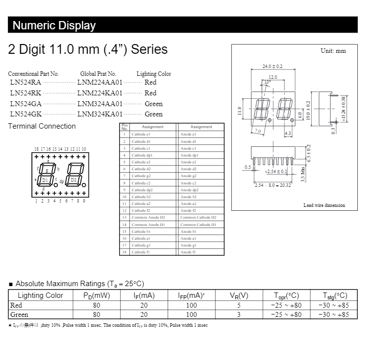
Two-digit 7-segment display LN524GA-(DP), DP in the name means dot point, i.e. a display with a dot:
Next we have some more chips dedicated to video processing:

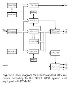
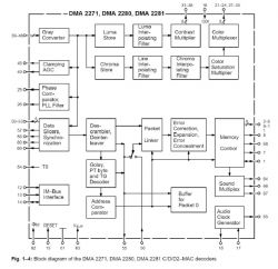
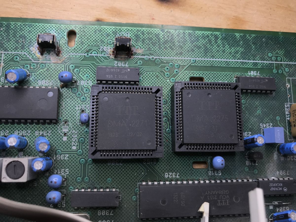
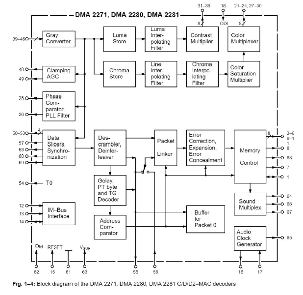
DMA2271 and DMA2275 are part of the DIGIT2000 system. This system decoded the signal in the C/D/D2-MAC standards to RGB. Below is a simplified block diagram of the decoder:
The internal diagram of the DMA2271 itself:
The RGB itself generated by this system is further processed and converted to PAL (or NTSC) on MC1377 (I will devote a separate paragraph to it):
There are also other FM systems in the area:
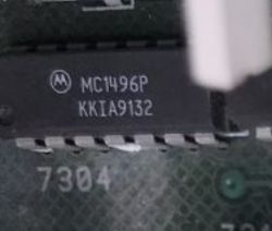
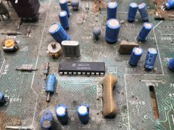
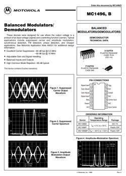
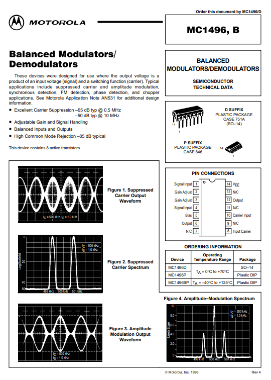
MC1496P, balanced modulator/demodulator in DIP14 package:
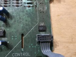
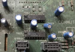
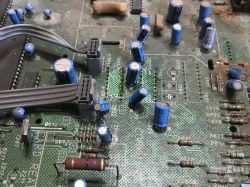
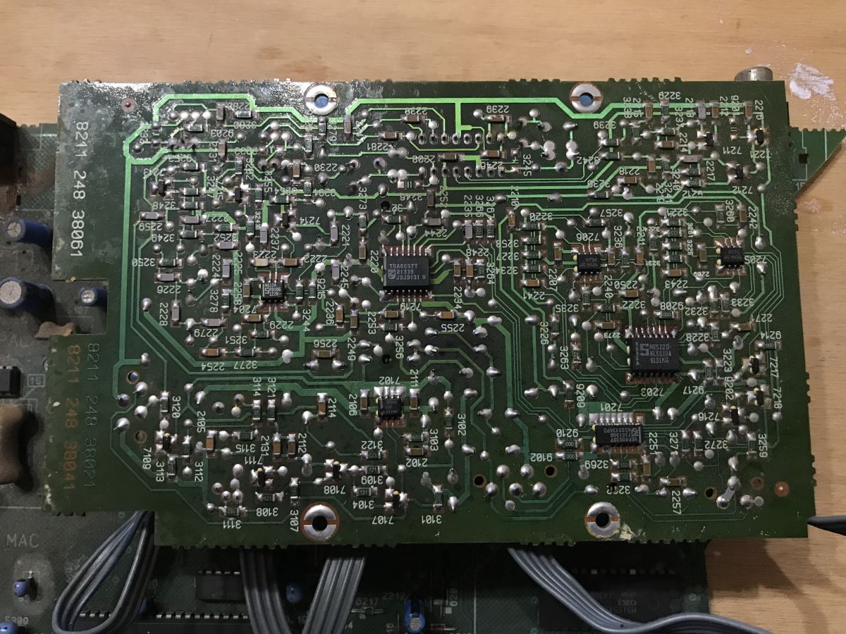
 Second PCB:
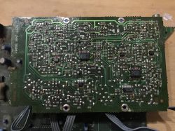
Here you can see:
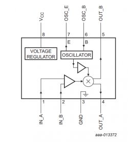
- NE612 (equivalent to SA612, radio signal processing system, consists of an oscillator and a mixer)
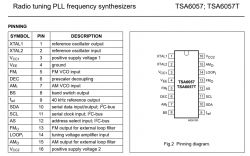
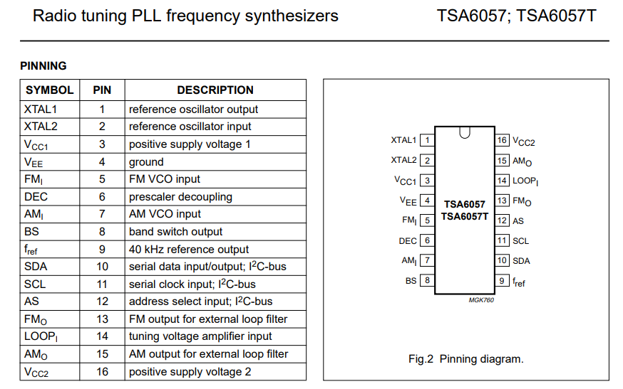
- TSA6057 (frequency synthesis system from PLL to I2C)
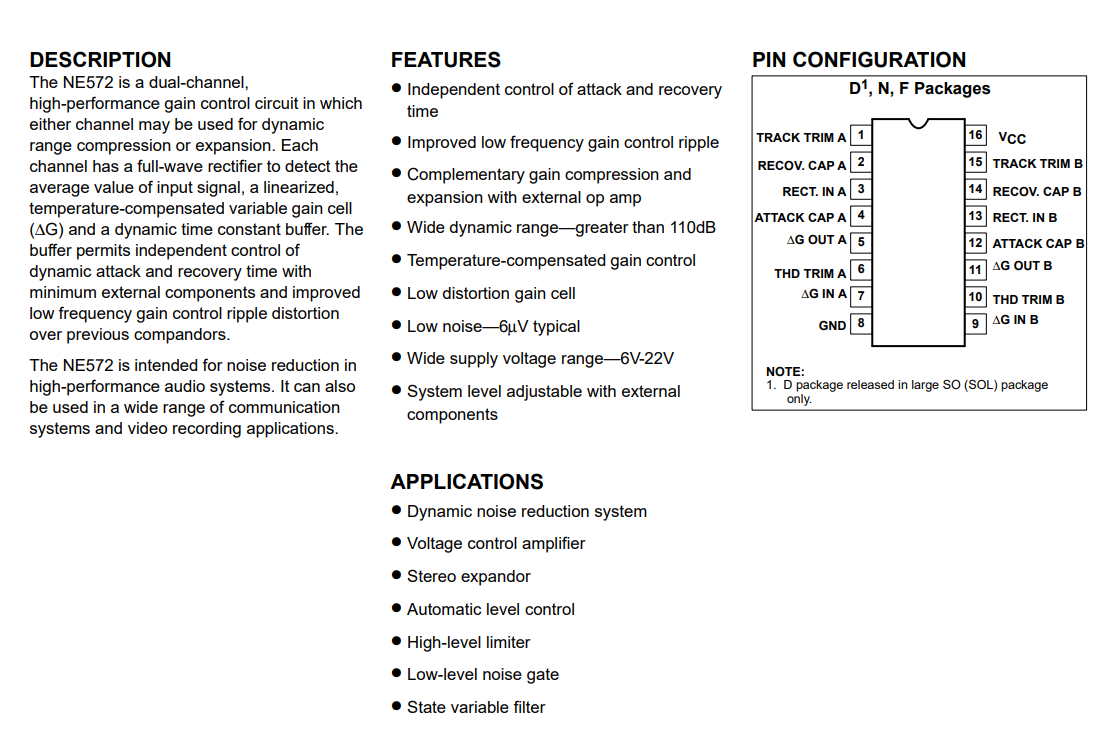
- NE572 (electronic gain control system, two-channel)

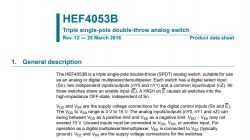
- HEF4053 (analog SPDT switch)
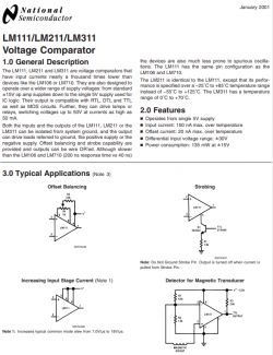
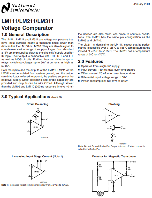
- LM311M (voltage comparator)
I think that's enough - there are still some undiscussed elements on the PCB, but they are rather less interesting than these.
Reusing the power supply
The power supply (as in many other cases) can be very easily separated and simply cut out of the motherboard. You have to be careful not to short-circuit and damage the necessary paths, but the power supply module obtained in this way can be fully functional. It is worth, however, before starting to load at least to a small extent the output of the converter with a resistor.

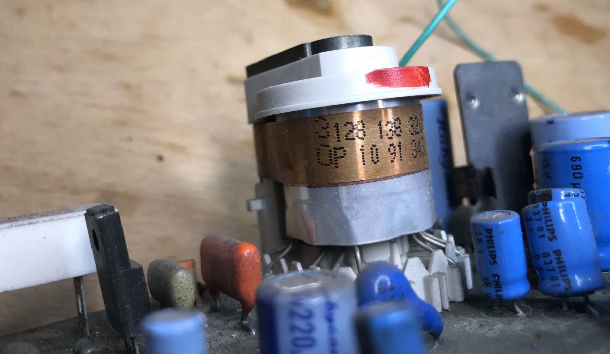
Impulse transformer:

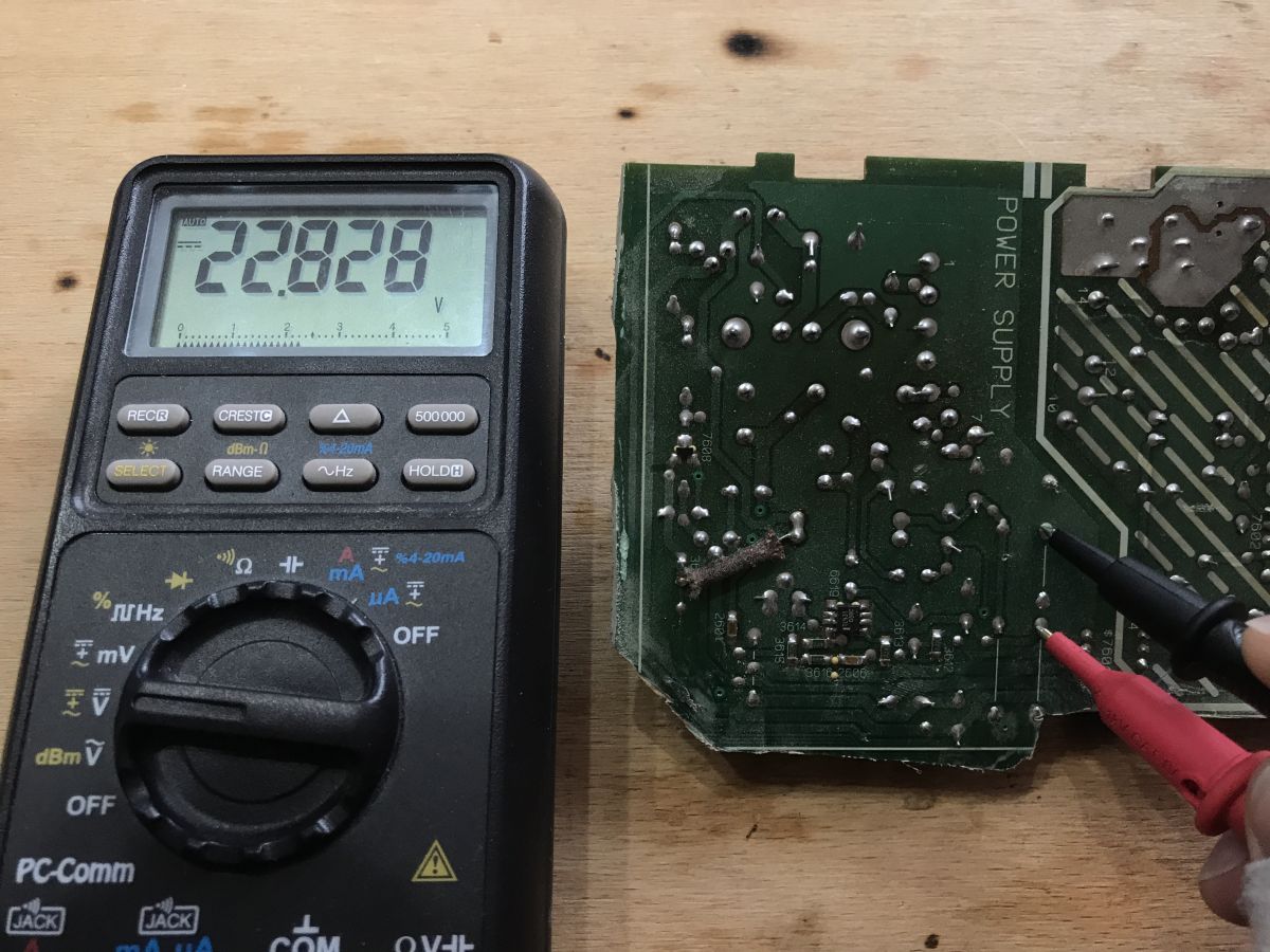
It is easy to locate the sources of individual voltages on the board (on the capacitors, behind the rectifier diodes):
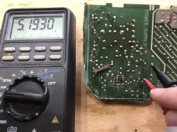
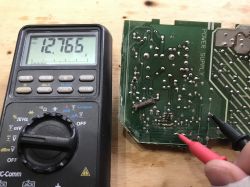
So we've got here both 5V and 12V outputs. Very standard voltages. It is indeed a useful power adapter.
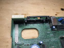
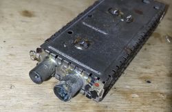
Using the ALPS RF modulator
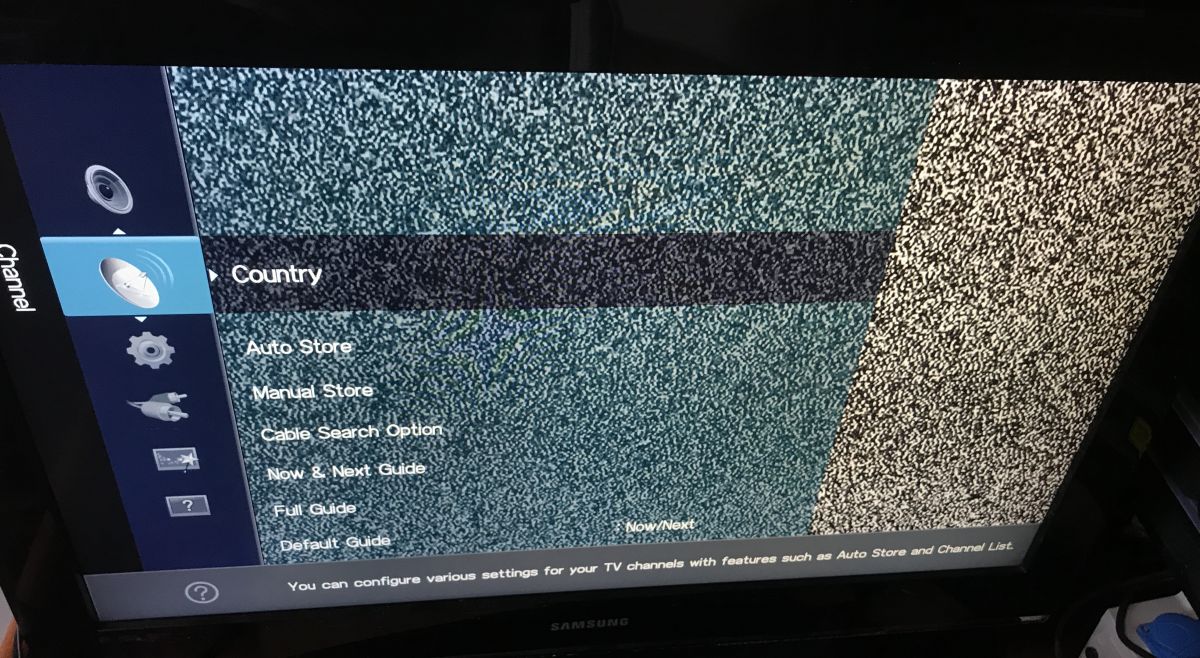
The RF modulator takes the PAL signal and modulates it so that it can be received (here) on channel 40 to 49 (depending on the trimmer setting), i.e. from 623MHz to 695MHz. Thanks to this, it was possible to connect this tuner to a TV that did not even have other connectors than the antenna input and have a 'satellite' on the normal channel right next to the regular TV channels.
It's the same with VHS players. I think I even saw an identical modulator in these.
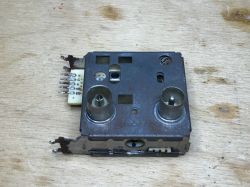
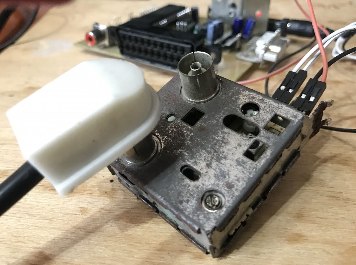
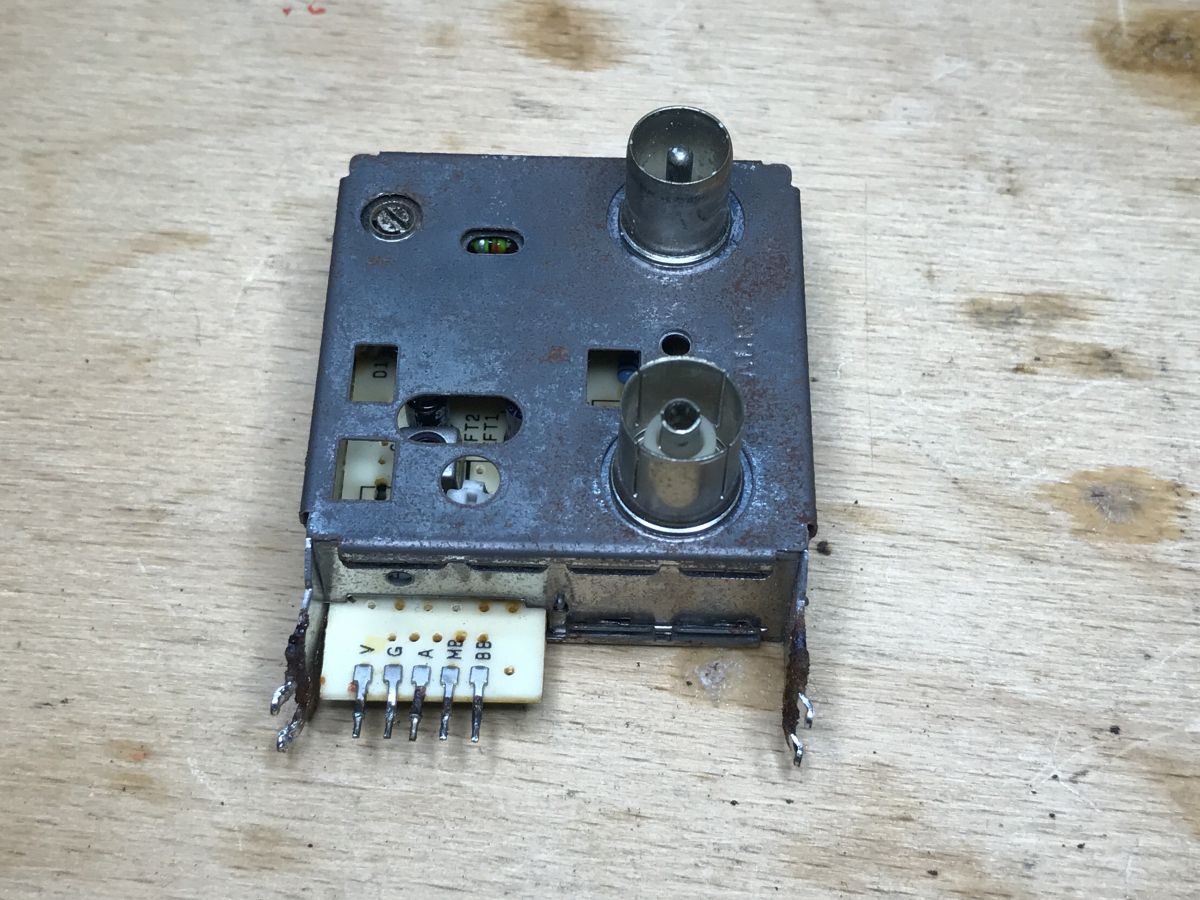
This modulator has 5 pins and looks like this:

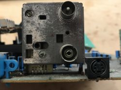
Here you can see the signal input and output, the modulator was connected in series between the TV and the antenna.
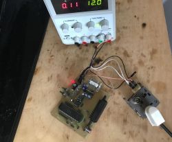
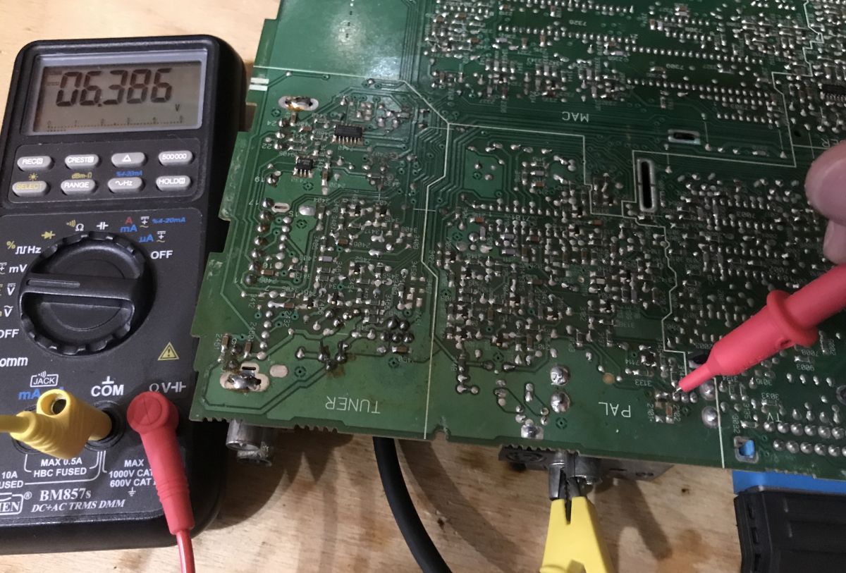
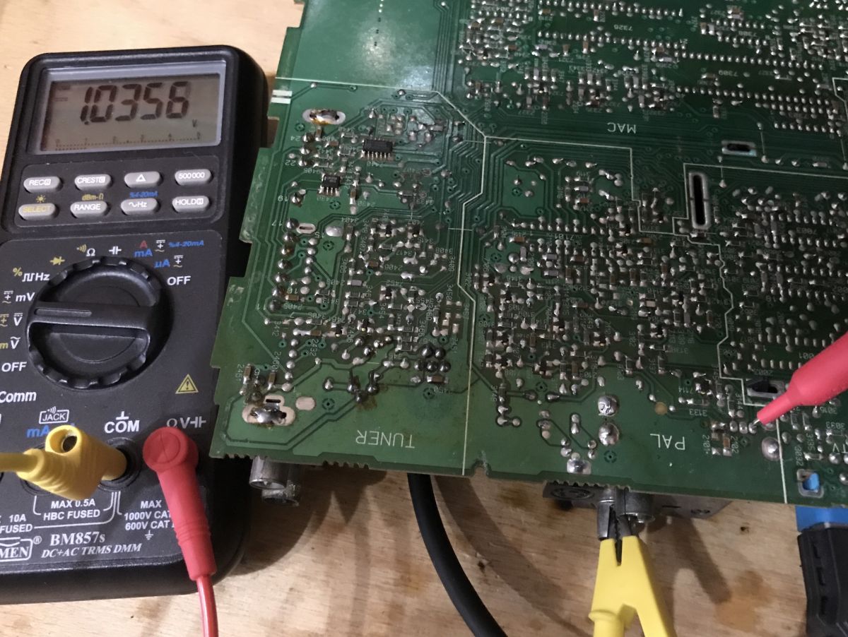
Let's measure the voltages on its pins:
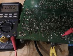


In addition, the pins have markings. Summing up we have:
- V - Video signal
- G - Ground, mass
-A-Audio
- MB (Modulator Battery) - modulator power supply that appears after turning on the device
- BB (BaseBand) - power supply from the RF amplifier that passes the signal from the antenna input to the TV, present all the time, also in standby
(Except here MB and BB are connected together, 12V is applied to them)
Thanks to @ArturAVS for explaining the abbreviations.
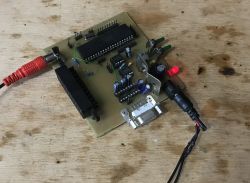
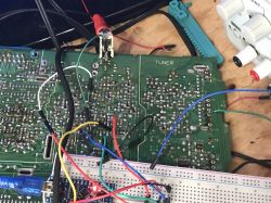
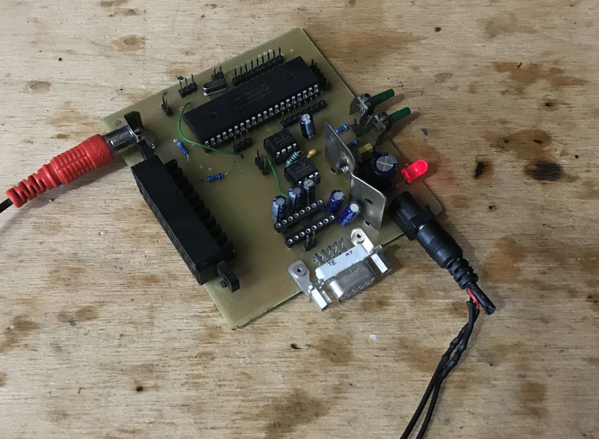
You will need some kind of PAL source for the demonstration. I'll use my old PIC PAL generator board:
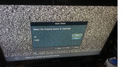
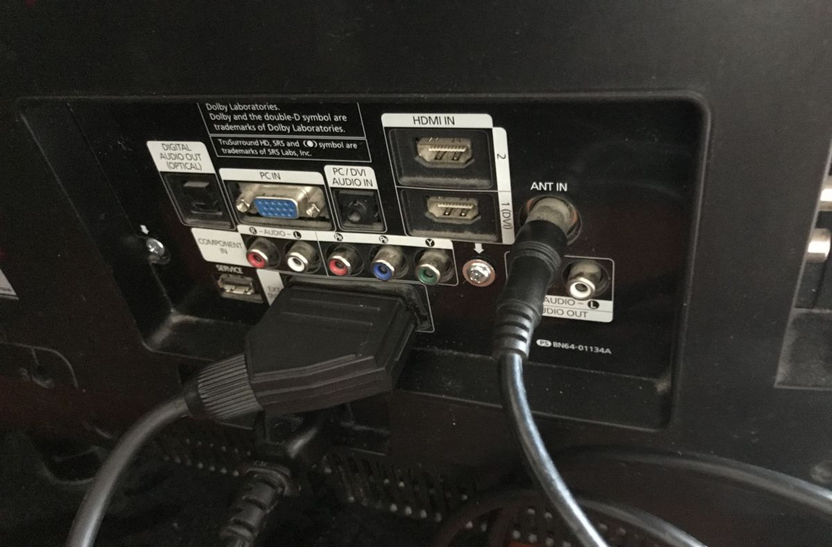
To the V pin I provide the PAL signal, the output from the modulator is connected to the TV antenna input:

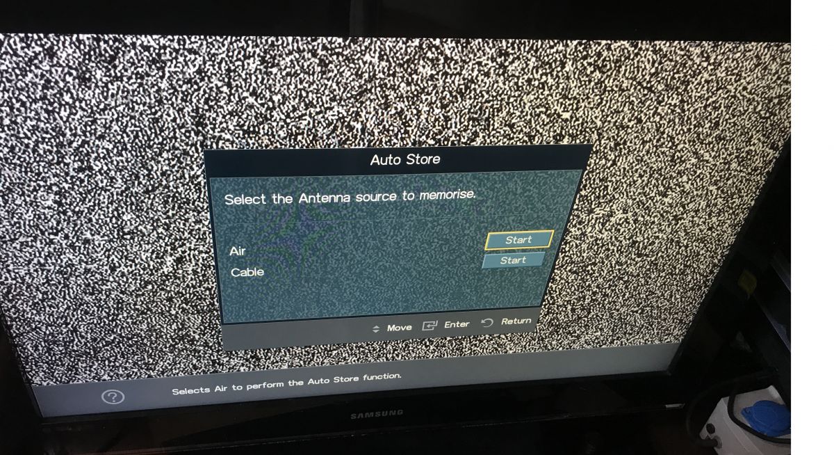
It's time to start looking for a channel:
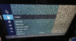
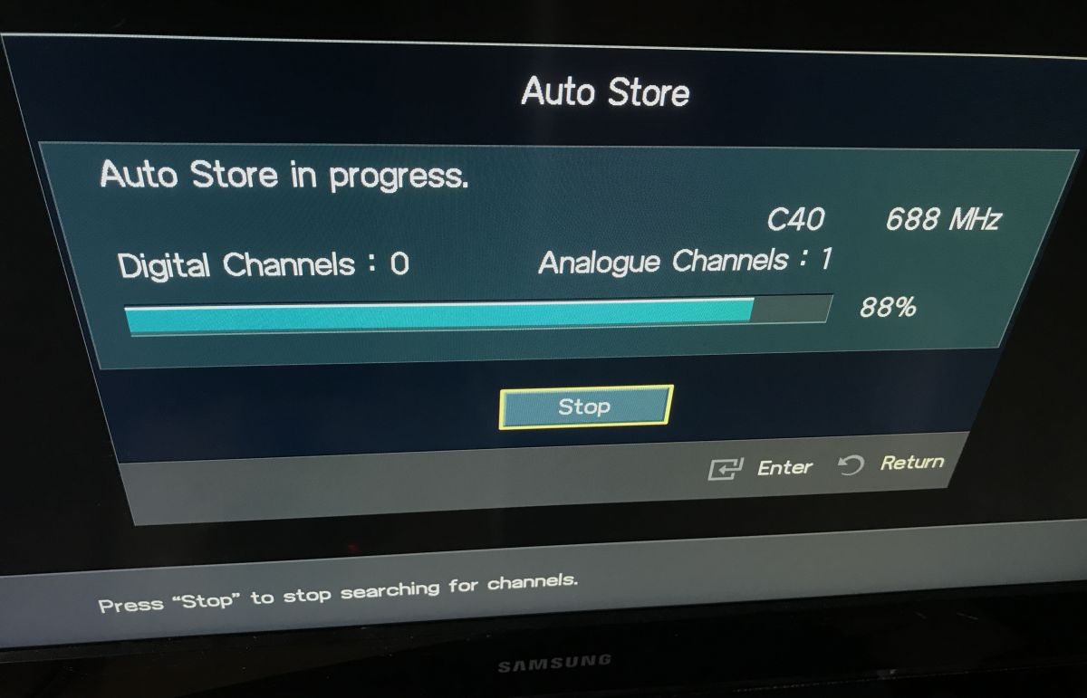
There is something - around C40, 688MHz:
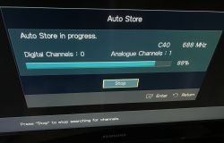
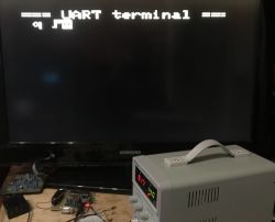
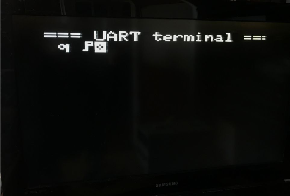
Success:
The image above is two-color, but this is a limitation of my board, not the modulator. Might as well be colored.
If you have a TV that only has an antenna connector, such PAL modulation can be very useful.
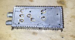
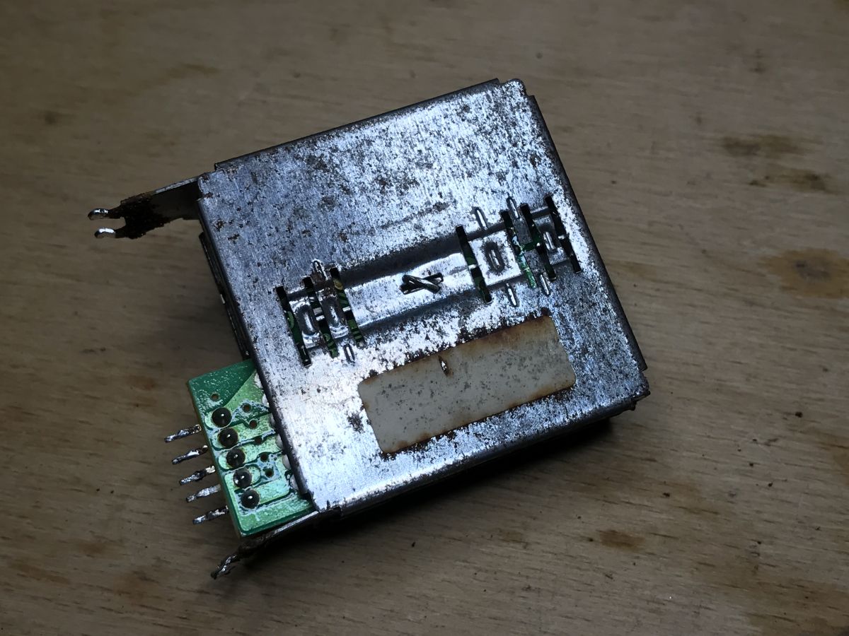
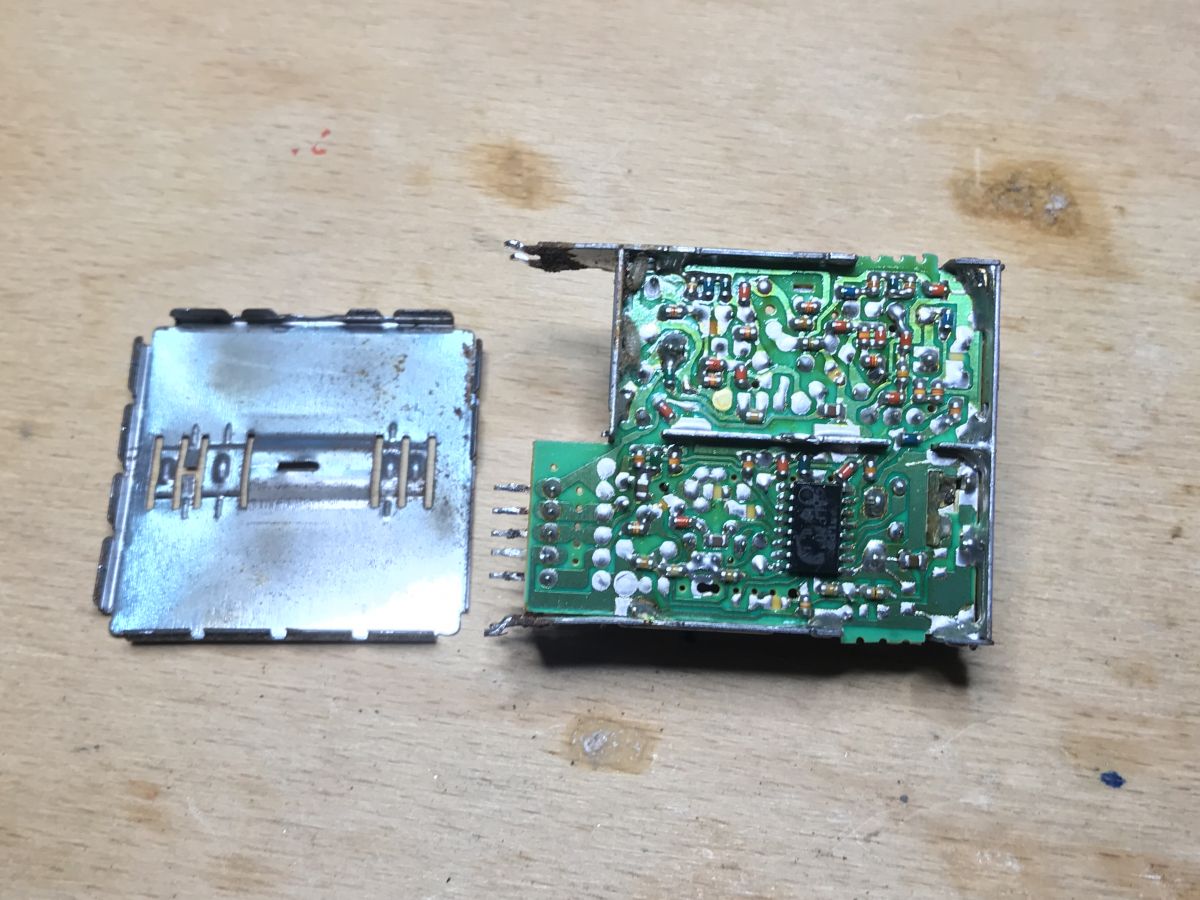
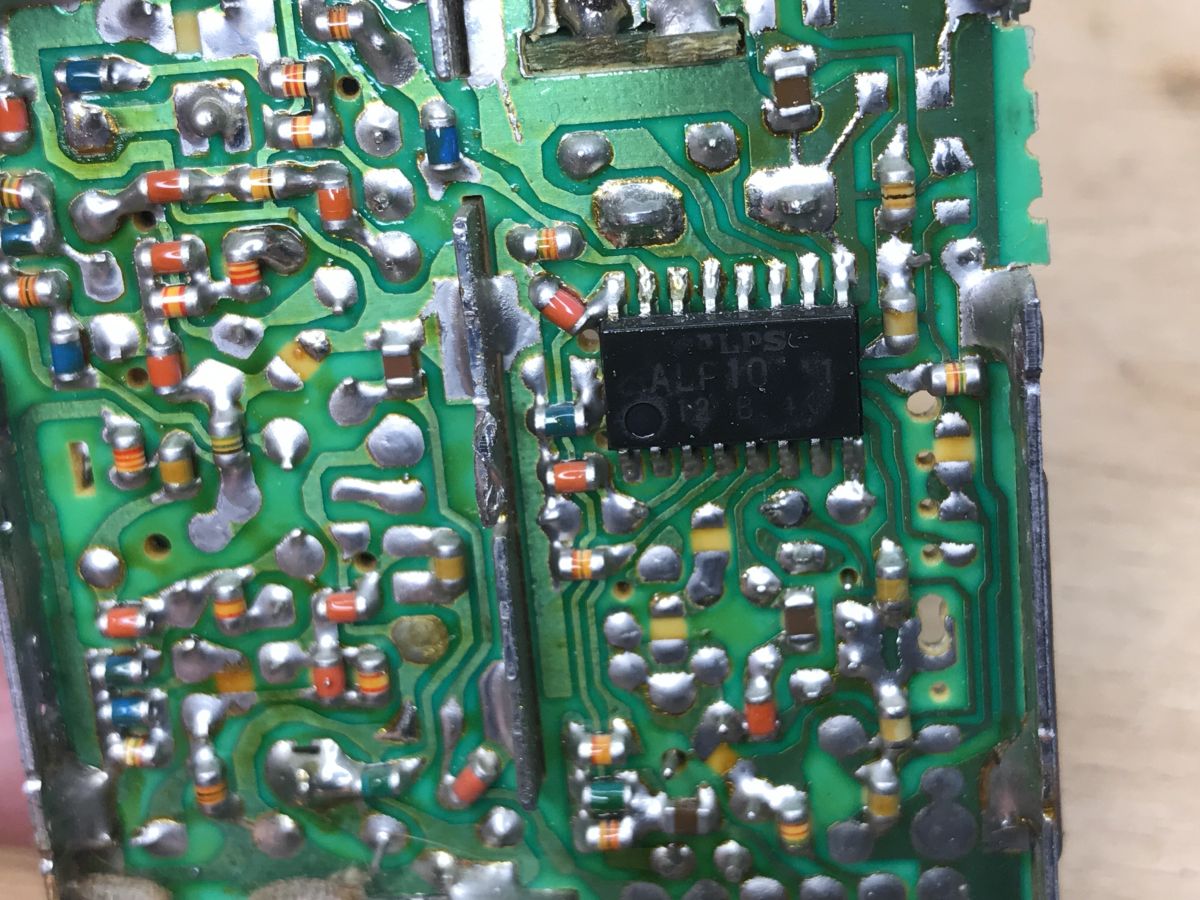
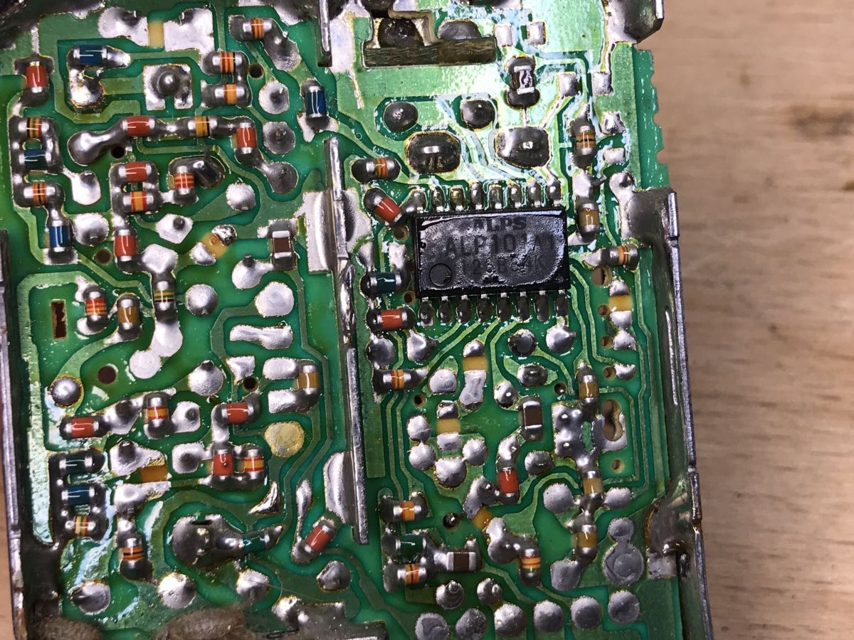
The teardown of the RF modulator (ALPS)
Let's take a look at this modulator, especially since we know it works, so it's probably more interesting.

In order to get inside, you have to turn this metal catch on the back.
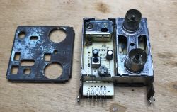
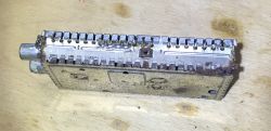
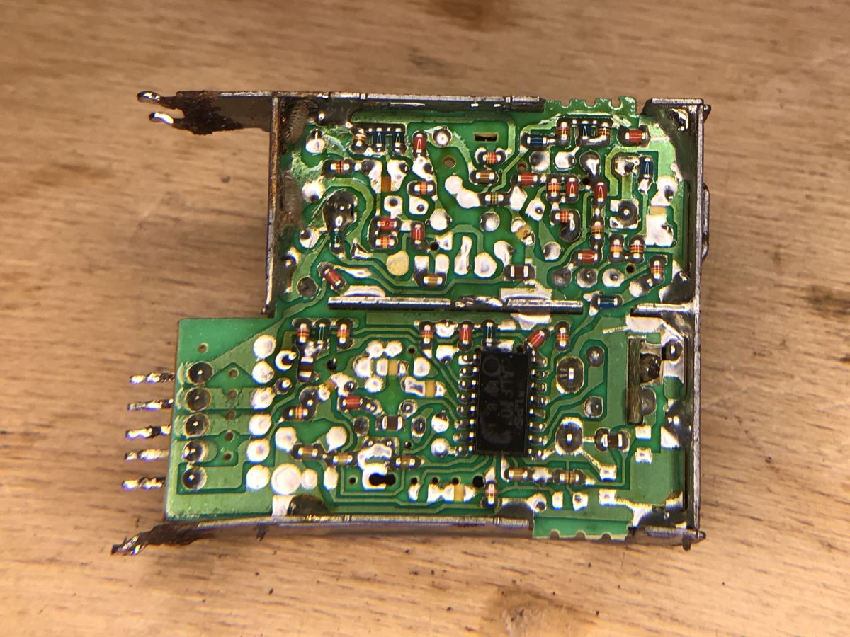
On the board you can still see old-type SMD resistors:


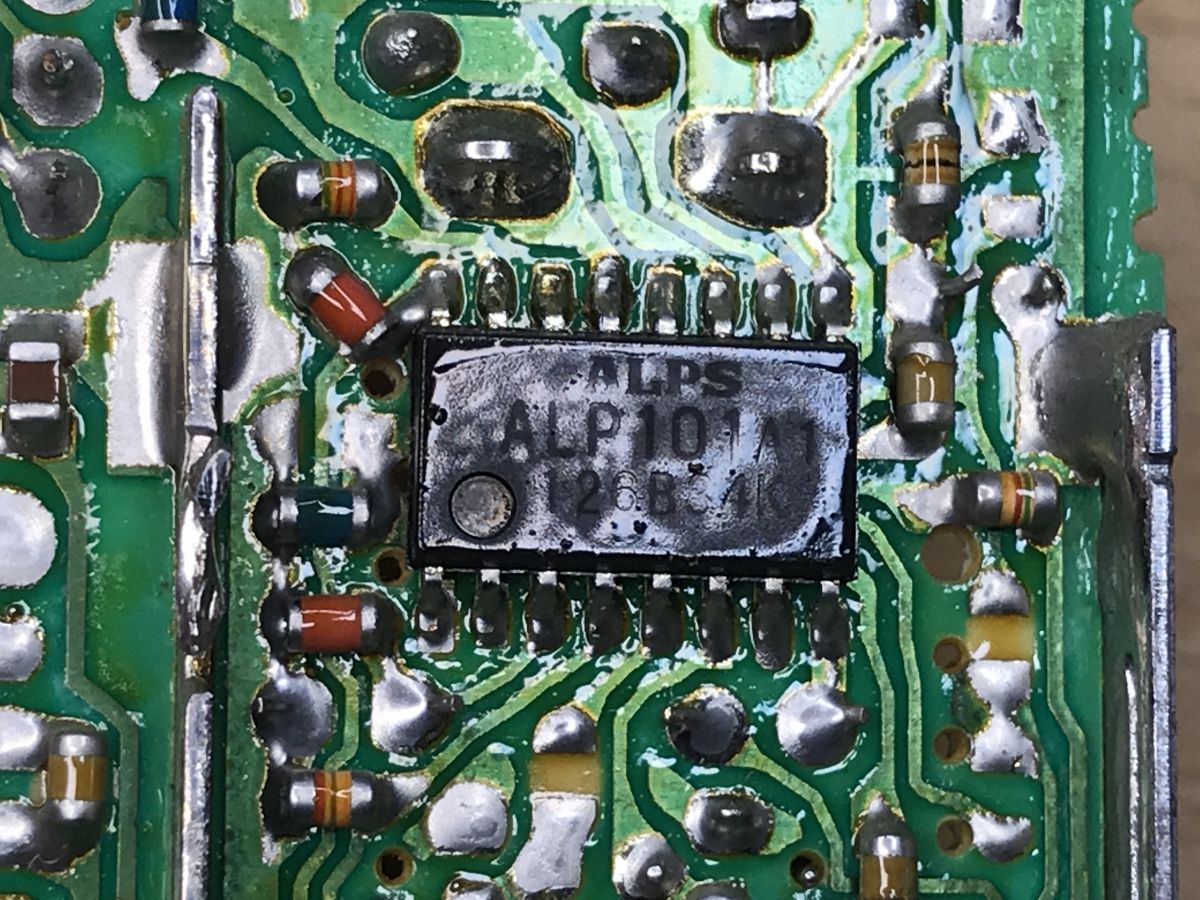
The system is based on the ALP101 manufactured by ALPS:

At the moment I have not found its catalog note.
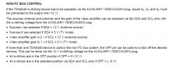
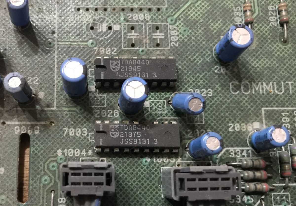
Reusing the TDA8440 (PAL switch)
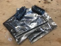
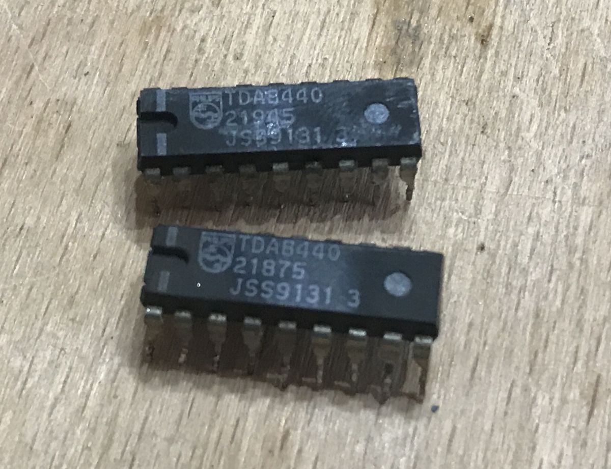
Let's try to run something else related to PAL. There are two pieces of TDA8440 on the board:
Let's desolder them:

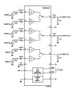
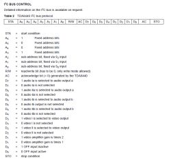
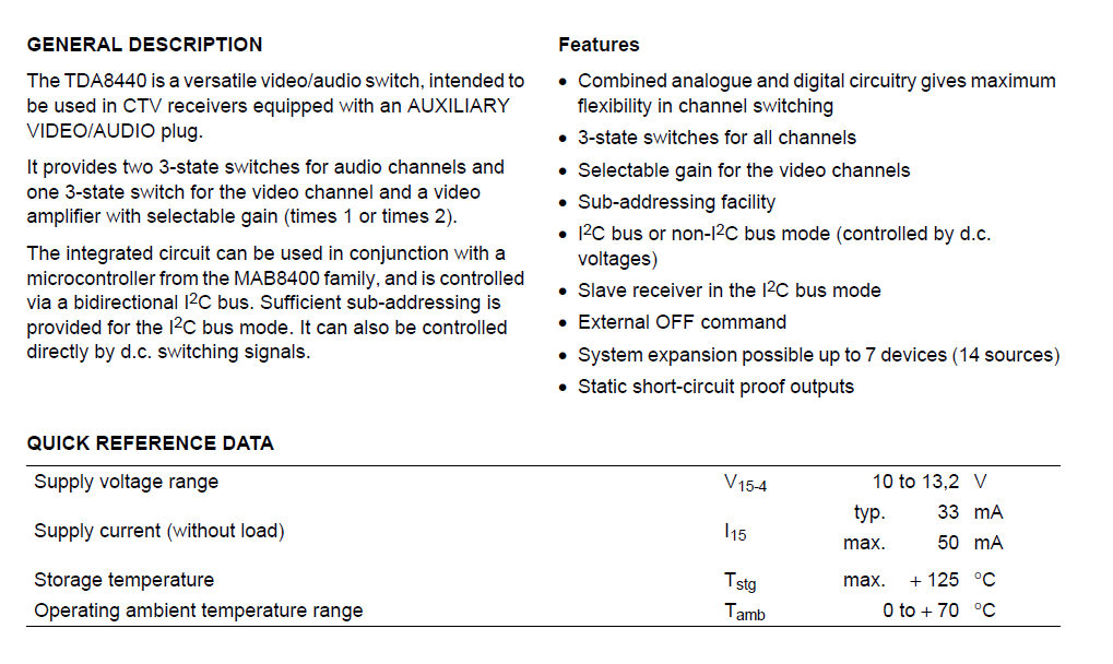
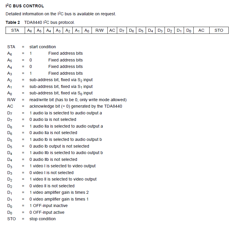
The TDA8440 is a three-state PAL signal switch (PAL video signal + separate right and left audio channels) controlled by I2C or logic levels.
internal diagram:
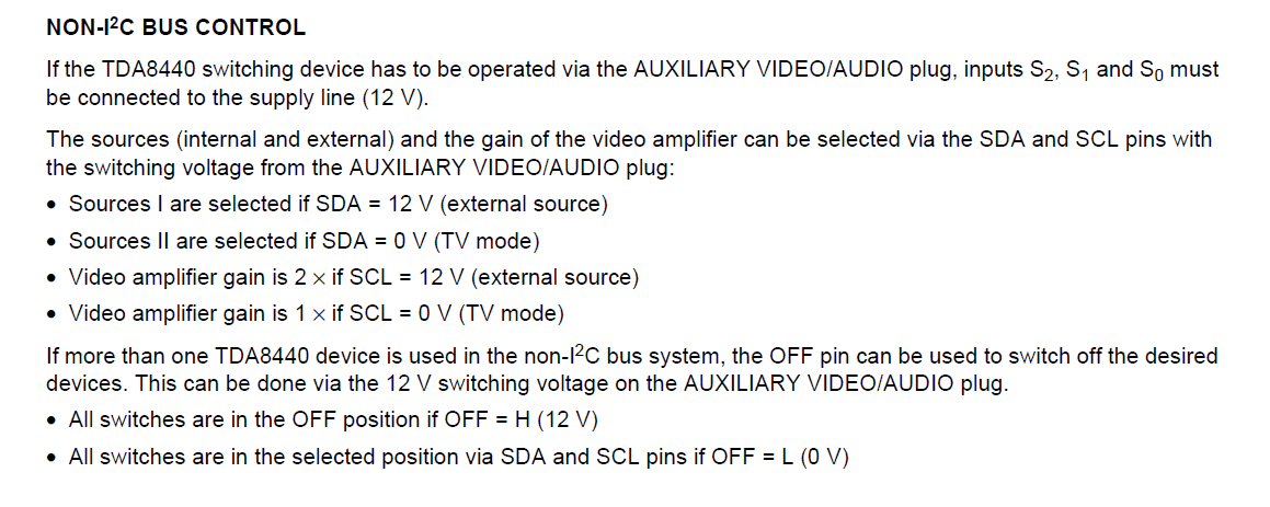
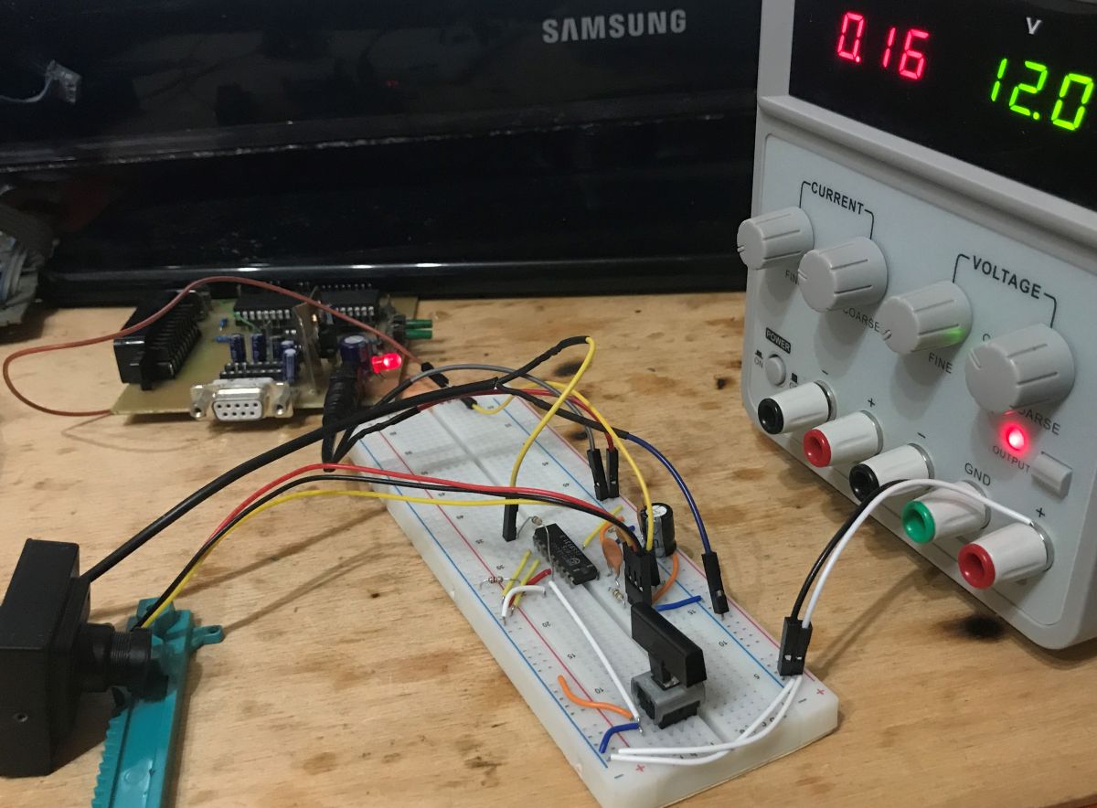
 Let's try to run it. First in logic level control mode (without I2C):
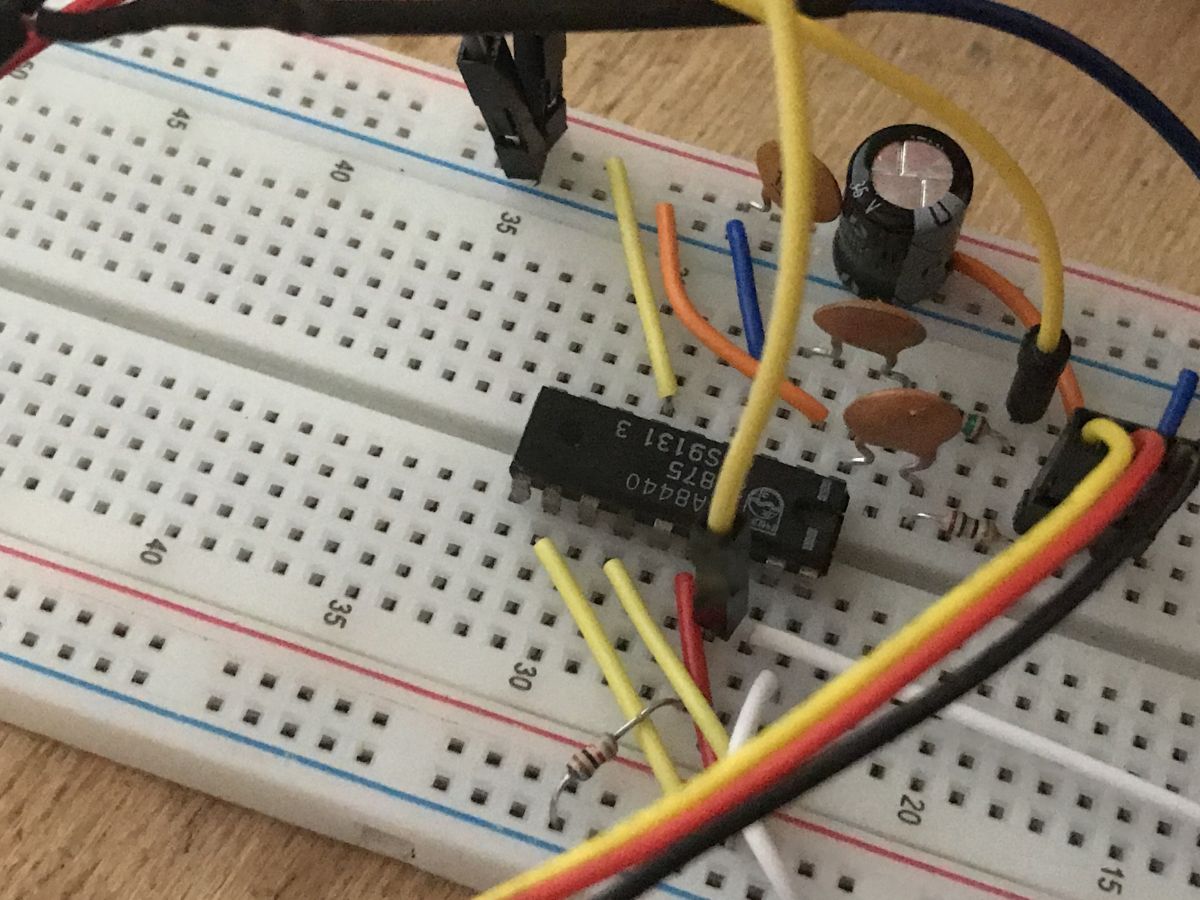
Layout on breadboard:

One input will be a PAL FPV camera, and the other will be my PIC development board generating a video image:
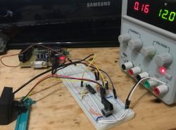
The big button in the photo changes the state on the SDA pin (in NON-I2C mode on it, 12V means the first input, and 0V the second input. I have a pull up resistor there, of course).
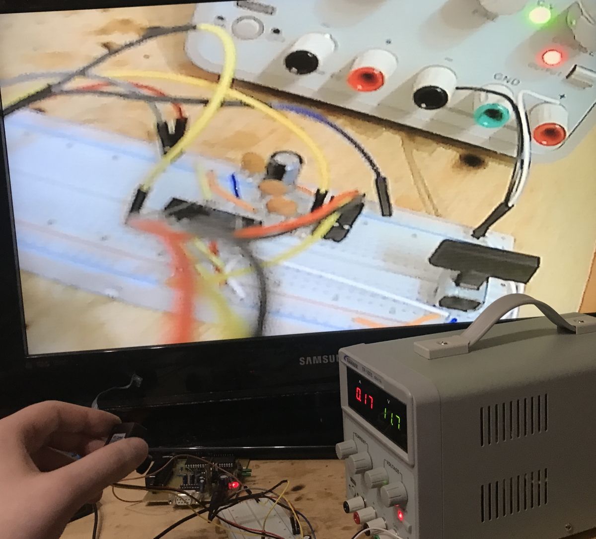
Result:
after switching:

It works and you can conveniently switch between signals.
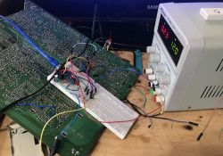
Now it's time to convert the system to I2C mode. You will need a microcontroller. For simplicity, I'll use an Arduino Nano here.
I2C here is very simple, we send only one byte of data in which everything is encoded. The bone does not even support reading, only writing.
Of course, you need pull up resistors for SDA and SCL (resistors for power supply, I think I gave 4.7k).
System:

Ready code - the program switches the PAL signal source every 2 seconds (between the webcam and my board)
0x4D is the address of the device (it can be learned from the documentation - it is partly determined by the A1, A2, etc. pins, thanks to them you can have several TDAs on one I2C bus) + W bit (write, 0), the address can also be learned by using the I2C scanner ( there is ready Arduino sketch for this). 0x04 and 0x08 are bits D3 and D2 from the previously shown packet structure, i.e. switching between two video sources.
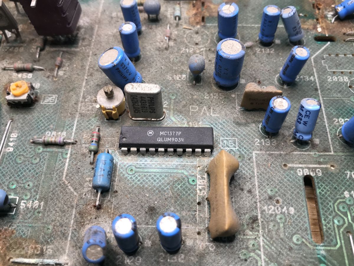
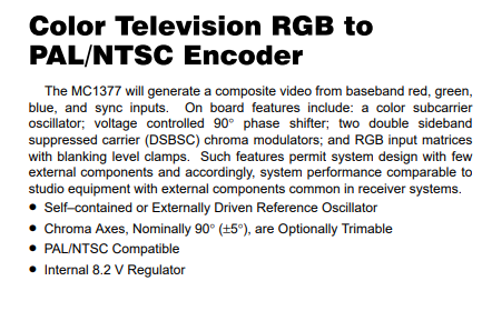
Reusing MC1377 (RGB to PAL converter)
Another interesting chip on this board is the MC1377. It is located here:
The characteristic frequency of the quartz resonator in its vicinity (4.433619MHz, 4433.619kHz) already suggests what it might be.
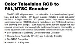
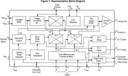
MC1377 is a converter of RGB signals to PAL/NTSC signal.
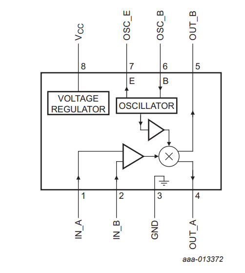
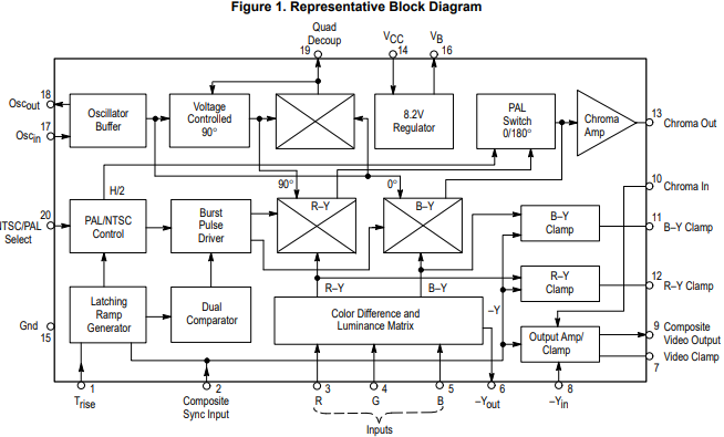
MC1377 block diagram:
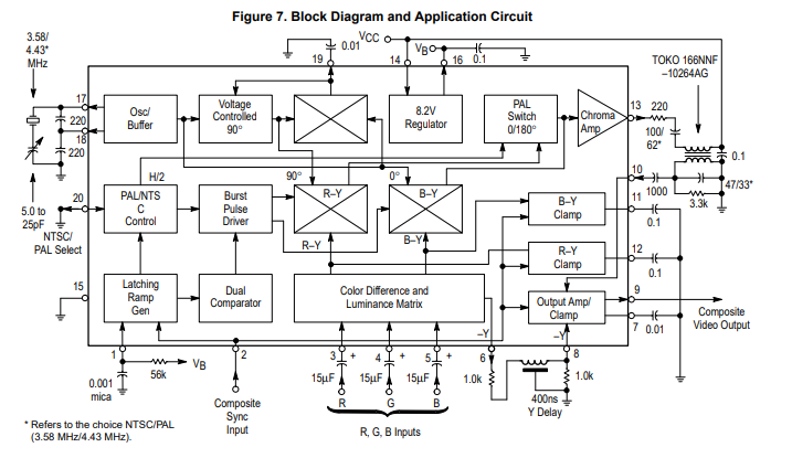
Scheme of its application (more or less what we have on the PCB):

MC1377 can do both PAL and NTSC modulation; the selection is made with the NTSC/PAL Select pin and by using the appropriate quartz resonator (NTSC 3.58MHz or PAL 4.43MHz).
In short, we have:
- analog signal R (red)
- analog signal G (green)
- analog signal B (blue)
- separate sync signal (determines pixels, which line we draw; here in one signal there will be HSync and VSync)
And at the output we get:
- PAL signal (or NTSC depending on settings)
These RGB inputs can even be from VGA as long as the frequencies match (15625Hz horizontal and 50Hz vertical, which gives us 312.5 lines as it is an interleaved signal).
In one of the Polish electronic magazines there was even a project "PAL modulator for a PC with a VGA or SVGA card" based on this chip.
We'll try to run it.
At first, you would probably just connect e.g. inputs R and G to ground, and B to the power supply and expect a blue screen, but it's not that easy:
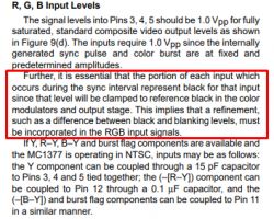
The voltages on R, G, B must be at the ground potential at the time of the sync signal and only then can we manipulate them to set the colors in relation to the values from the sync time.
So you will need 4 pins.
In addition, 5V is too much for R/G/B signals - you will need to make a resistor divider to get the necessary voltage.
And of course, relatively accurate timings are necessary - I based my program on the crib below:
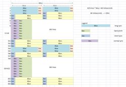 (the graphic above shows the timing of an interlaced PAL image, i.e. a technique that allows you to double the number of frames per second without increasing the bandwidth - one frame contains two fields)
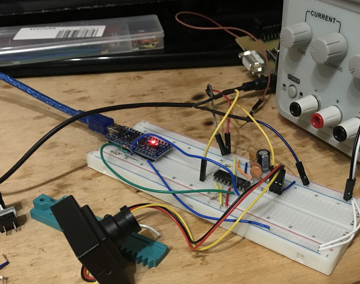
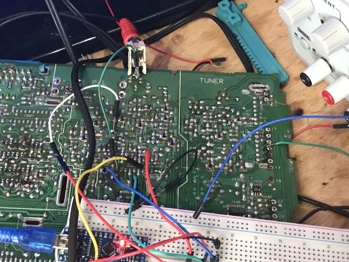
Now you need to make the connections.
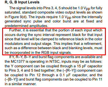
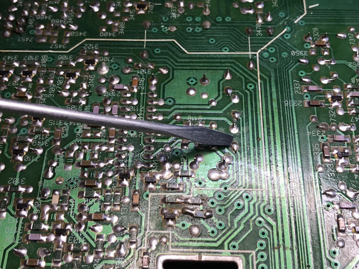
For a change, I won't desolder it this time. We'll use his layout on the original board, just cut the unwanted tracks.
It's easy to follow, for example here are its RGB inputs with capacitors:
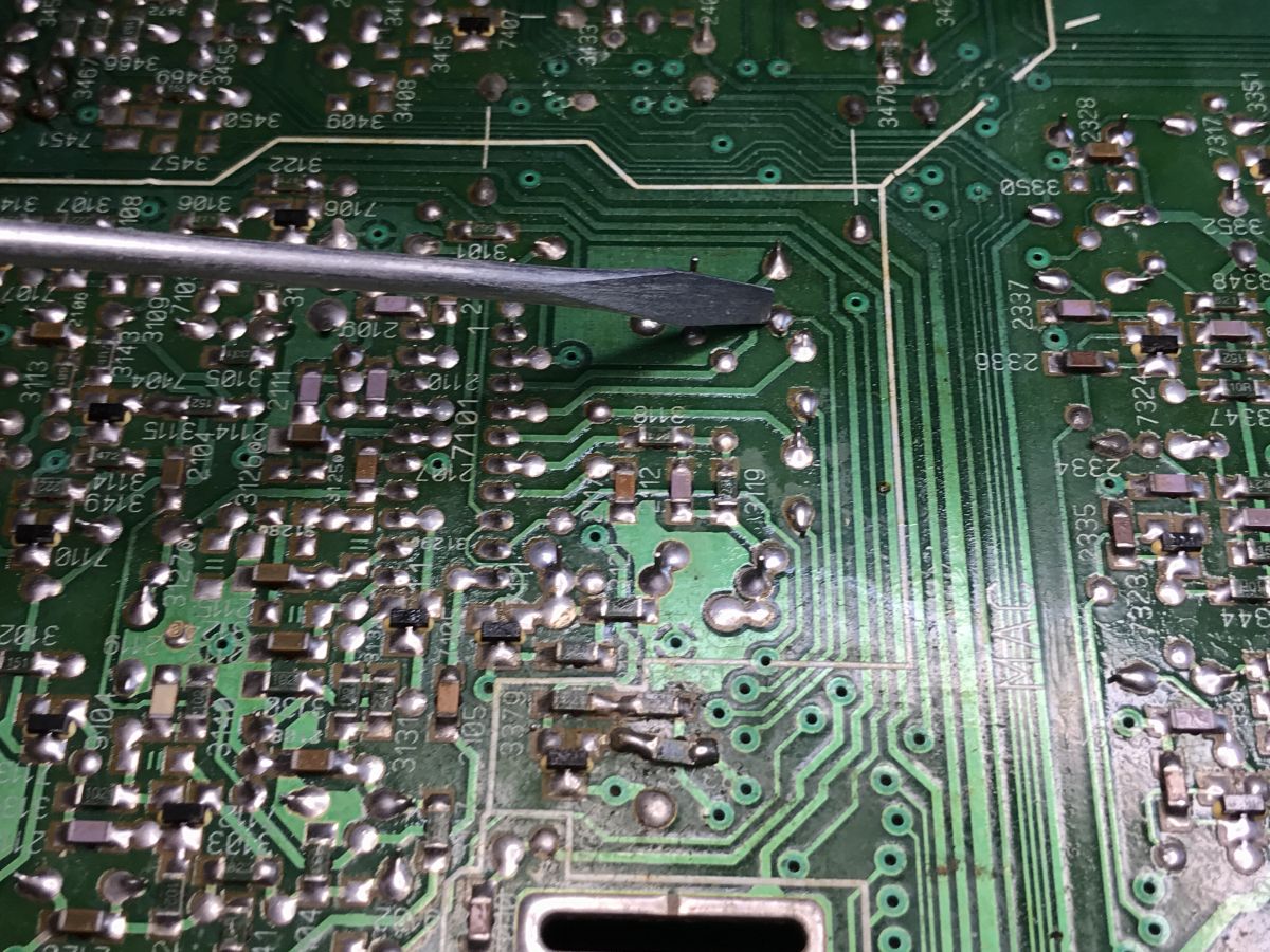
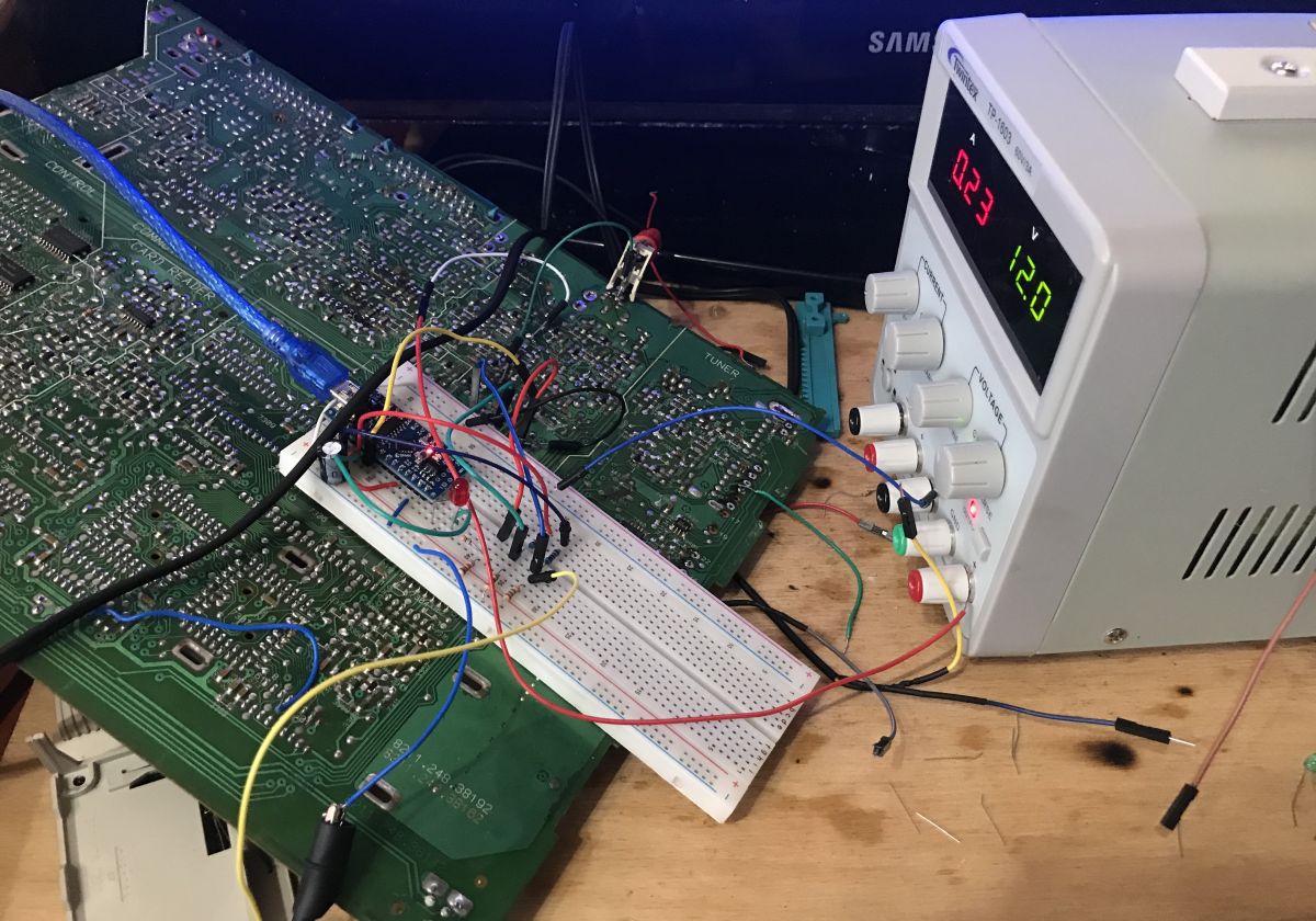
A few moments and we have a ready layout. Arduino Nano and resistors (resistor dividers) to have these 0.7V on pins from RGB. I used port C (PORTC), necessarily everything on one port to make the state settings last faster:
Now let's try to implement it. It would be best to do it on interrupts. If we want without, it would be useful to count the time of one NOP on the platform used, because the delay function may not be as accurate, but I managed to do it with delay. This is the simplest option, the least efficient and blocking the processor completely, but it allows you to visualize the operation well.
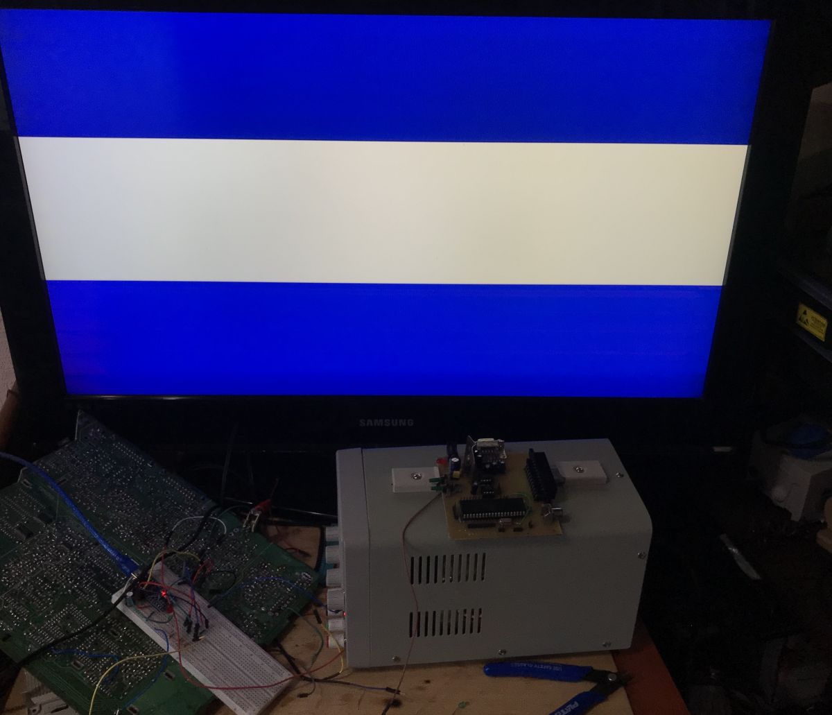
The first example, the blue belt. It's easiest to do it horizontally.
The line numbers in the comments correspond to the lines in the Excel graphic!
In this way, we create a bar.

In the above code, I used a preprocessor macro to generate one line, and the macro takes arguments to determine the length of the sync signal.
The values of MS_2 are also created by #define because I want everything to be optimized during compilation. #define is also used because delays are not suitable here, and the instructions themselves take some time, so the actual waiting time in microseconds (uS) for, for example, MS_30, is not exactly 30 but less.
That was simple because the stripes were made "along the lines". Let's try to make a vertical stripe. That means across the lines.
Well, it seems that's why delays in the code should be in line with the PAL specification, and in my case, they are not. It could be done better, but I didn't want to scare beginners with assembly language inserts and "nops":

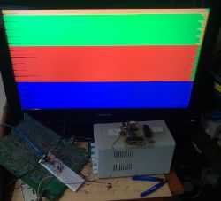
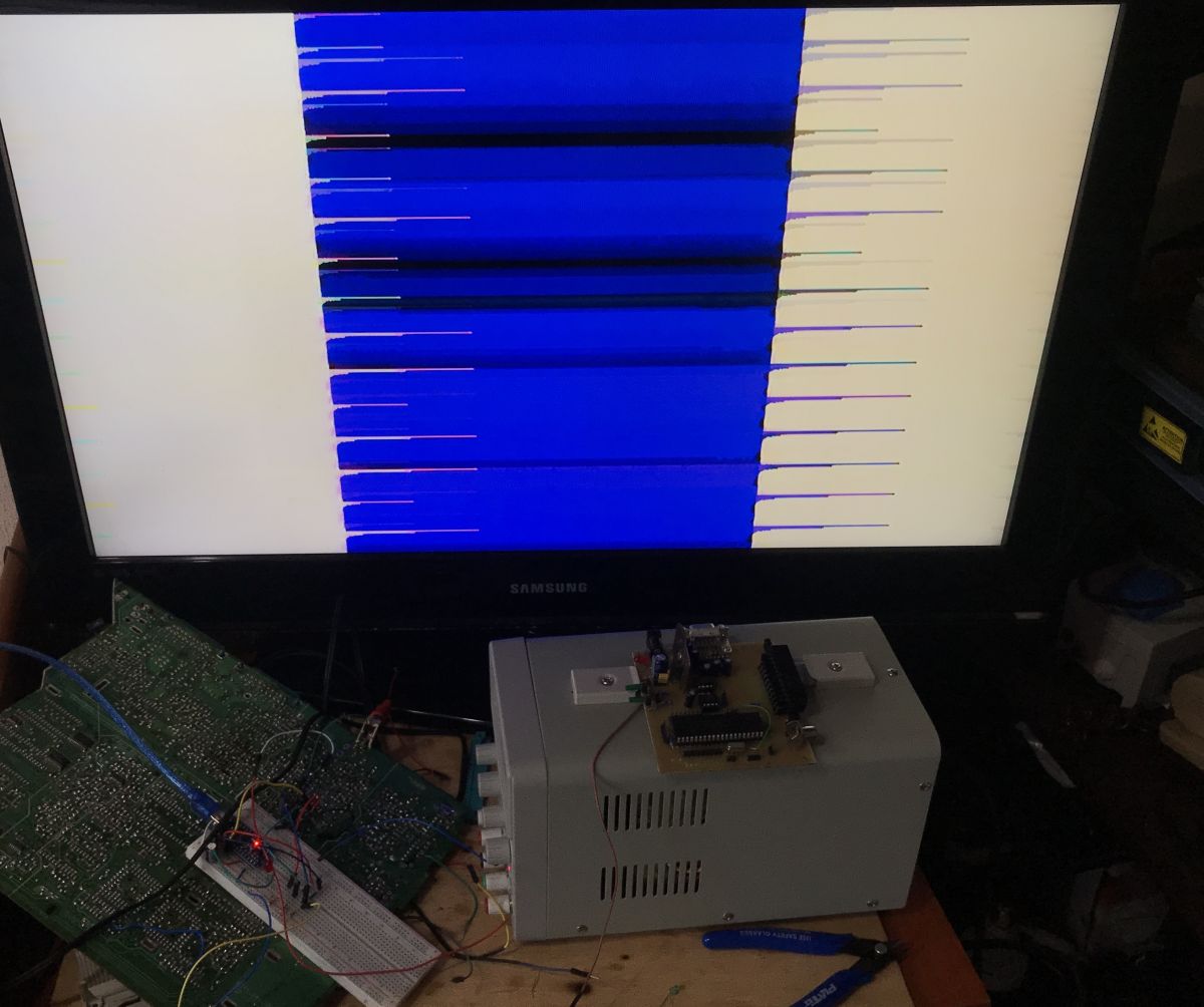
Now, it's time to create the "three kings of colors," that is RGB stripes. Maybe as a bonus, also with some animation, so that these colors of stripes swap places over time. Here's the code:
Result:

In summary, the MC1377 definitely works. The code itself could be significantly improved, both in terms of cosmetics (calculating better delays and using NOPs to comply with standards) and in terms of functionality (e.g., using interrupts, as it should be done in the final implementation).
Outside of this topic, I can recommend looking into the TVout library for Arduino:
https://www.arduino.cc/reference/en/libraries/tvout/
Repository:
https://github.com/Avamander/arduino-tvout/
However, please note that this library generates images in only two colors: black or white. Unlike what was presented here, it directly generates the PAL signal without the need for external circuits.
Sat tuner
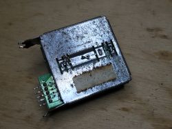
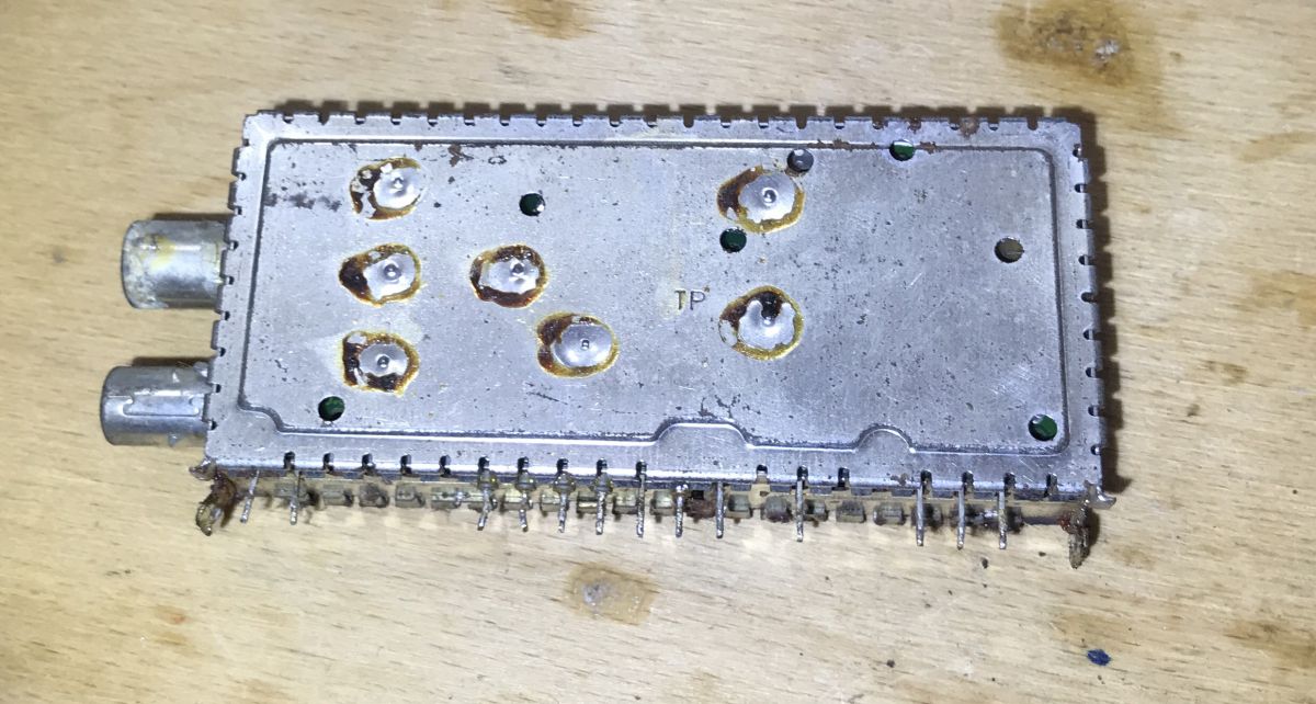
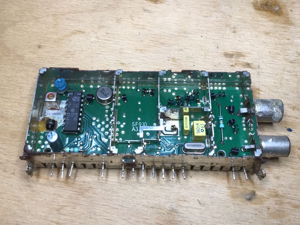
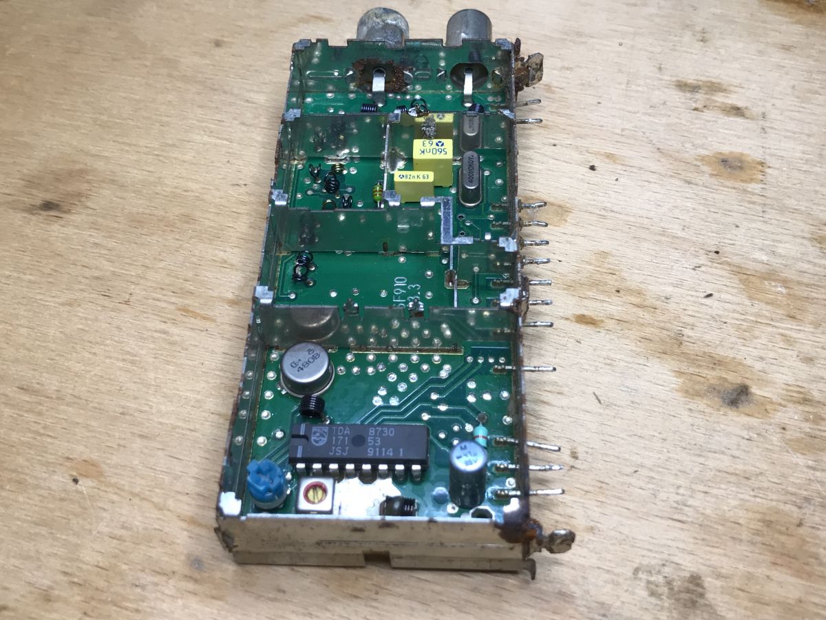
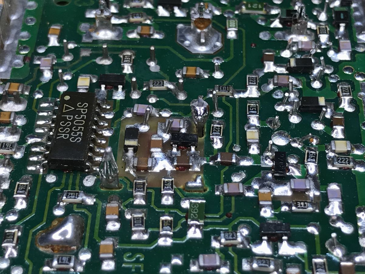
Now, let's take a look at the demodulator for a satellite signal, also known as the 'sat tuner':
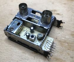
The visible droplets are solder holding the cover. Sometimes they are closed this way, and other times just with bent metal sheets. After removing the housing:
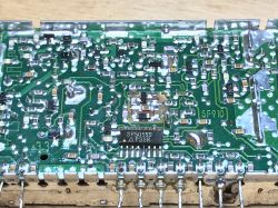

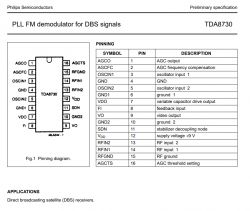
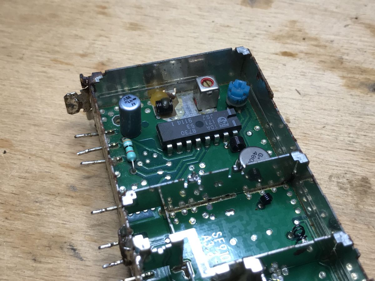
Inside, Surface Mount Technology (SMT) is mixed with Through-Hole Technology (THT). There are two integrated circuits - TDA8730 and SP5055S.
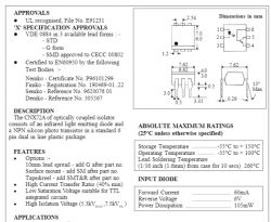
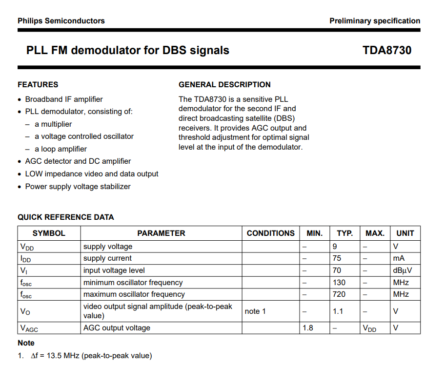
TDA8730, here in a DIP package (through-hole assembly), is an FM demodulator with PLL for Direct Broadcasting Satellite (DBS) signals, including a built-in Automatic Gain Control (AGC). From the datasheet, you can find the frequencies it operates on:
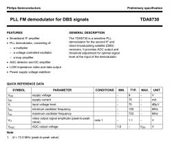
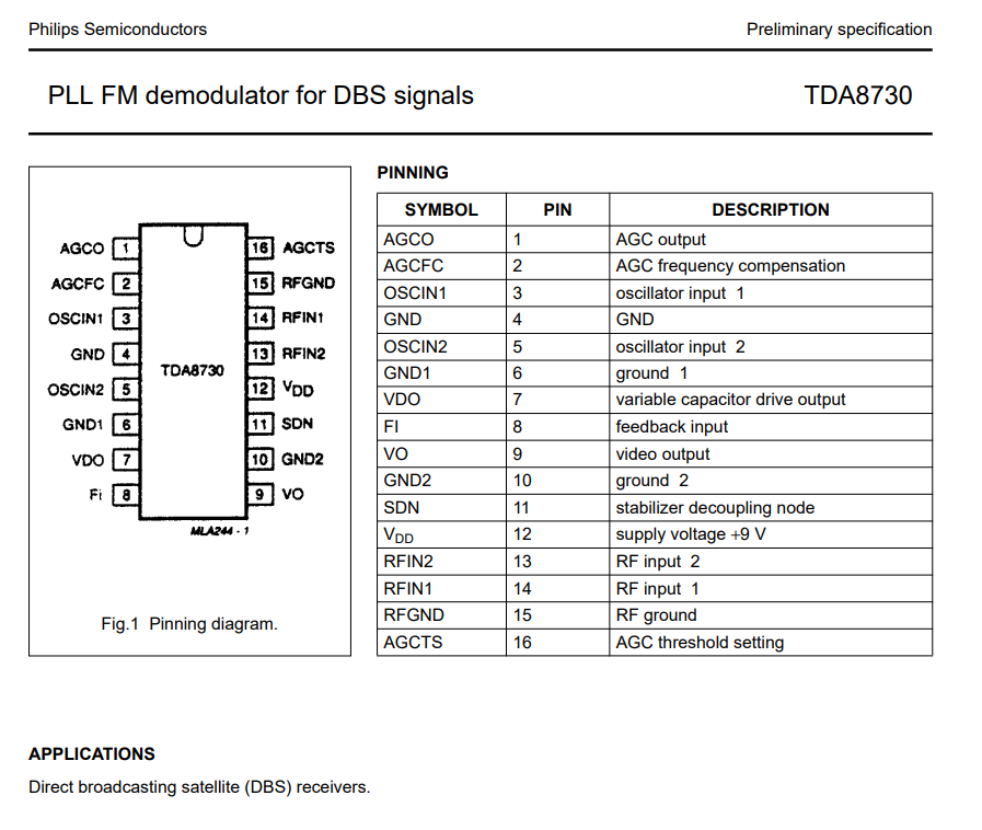
Its pinout:
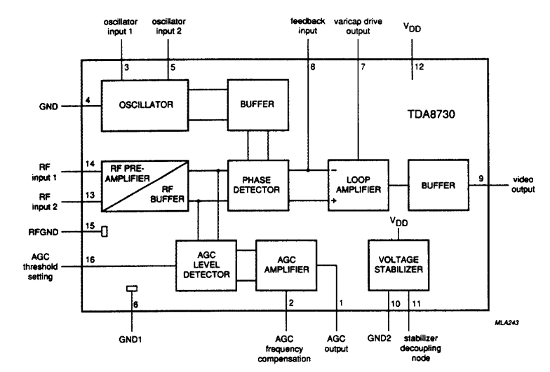
Internal schematic:

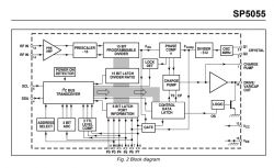
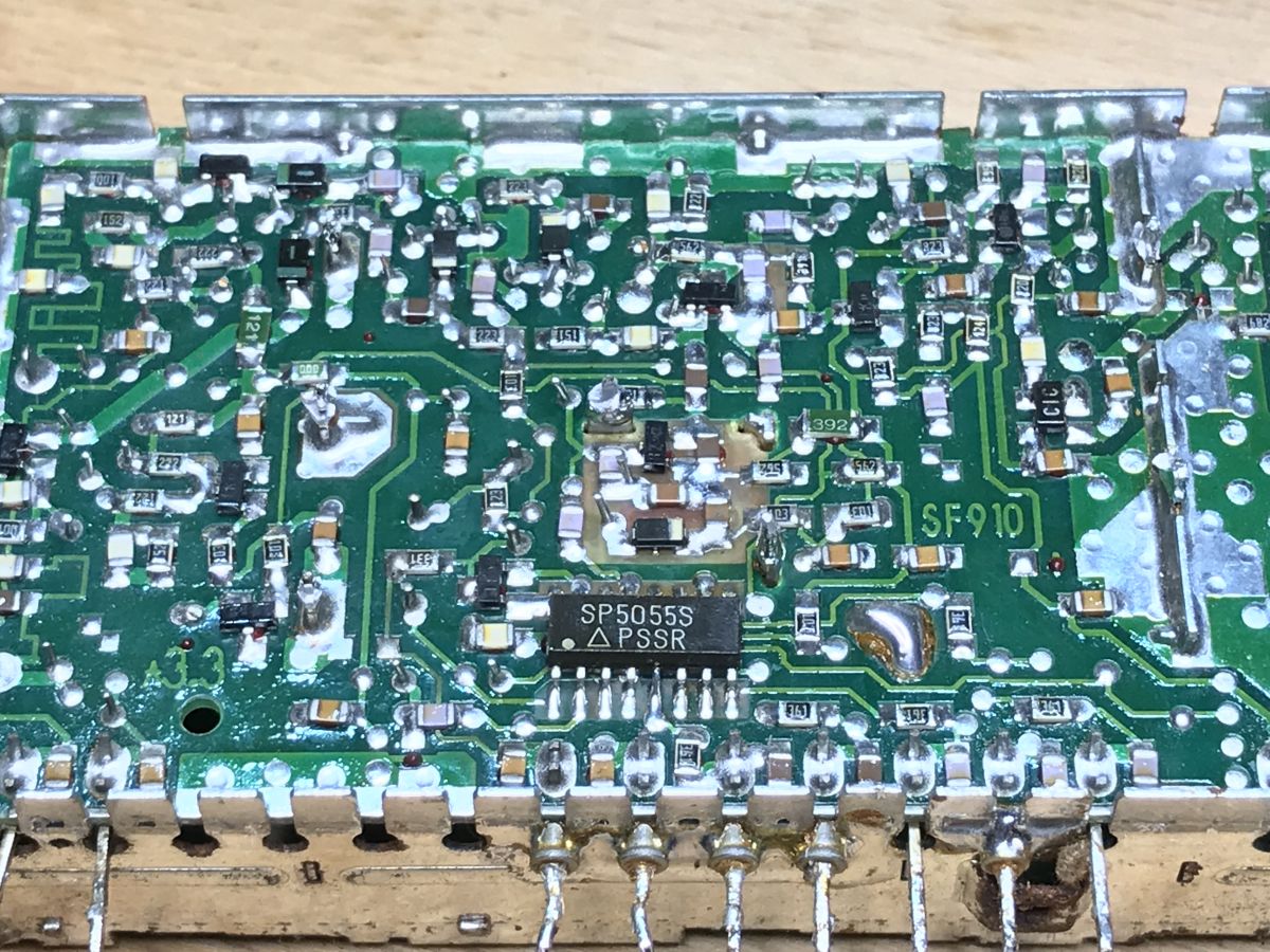
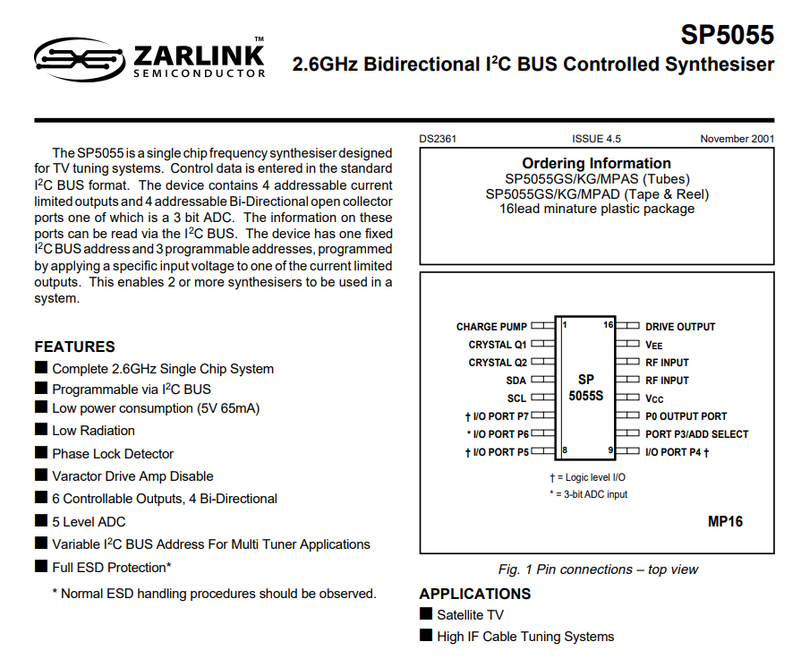
The second integrated circuit inside is SP5055S, controlled via I2C as a synthesizer:
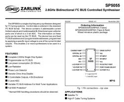
Internal construction:
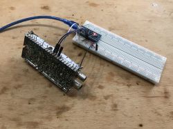
 Sat tuner - first I2C attempt
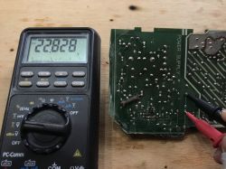
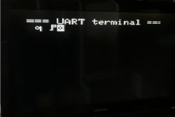
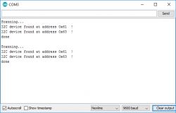
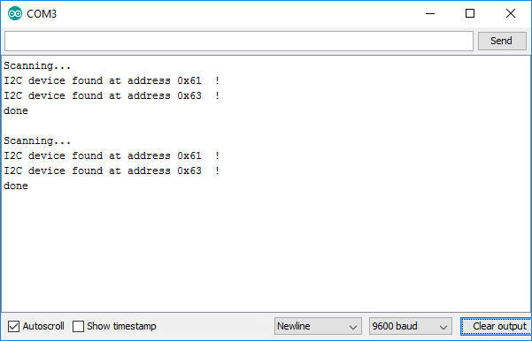
It's effortless to connect such a satellite head to a microcontroller; you just need two pull-up resistors for I2C, and that's basically it. More work lies on the code side. So, here I'll only check if Arduino detects it on this I2C (using an I2C scanner), and that's all:
Rezultat:
You can take this further and, depending on what you have, create various types of receivers, frequency scanners, spectrum analyzers, etc. However, it's a fact that the ease of access and the price of SDR (Software-Defined Radio) devices have reduced the need for this kind of experimentation.
Summary
I presented here the interior of an old, even rusty, Kathrein satellite tuner and demonstrated that even in such a condition, the components inside can still be useful for something. This tuner differs slightly from its newer counterparts because it contains a variety of elements, and it's easy to isolate individual blocks responsible for signal processing along the path antenna->C/D/D2-MAC->RGB->PAL/NTSC. In newer tuners, everything is more integrated into specialized components, and there aren't as many useful parts as there are here.
Each "seed" shown here could be further developed into a full-fledged, interesting, and unconventional project. This could be particularly attractive to people who enjoy understanding how the equipment around them works and/or are interested in retro topics, as PAL, of course, is not used as much as it once was, but I don't see that as a problem.
PS: Of course, many more parts could be used from the inside, such as the 7-segment display with two digits or the NE612 (aka SA612) mixer circuit, which would be perfect for a first DIY shortwave receiver, for example, on the 80m band, and you can already listen to SSB... And I won't even mention the 74HC series and operational amplifiers...
PS2: Now I see that I could have also activated the TSA6057; there are even codes for it available online, but maybe another time.
For those interested, I am adding a part of the catalog notes to the attachments.


Comments
I see minor but significant inaccuracies; It is not a PAL modulator, but an RF modulator, the PAL modulator is MC1377 (depending on the configuration, also NTSC) used to change the RGB+Sync signals... [Read more]
Thanks for your comments, I have corrected the issue. Indeed, I guess I have a bad habit of calling the RF modulator PAL, because its input is PAL. Czech error. EDIT: As for the MC1377, I recommend... [Read more]
The device was not in such a bad condition, I disassembled the ones where there were no paths, and after applying the soldering iron to the PCB, a hole burned out :) Great article, it's nice that... [Read more]
What is this grotesque? There is no such thing as "PAL modulation". The video signal to the PAL standard is not modulated, but encoded. [Read more]