We have probably heard the term "magic eye" referring to the tube technique many times, but few people, especially the younger ones, know what it is about. So I will explain what we are dealing with. The so-called
Magic eye is a vacuum electron tube whose task is to signal the voltage level. In the tube era, it is mainly used as an indicator of tuning or actuation in radio receivers and measuring equipment. The basis of its operation is a screen covered with the so-called A phosphor, i.e. a substance that glows under the influence of the electrons incident on it, emitted from the cathode, as well as in cathode ray tubes (CRT) or oscilloscope tubes. On the path of electrons from the cathode to the screen, one or more electrodes were placed, which appropriately shaped the beam, giving the desired visual effect. Most of these tubes also contained a triode internally connected to the control electrode (s) in one bulb, tubes with triode electrodes were also produced to be used as an amplifier, eg AM2. There were also tubes without an integrated triode, such as the American 6AF6. The very use of the internal triode as an amplifier generated quite a lot of difficulties, which was solved by the use of a pentode. It improved the work of the indicator and the amplifier, one of such tubes is EFM1. One of the first indicators
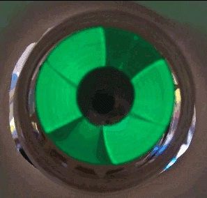
Magic eye was introduced in mid-1935 by RCA's 6E5 tube. The lamp in the upper part of the bulb had a conical screen placed inside. This screen, viewed from the top of the lamp, had the shape of a ring on which darker or lighter green segments were visible, with a size and shape depending on the voltage applied to the lamp's driving electrode. By changing this voltage, you can control the opening of the dark sector. Lamps were produced in various versions, differing not only in terms of electrical parameters, but also the shape of the screen. Although the name
Magic eye adhered to this type of lamp due to the cat's eye-like appearance, lamps were also produced with a different screen shape in the form of a strip or an exclamation mark. Below, a photo of the EM11 lamp taken from Wikipedia.
Although today most of these lamps have passed away with their epoch, they are often used in amateur constructions because of their unique charm. Only lamps with a typical shape
Magic eye Not much can be found today, however, those with a screen in the form of a strip are quite popular, such as the EM84 or EM87 or EM800. If you are interested in the subject of these lamps, please have a look here;
http://www.magiceyetubes.com/ You can find there a lot of valuable information that will surely be useful.
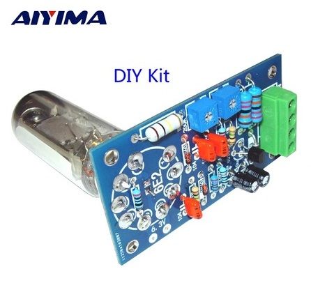
Coming back to the title indicator, it is an interesting alternative to the tilt indicators, which often act as a control or power indicator in amplifiers.. The module in the form of a kit for self-assembly (putty) can be purchased for several dozen zlotys on a well-known portal. To run, we need a 6.3VDC power supply (lamp incandescent) and 250-300VDC.
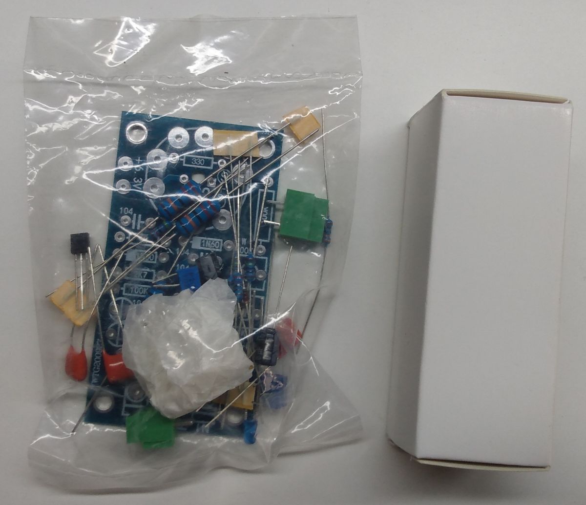
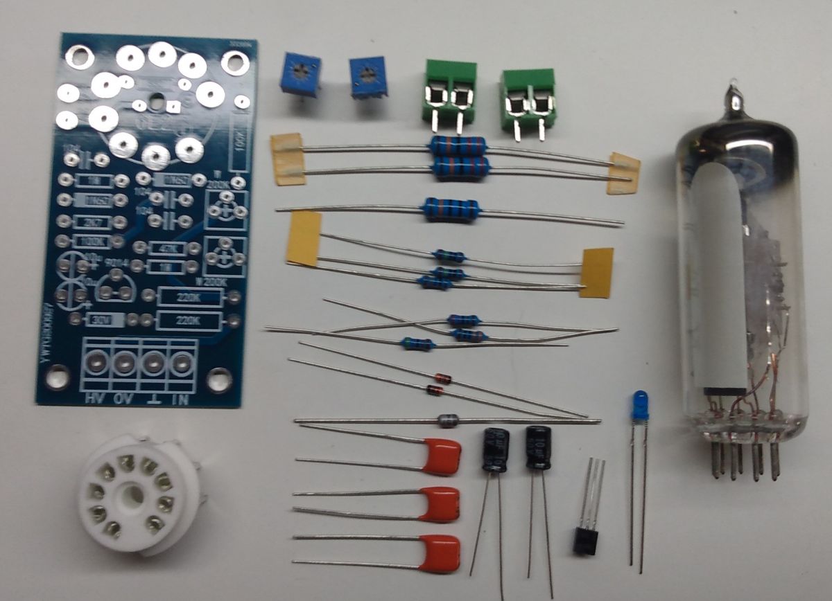
Here, however, let's remember that there are no jokes with the flow! The kit does not need high current efficiency (several mA), but you can never be too careful. The set is delivered in a small string bag;
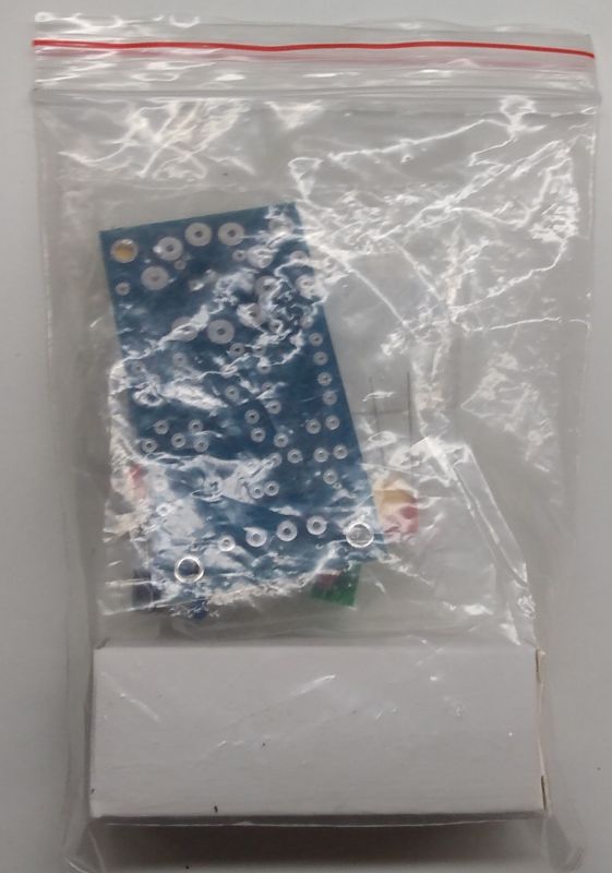
Inside, in another bag, there is a PCB and the necessary elements, and in a separate small box is ours
Magic eye ;
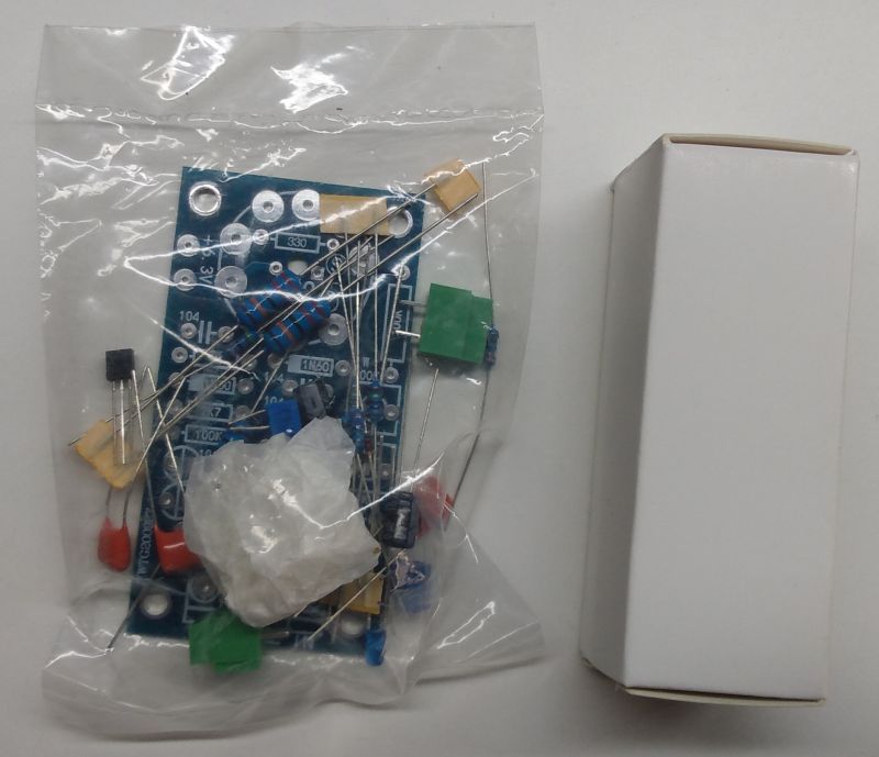

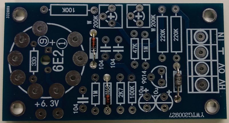
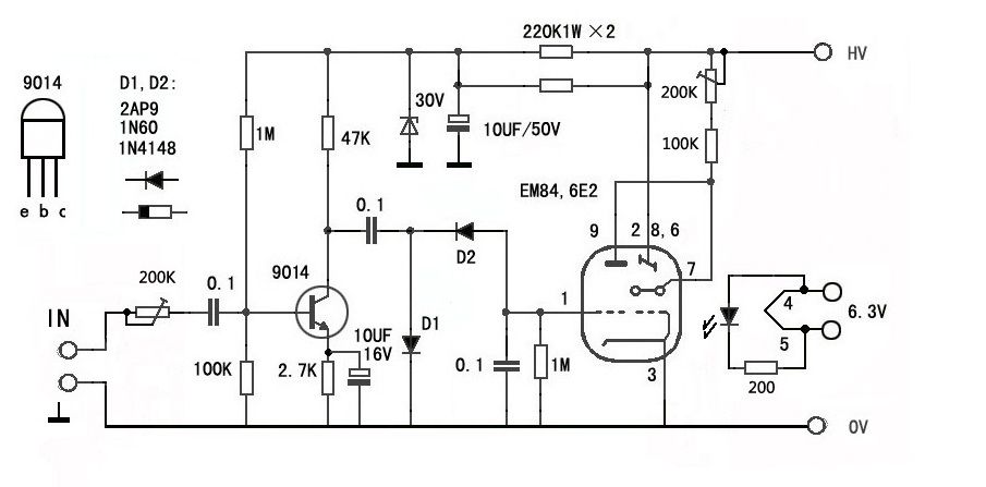
The plate has dimensions of 73x40mm and was made as double-sided. Below is a diagram and a list of elements;
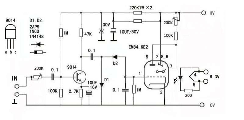 o Resistor 220k? / 1W 2 pcs.
o 100k? / 1W resistor
o Resistor 1M? / 0.25W 2pcs
o 100k? / 0.25W resistor
o 47k? / 0.25W resistor
o 2.7k? / 0.25W resistor
o 200? / 0.25W resistor
o 10 uF / 50V electrolytic capacitor
o 10u / 16V electrolytic capacitor
o Film capacitor 100nF / 100V 3 pcs.
o 200k assembly potentiometer 2 pcs.
o Universal silicon diode 2AP9, 1N60, 1N4148 etc. (in the presented set these are 1N4148) 2 pcs.
o Zener diode 30V / 1,3W
o Blue LED (!)
o SS9014 NPN transistor
o Double ARK connector 2 pcs.
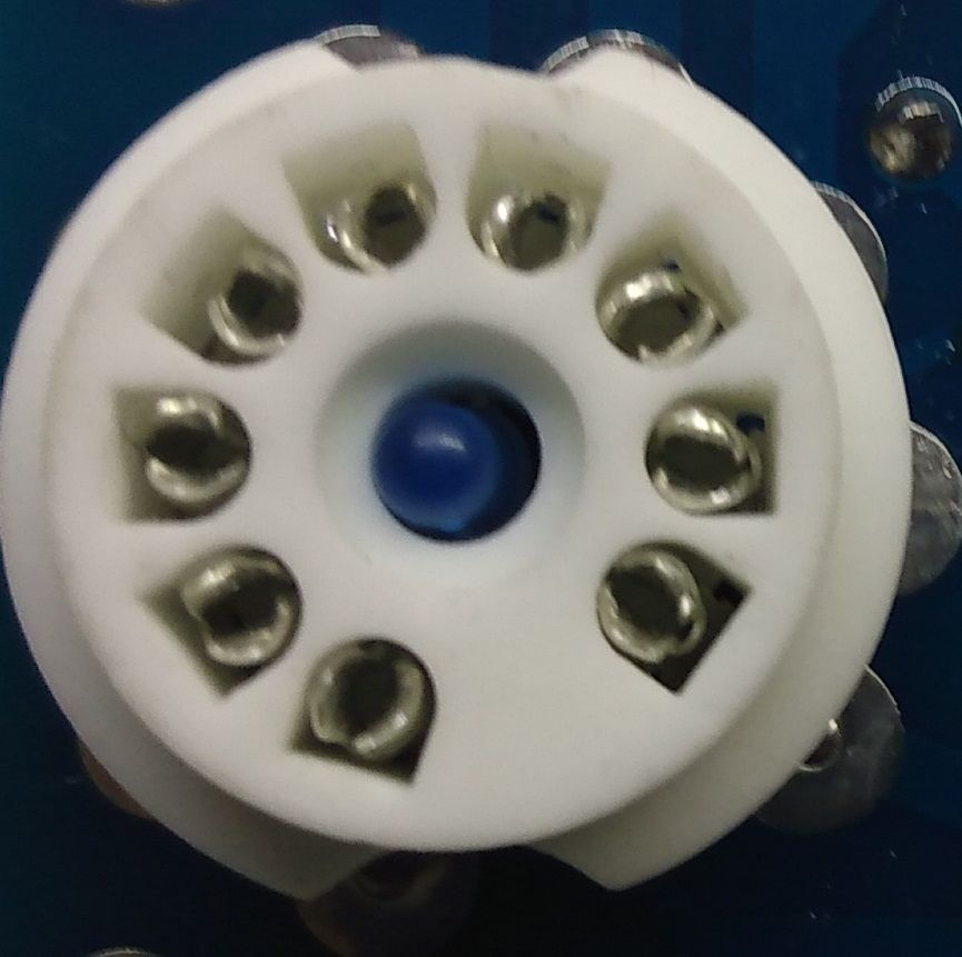
o Lamp stand
o Magic eye 6E2 lamp
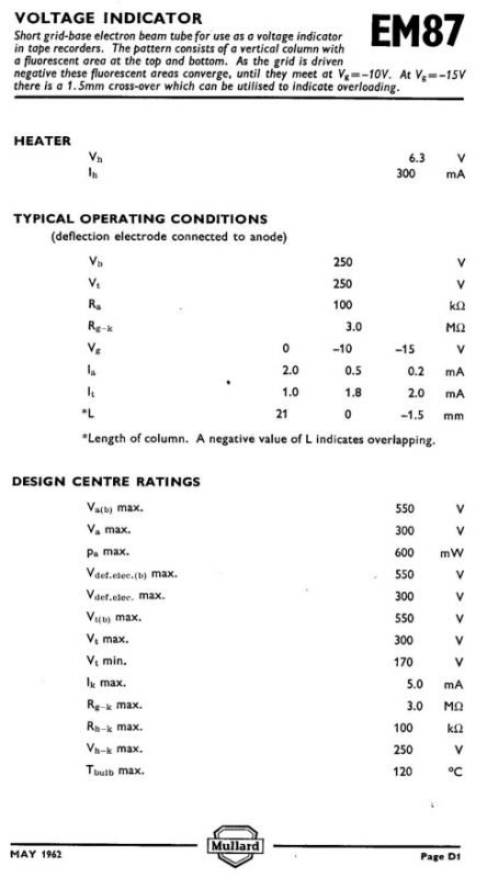
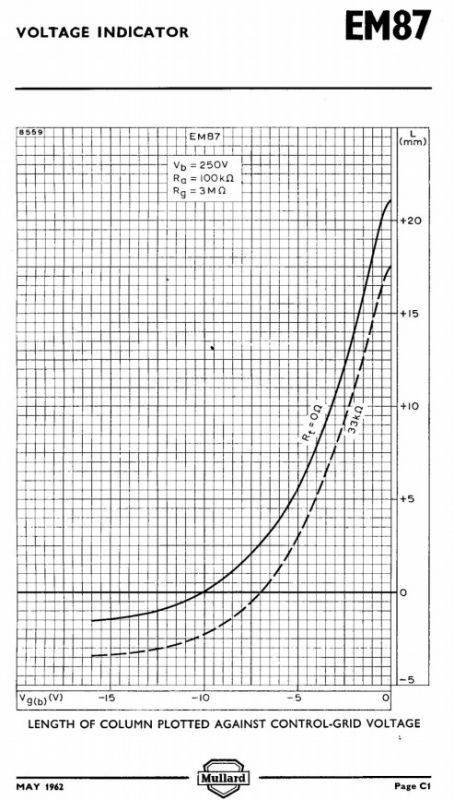
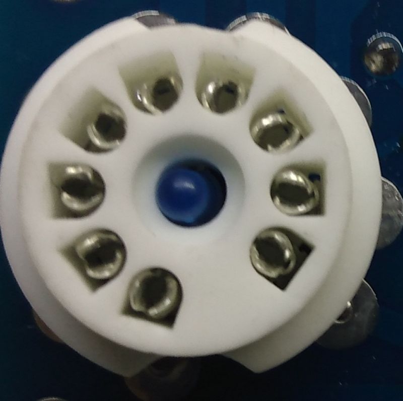
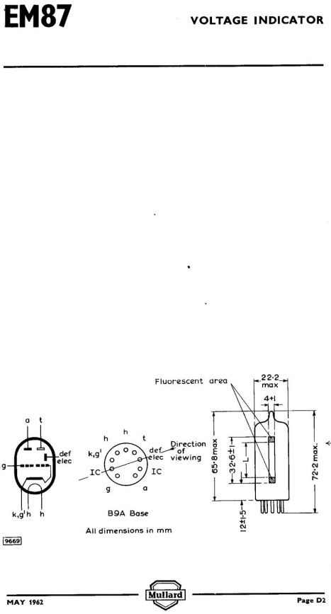
o Double-sided PCB with metallization Of course, as in most Far East tube kits, the designer placed a blue LED in the hole in the lamp's base, making it more beautiful. The blue glow in the lamp's bulb is bad for it and signals the deterioration of the vacuum. I was surprised by the stand itself, which is made of real ceramics, not cheap plastic. After a short search for the lamp itself, it turned out that the 6E2 is a replacement for the EM87 produced by the now defunct English company Mullard. Below is a scan of the original Mullard catalog note;

So let's deal with the assembly of the putty to be able to look at
Magic eye (or rather, in the case of the 6E2 in a strip

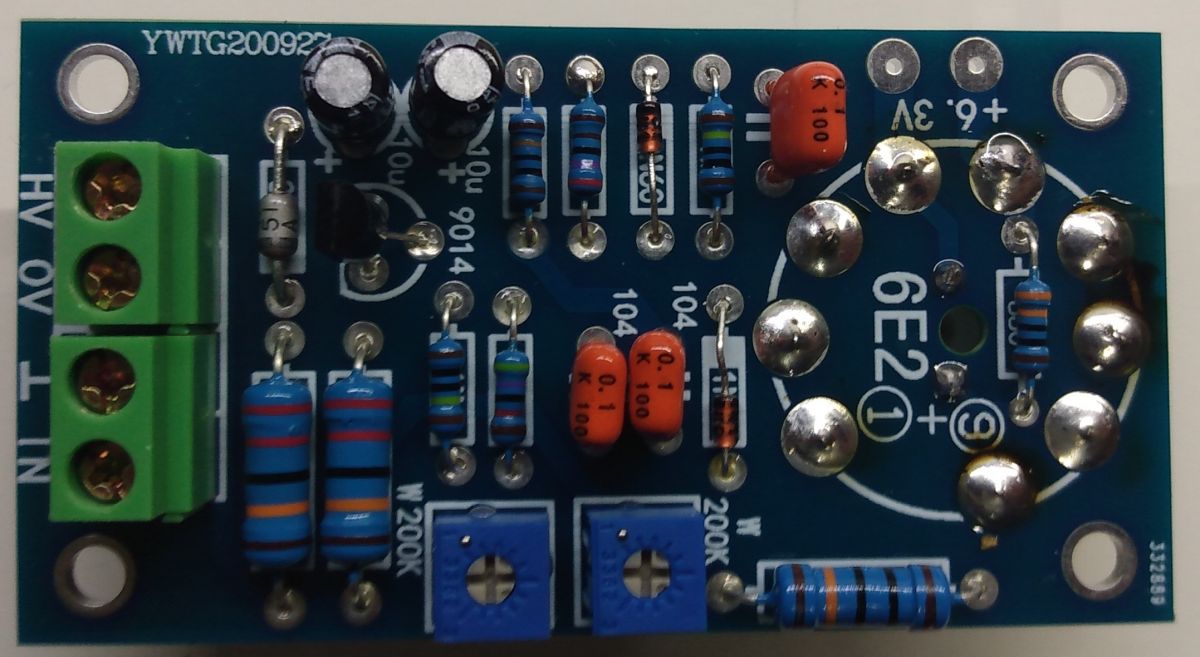
). It is convenient to start the assembly with the lowest elements, which are universal diodes and the zener diode. Let's remember about the polarization of the elements that require it!
And the whole thing;
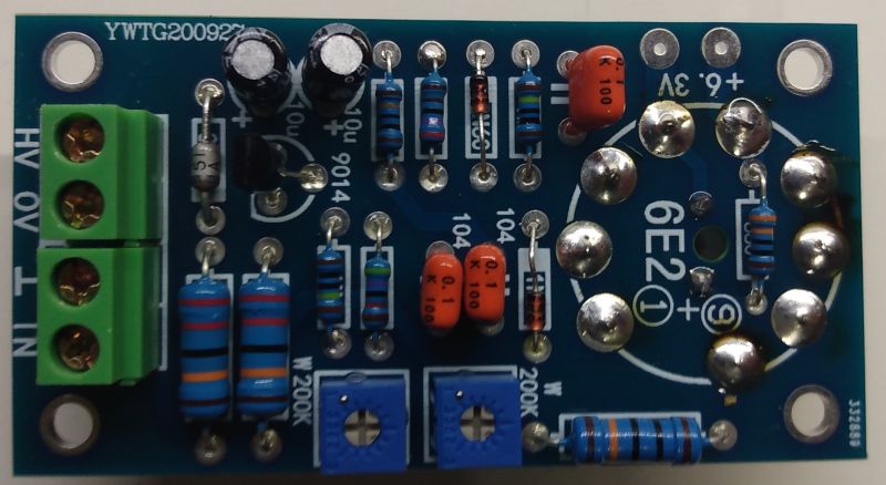
The lamp socket should be mounted on the opposite side than other elements and the LED should be inserted beforehand, because after soldering the socket, hitting the LEDs in the holes will be impossible;
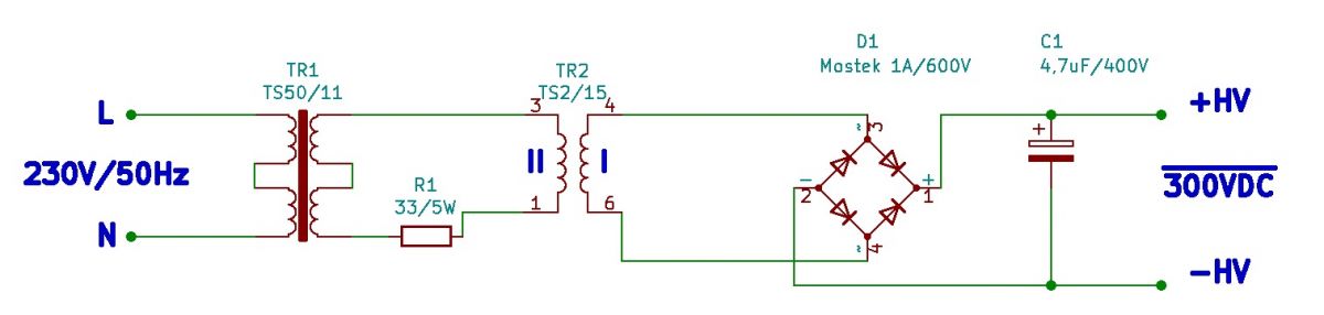
The kit is basically ready to run and as long as there is no problem with a voltage of 6.3VDC (one of the workshop power supplies will provide), where to get 250-300VDC? It would be very problematic to construct a suitable converter for me, especially for almost one-time use, but I have a whole box of various network transformers. So I used the TS50 / 11 from OTV Vela as the main transformer and TS2 / 15 as the step up transformer where the windings are connected the other way round. The output voltage is about 330V without load and after connecting the indicator plate it drops to about 250V. Below is a diagram;
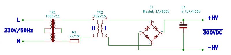
The values of the elements were not calculated in any way and the system was only to provide a voltage of about 300V for several minutes. I connected the glow from a regulated power supply. The effect is really beautiful, although the movie does not fully reflect it due to the automatic operation.
Recordings in a slightly dimmed room and visible cutters kept the module in the correct position, with the LED below;
[movie: e0d4537db4]
https://filmy.elektroda.pl/23_1623168896.mp4 [/ movie: e0d4537db4]
And after cutting the current-limiting resistor for the diode;
[movie: e0d4537db4]
https://filmy.elektroda.pl/22_1623169035.mp4 [/ movie: e0d4537db4]
The fact that the potentiometers and the lamp are placed on the opposite sides of the PCB is a bit disturbing, it requires various manipulations to adjust the putty. The potentiometer in the anode line of the lamp adjusts the length of the "strip" and the second set the sensitivity (about 1V RMS for full lighting). The lamp itself heats up quite a bit and it should be remembered when installing the putty in the housing. It is worth buying the indicator kit in duplicate, which will allow you to work with a stereo signal. In the case of tube amplifiers, the connection will be very simple, and in the case of transistor amplifiers or on integrated circuits, after adding the appropriate power supply, the indicator will add a little tube charm to the design ... (although the sound will not change, unfortunately).


Comments
Well, now it's time for some plasma VU indicator, e.g. one from SSL or Neve consoles, I wonder what it has inside, I have always been curious about it :-) Sometimes you can get it at auctions somewhere,... [Read more]
Such an indicator would look good in a metal tube with an elliptical cutout for a phosphor, but the plate forces a large base for such an indicator. In the final application, a small size DC / DC converter... [Read more]
I can measure how many mA "pulls" at these 250V, although TS2 / 15 after about 15 minutes had a temperature of about 40 degrees C which proves that these 2W is not enough. [Read more]
The visual effect is interesting - I mean "snapping" the straps. For those who don't want to play with high voltages, something like this could be simulated on an OLED display. [Read more]
The stripes can overlap and then shine very brightly, even in DS this is written as an overload function. [Read more]
On the well-known Chinese portal, you can purchase a 6E2 power module on the MC34063 chip. Power supply of the module from 9-12V. The output voltage is max. 350V with a current consumption of 4mA, and... [Read more]
The lamp itself has little power needs, the vast majority is absorbed by the 30V stabilizer. [Read more]
Hello! I also have these eyelets, I bought them on Allegro, used the SE amplifier on EL84 and 6N2P. The 6E2 lamp is a replacement for the EM87, but the EM84 / 6E3P works equally well in this system,... [Read more]
I keep wondering why they keep getting tired of 34063, instead of using UC3843 as a human. These high voltage converters on the ne555 / 34063 come in bundles for a variety of applications. [Read more]
Hello It is enough to use a high-voltage transistor, e.g. the famous MPSA42, then you can get rid of the zener diode. You can also use a small vacuum tube, e.g. EF95 (6AK5) or non-microphone EF86. ... [Read more]
@ mercury bulb you quoted not my words. [Read more]
The UC3843 has from 8.5V, so for those 9-12V it would work without any problems. However, there is now a new series of these systems, including one that starts from 7V. UCC38C41 In any case, if we... [Read more]
QUOTE: .... The fact that the potentiometers and the lamp are placed on the opposite sides of the PCB is a bit disturbing, it requires various manipulations to adjust the putty. The potentiometer in the... [Read more]
Hello! The EM34 is .... EM4 with an octal pedestal. Both lamps very rare, sought after and damn expensive, even on E-Bay. I have a Nornan LV1220 radio with EM34, the receiver from 1952, after replacing... [Read more]
Thanks, I had an EM4 shock - PLN 220 on All ..... I'm converting to 6E5S. I have a. ps As for the diagram from the first post. That blue LED backlight. With the alternating voltage of 6.3V, you would... [Read more]
Apart from technical matters, this blue LED should not be there at all. It spoils the whole "aura" of the lamp. [Read more]
Did you use any particular audio input? I put the audio signal on my module and the scale, unfortunately, does not budge. Do you have any suggestions? https://obrazki.elektroda.pl/1868136000_16424... [Read more]
I was feeding the signal from the line output of the monitor. [Read more]
Hello! You can have a rammed transistor or badly soldered 1N4148 diodes. And so, out of curiosity, I will ask: What is this inverter next to it? How much load does it have, will it pull two such lamps... [Read more]