 Hello.
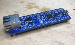
I will present here my own little project, the Fubarino-Eth board offering USB and Ethernet connectivity based on the 32-bit PIC32MX795F512H (512KB Flash, 128KB RAM) and the famous ENC28J60. This board is my version of the famous Fubarino-SD 1.5 from
fubarino.org / schmalzhaus . I reworked this board a bit and prepared example projects for it in MPLAB X with XC32 and Mikro C Pro for PIC32. The project was designed to create a platform offering both USB and Ethernet connectivity, while maintaining the ease of connection to the breadboard. This board is compatible with the original Fubarino and is also supported by the Arduino IDE environment (by hipkit / mpide module) with USB bootloader.
Board design
This project is my reworked version of the so-called Fubarino SD about which you can read here:
https://wiki.seeedstudio.com/Fubarino_SD/
https://github.com/fubarino/fubarino.github.com
I attached the documentation of Fubarino SD below:
Fubarino_S..v14.zip (606.68 kB)You must be logged in to download this attachment.
fubarino-1...4eagle.zip (1.5 MB)You must be logged in to download this attachment.
Fubarinov1...5eagle.zip (2.72 MB)You must be logged in to download this attachment.
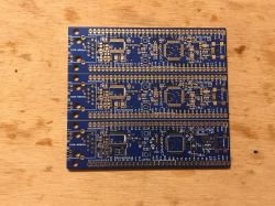
My version, Fubarino-Eth, puts more emphasis on connectivity and gives up the microSD card slot and in its place offers Ethernet connectivity via ENC28J60:
My version is also much longer, but it does not exceed the magic limit of 100mm so that you can still order a bare PCB cheaply from the Chinese PCB manufacturer (most tile mills have the smallest bid up to 10cm by 10cm, and then the price goes up).
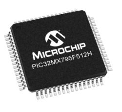
The board (original and my version) is based on PIC32MX795F512H:
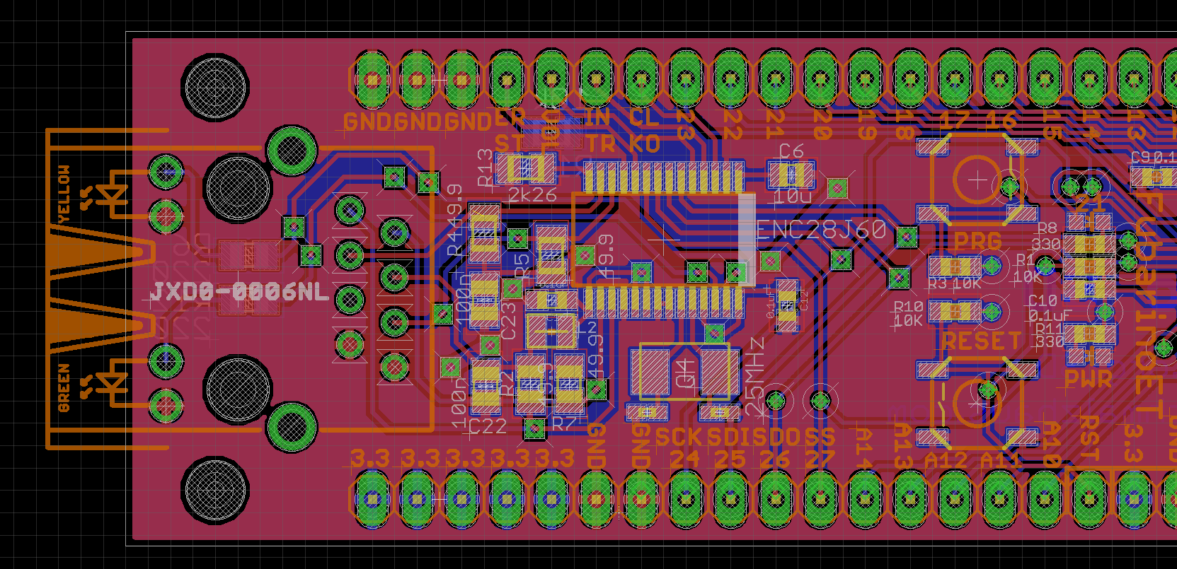
Here's a look at what I've added, which is the Ethernet connectivity section:
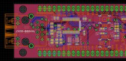
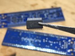
ENC28J60 is housed in a small SSOP28 case, bigger case would not fit:

ENC28J60 is also available in QFN, but I did not want to make soldering even more difficult, because the project is made on the assumption that it can be soldered at home (yes, it is possible to solder TQFP without hot air, I soldered three pieces of Fubarino-Eth so far).
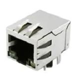
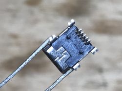
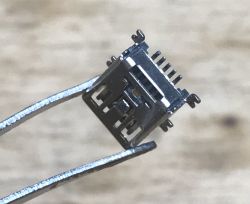
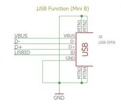
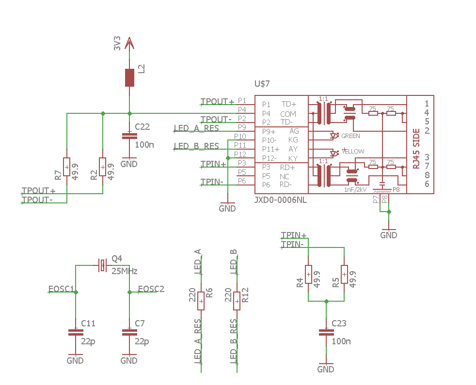
The Ethernet/magjack connector used is JXD0-0006NL:
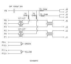
Here is JXD0-0006NL internal diagram. An isolation transformer is integrated in this connector, this is why it's called 'magjack'. This integration reduces the number of components on the PCB:
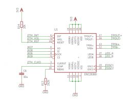
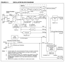
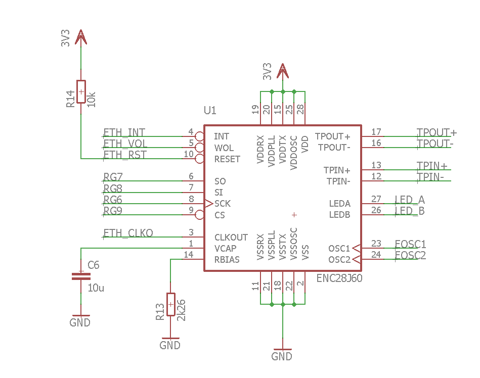
This is the whole diagram of the Ethernet section I added, part 1, ENC28J600:
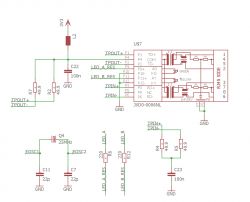
Part 2, JXD0-0006NL and the rest:
The connection diagram of the PIC32MX795F512H (or equivalent) has remained unchanged from the original (Fubarino SD), so I will not include it here.
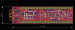
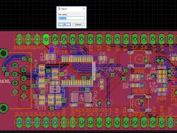
Full schematic of my version in .sch (Eagle) format and board in .brd:
Fubarino-1...oSd-15.zip (89.1 kB)You must be logged in to download this attachment.
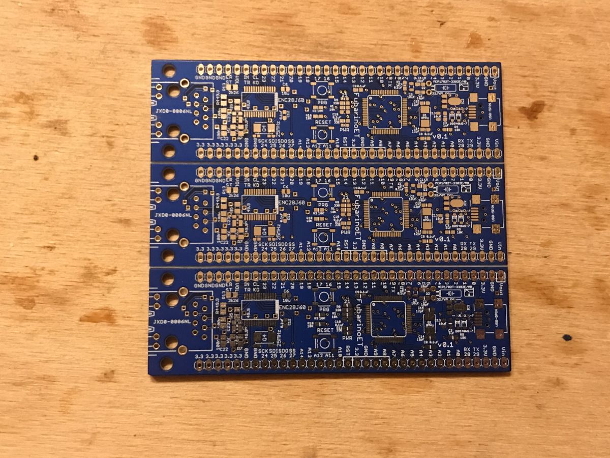
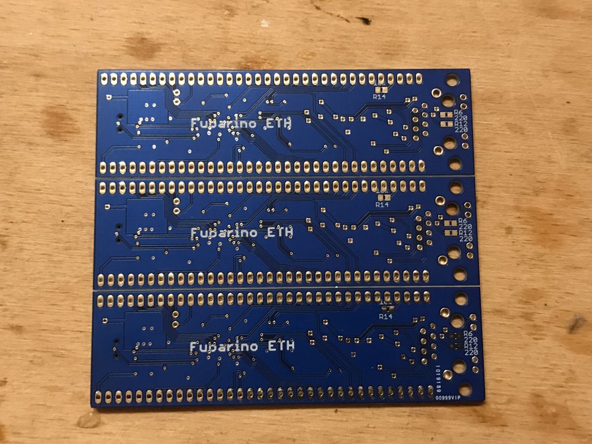
Below the Gerberas of the panel, 3 tiles per panel (the ones I sent to the PCB manufacturer):
Fubarino_E...3_fxed.zip (503.63 kB)You must be logged in to download this attachment.
Soldering the board - the beginning
This time, the selected PCB manufacturer did not request additional payment for the panel (as long as one PCB design is repeated in the panel), so basically I bought 5 panels with 3 PCBs (15 boards total).

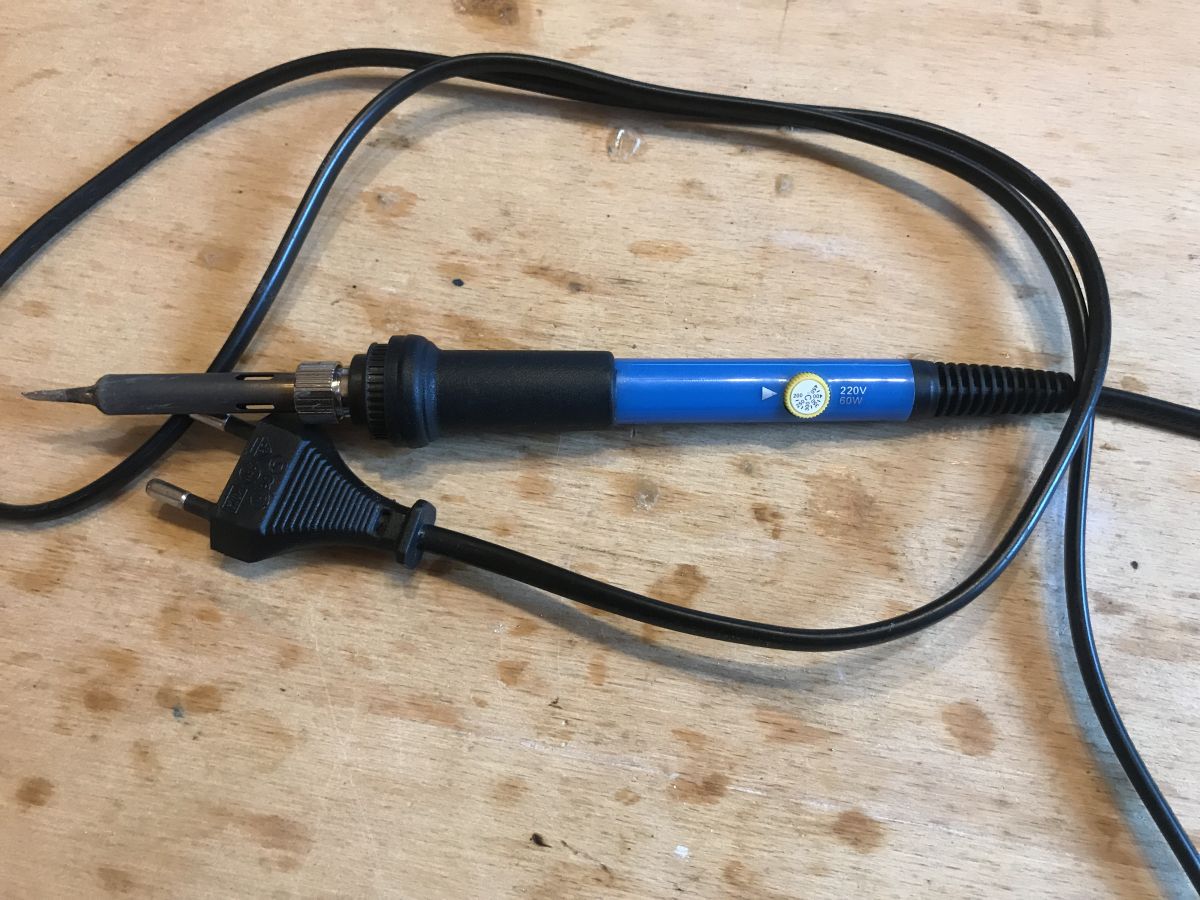
For soldering, I use the cheapest soldering iron with power regulation:

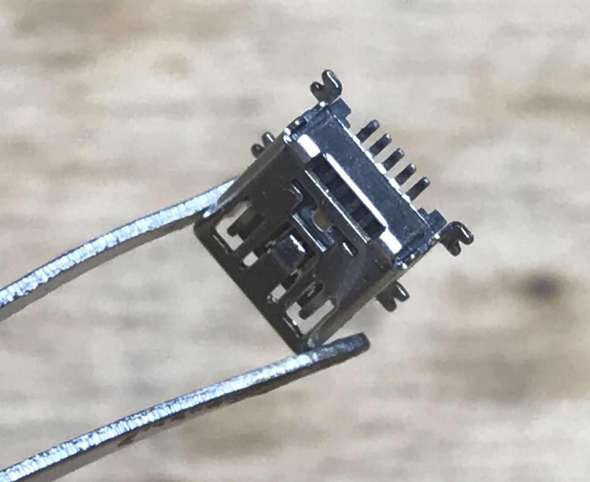
I started with the most difficult parts. Mini USB and PIC connector:
Mini USB connector. I use the one with two plastic protrusions on purpose because it sticks well and solders well:
It is a connector with an additional USB ID pin (OTG, On-The-Go standard), needed to be able to choose whether the device is a host or a slave.
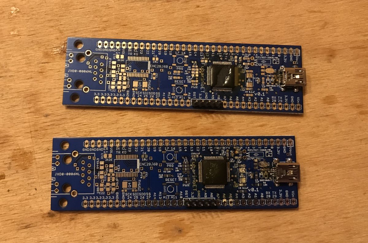
 I soldered the necessary minimum in three versions:
- PIC32MX575F512H
- PIC32MX675F512H
- PIC32MX795F512H
Their conclusions are compatible, so there was no problem.
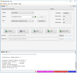
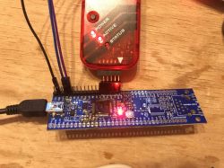
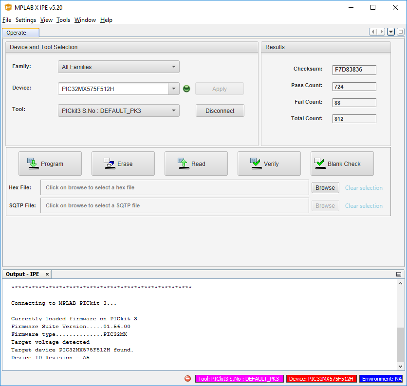
Then I checked if the programmer can see the microntroler. PICKIT3 (via MPLAB IPE) detects PIC32MX575F512H:
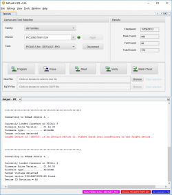
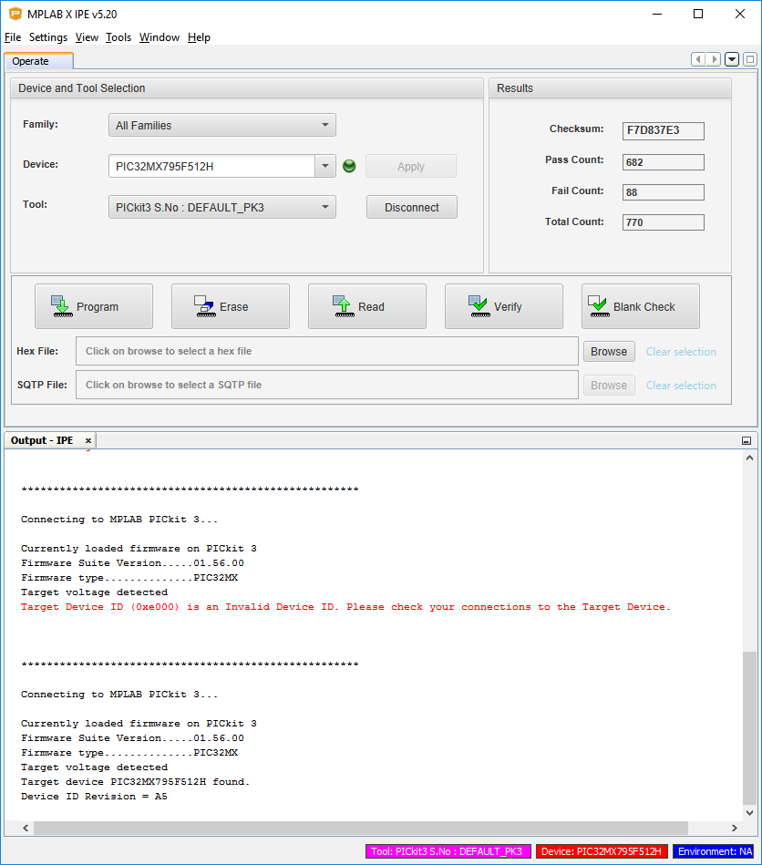
PICKIT3 (via MPLAB IPE) also detects PIC32MX795F512H:
 Minor fix
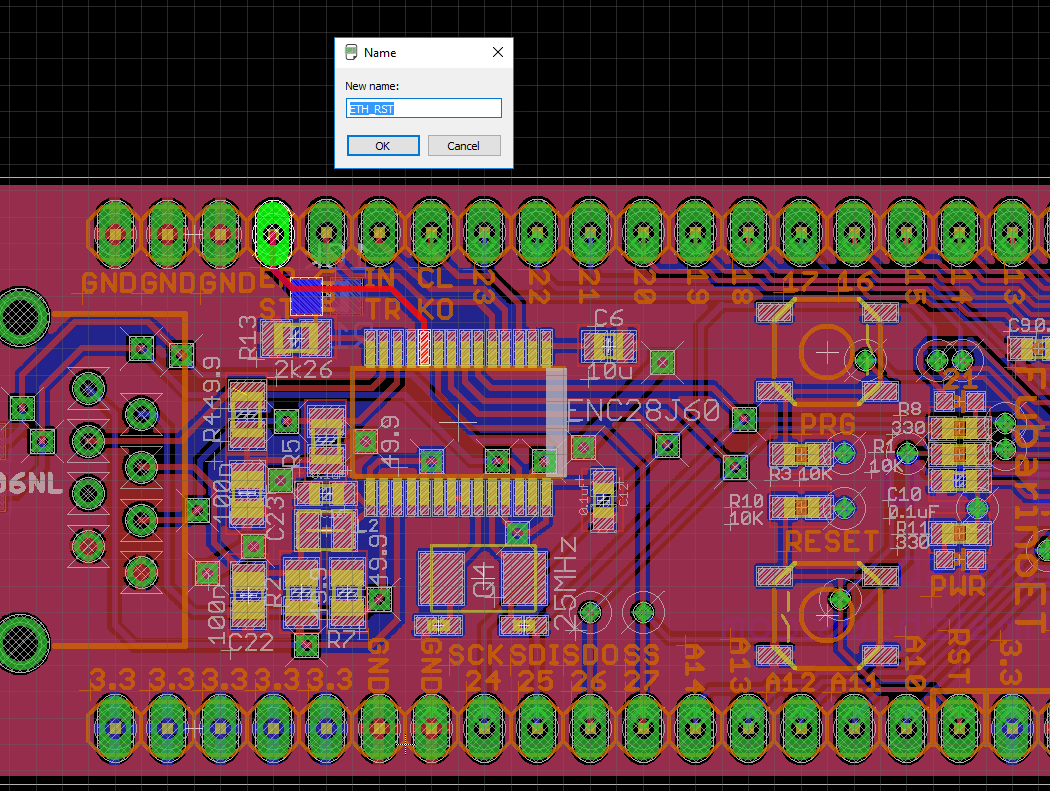
Unfortunately, I missed one thing when designing the tile. I did not connect the RESET pin from ENC28J60 to one of the PIC pins. I fixed it afterwards by adding a jumper (not a problem), but it is worth noting that there was such a problem.
 Test program - blink, button, UART, USB
I have prepared the test program to facilitate the verification of solders on the board. I made it in MPLAB X (XC32 compiler) based on "HID Keyboard" example from Microchip. This program sequentially checks the basic functionalities of the board (without Ethernet) so that I can quickly determine if everything is ok.
This program requires soldering:
- power block (USB connector, 3.3V LDO regulator)
- microcontroller with the necessary elements (RESET resistor, 100nF capacitors, VCAP capacitor)
- 8MHz quartz resonator
- PRG LEDs
- PRG button
Additionally, you need to connect the USB UART converter to the RX / TX pins from UART2.
This program in turn:
- LED (RE5) blinks several times
- sends messages to the UART
- creates a keyboard HID device
- waits for the PRG button on the RE7 to be pressed and sends the next letter with each press, pretending to be the keyboard
Example short code:
Keyboard handling code (key press send by HID):
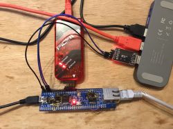
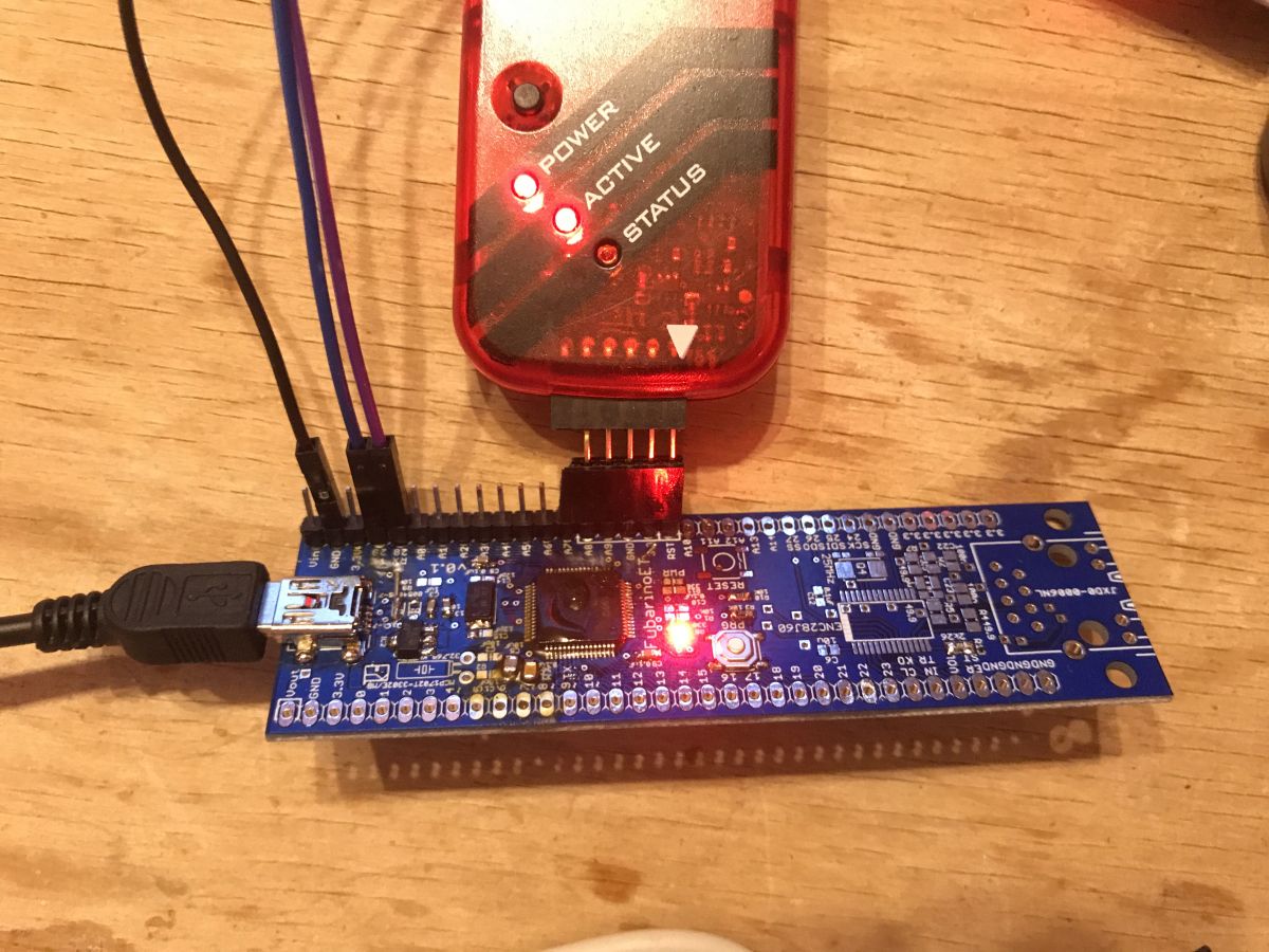
Fubarino-Eth testing setup:
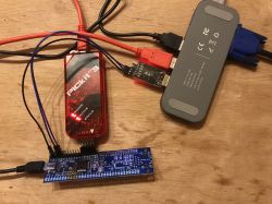
Here you can see the programmer tool I use, PICKIT3, the USB-UART converter, and power and USB conncetions. Everything on my Blitzwolf hub (including the VGA monitor).
PIC32MX on Fubarino board is powered by 3.3V LDO from USB 5V.
By the way, the MPIDE options "power target circuit from tool" didn't work for me in this case. Somehow I couldn't ever get this feature running. Powering circuit from tool always worked for me on PICKIT2, but on PK3 it seems broken. I'm not sure if it's a common issue or the fault of my PK3.
Basic test - blink LED:
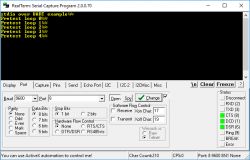
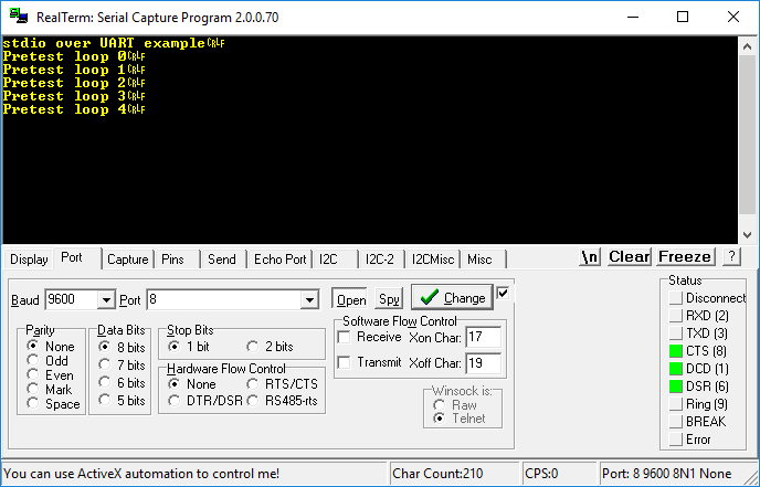
Second testing stage - UART:
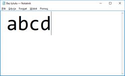
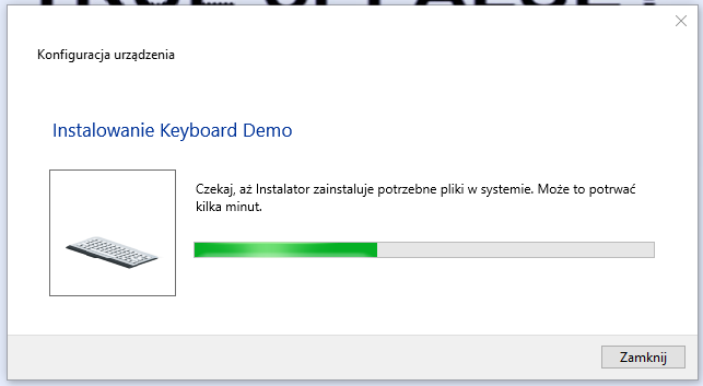
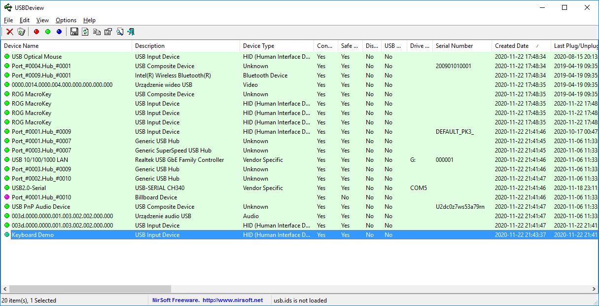
Third test stage - computer should recognize USB device (HID keyboard):
USB Dev View:
Test stage 4 - now, pressing a Fubarino board button sends a HID letter presses to PC:
Full example project for download (based on Microchip repository HID demo)
MicrochipM...inoETH.zip (916.82 kB)You must be logged in to download this attachment.
Example 2 - blink, UART, Ethernet
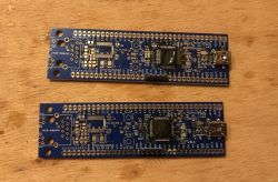
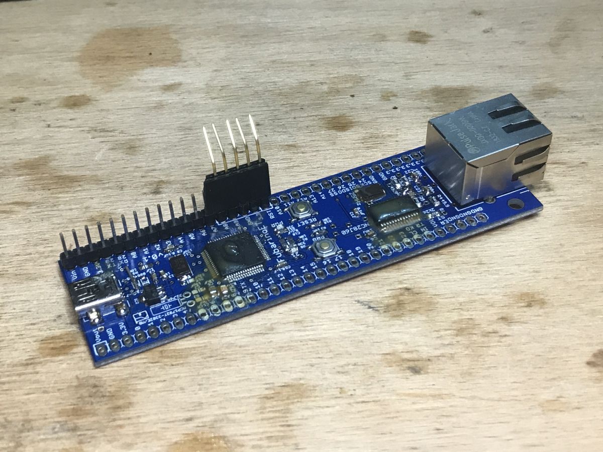
Next I soldered remaining parts of the circuit (ENC28J60 and magjack). Here you can see ENC28J60 in SSOP28 case (called ENC28J60/SS):
Ready circuit:

I prepared a second example project to make Ethernet testing easier. This time I chosen to use another IDE - Mikro C PRO for PIC32. I already had some Ethernet library code ready in this IDE (I used it for PIC32MX250F128B in the past) so I decided to port it for Fubarino Eth. Both PIC32MX250F128B and PIC32MX795F512H are similiar so porting is easy.
This example project requires ENC28J60 block soldered correctly (with 25MHz crystal and magjack), also you need to connect to your router to test it:
Some code snippets from example:
The TCP handler function:
After running the example, first the LED blinks and then you can see some UART messages:
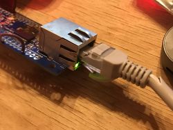
Then the Ethernet module starts and MagJack LED lights up (one indicating sending, second receiving):
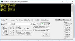
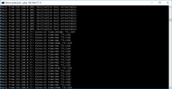
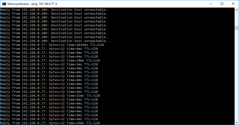
Then you can ping board (commend: ping 192.168.0.77 /t, switch /t causes it to ping repeatedly):
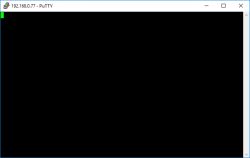
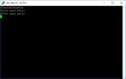
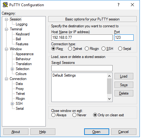
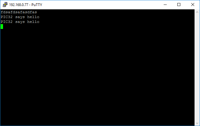
Finally, you can connect to PIC by TCP (for example, by using Putty) and receive 'hello world' message:

So here I attach full example, MikroC project configured for PIC 575 (not 975!):
PIC32MX575...TCP_SV.zip (382.19 kB)You must be logged in to download this attachment.
Example 3 - HID communication
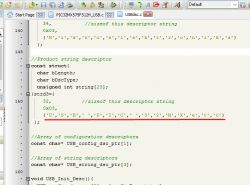
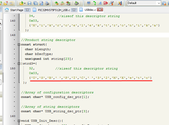
This example will use Mikro C dla PIC32. Mikro C has already built-in HID libraries for USB, what makes development easier. Most of the HID code is hidden from user and programming HID applications is faster this way. Making of Hello World HID requires basically only attaching USB HID descriptor file and the following code in your main C file:
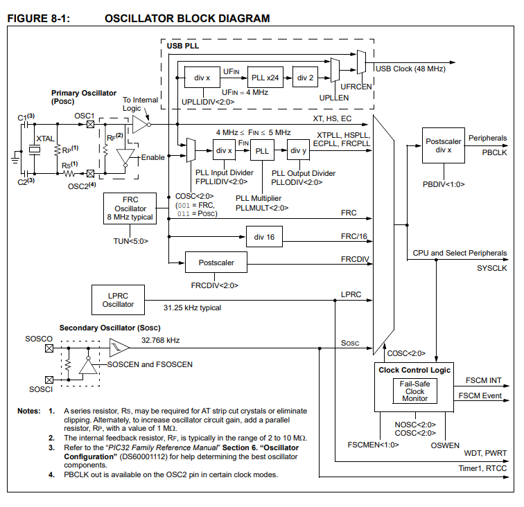
Of course you also must have correct Configuration Bits, correct PLL and crystal. You have to respect clock requirements from datasheet, eg. UFin must be 4MHz, and USB clock must be 48MHz (you must choose div/PLL correctly):
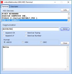
My USB device is called "PIC32 mxetc":
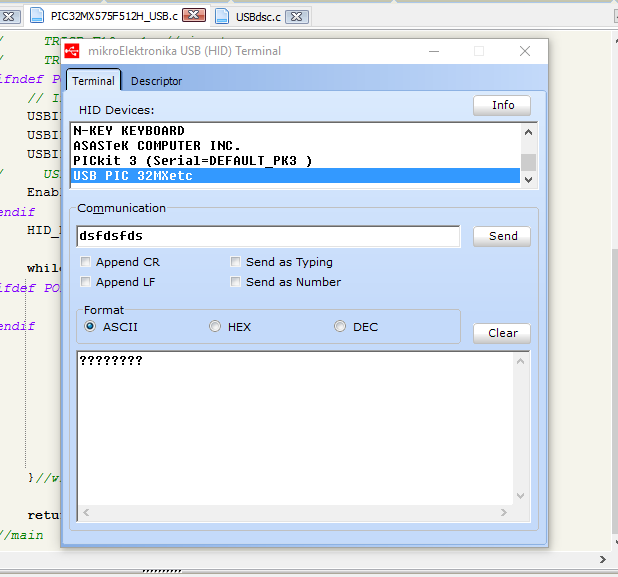
After burning the firmware with PICKIT and connecting the board to PC:
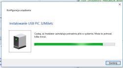
As you can see, PC detects device without any issues, you don't need to have any special drivers for HID.
For testing HID, you can use HID Terminal from Mikro C:
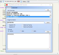
PIC can reply to HID packets:
The following example can be easily modified to act as HID mouse, keyboard or game pad.
Here you can download full MikroC project for PIC 575 (not 975!):
PIC32MX575...SB-hid.zip (221.55 kB)You must be logged in to download this attachment.
Fubarino-Eth and Arduino IDE
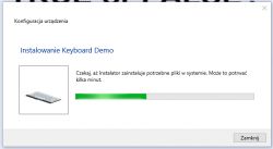
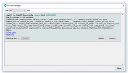
My Fubarino-Eth is compatible with Arduino IDE, just like vanilla Fubarino SD. In order to use Arduino IDE with Fubarino, first you must add the Chipkit/MPIde support by "Boards Manager". Also you must have the Fubarino bootloader burnt onto your PIC, so after soldering your board you must use PICKIT3 or similiar programmer to flash it at least once.
For more information, see Chipkit/MPIDE wiki:
http://chipkit.org/wiki/index.php?title=ChipKIT_Fubarino_SD
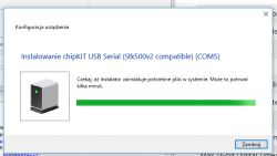
After flashing the bootloader, board is detected as "chipKIT USB Serial (Stk500v2 compatible)":
Bootloader file (the one I used for PIC32MX795F512H):
FUBARINO_S...loader.zip (6.3 kB)You must be logged in to download this attachment.
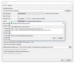
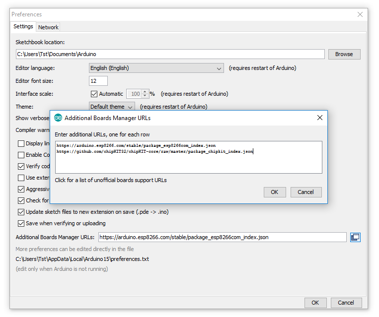
In Arduino IDE, first you should add Github repo link to "Additional Board Manager URLs":
Quote:
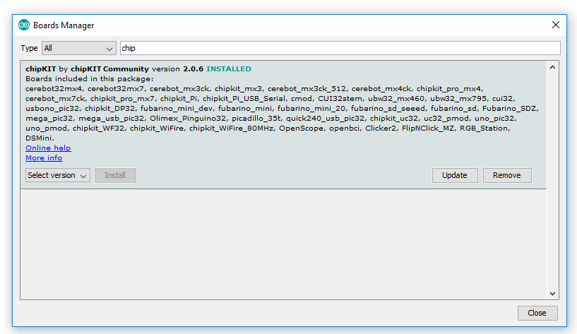
Then you can add board support by Boards Manager. Just search for "chipkit" (this will include PIC32 compiler and Arduino-like libraries):
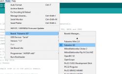
Then, you just have to select which board you have and select programming by "serial" (it's just called serial, but in reality it's USB. It's called serial because USB emulates UART port):
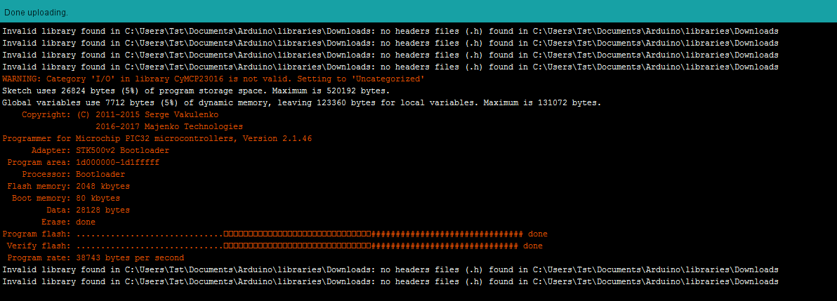
Then, to start programming mode, hold the PRG button and short press the RESET button while still hoding the PRG. Then, first release RESET and then PRG. The red LED on pin 21 should start blinking rapidly. Then, finally, it's time to start upload in Arduino IDE:
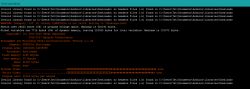
Fubarino-Eth programming by USB bootloader success!:
 Summary
I am very happy with my project. It's more educational and satisfying to solder my boards myself than to just buy them in the shop.
Soon I might create a newer, better version of my Eth Fubarino fork, this time replacing ENC28J60 with some better chip. Maybe something with RMII interface?
Of course I realize that it also would be possible to create a just Ethernet + something shield for vanilla Fubarino SD, but I didn't have any SD's at hand and I didn't need to have SD card support for the projects I plan so I decided to go along with my version.
The board is very easy to use. RESET and PRG buttons are now almost the the center of board but that's not the issue for me. The only thing more I think I could change in new version is the LDO regulator to increase the current capability of 3.3V source. The current little LDO
might get hot too soon while using both ENC28J60 and some extra peripherals connected.
Entire project is open source, so I attach here all board files, example projects, Gerbers, for download


Comments
This year I also liked PIC, just tell me why are you pouring so much flux on the plate? [Read more]
I like Pice too. Cool project because there are no development boards for these processors [Read more]