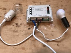
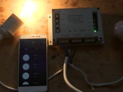
Hello, here I will sho the teardown, detailed photo documentation, PCB analysis and schematic drawing of another Tuya product. This time it will be a controller for 4 relays, pluggable into a DIN rail, controlled as usual via WiFi via a phone application.
Update 2022 - This device is fully supported by OpenBeken. Scroll down to find pin configuration and Home Assistant information
Product purchase
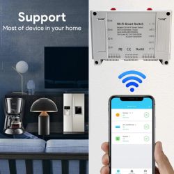
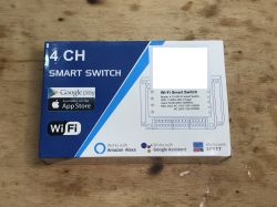
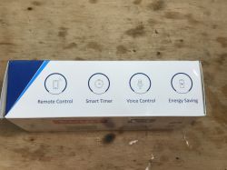
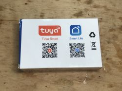
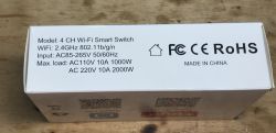
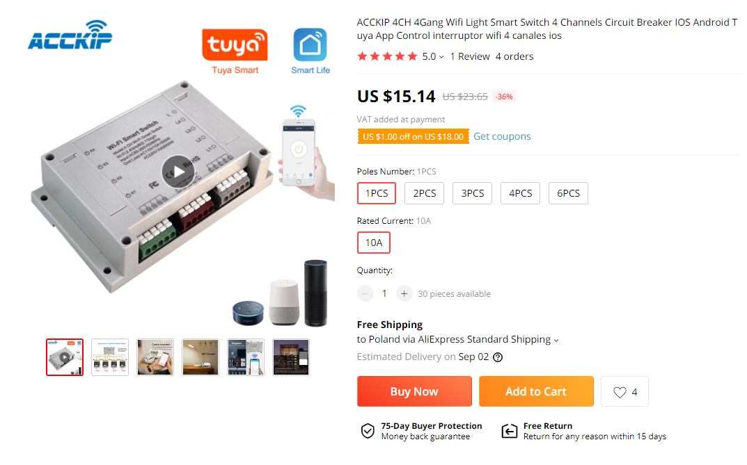
I found the product by searching for "4CH 4Gang Wifi Light Smart Switch 4 Channels Circuit Breaker IOS Android Tuya App Control interruptor wifi 4 canales ios" for about PLN 60 (supposedly in promotion, normally for less than PLN 100). Below are screenshots of the offer:

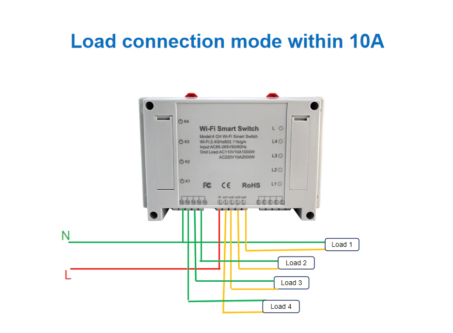
Graphics from the seller:

 Kit contents
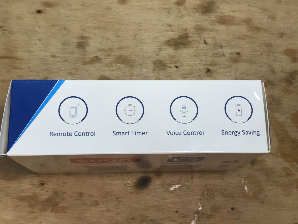
The set includes only a relay and instructions (I censored the seller's sticker because there is no need to do unnecessary advertising):
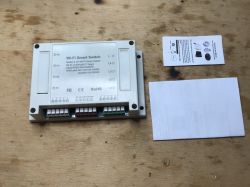
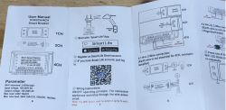
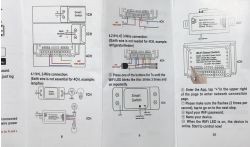
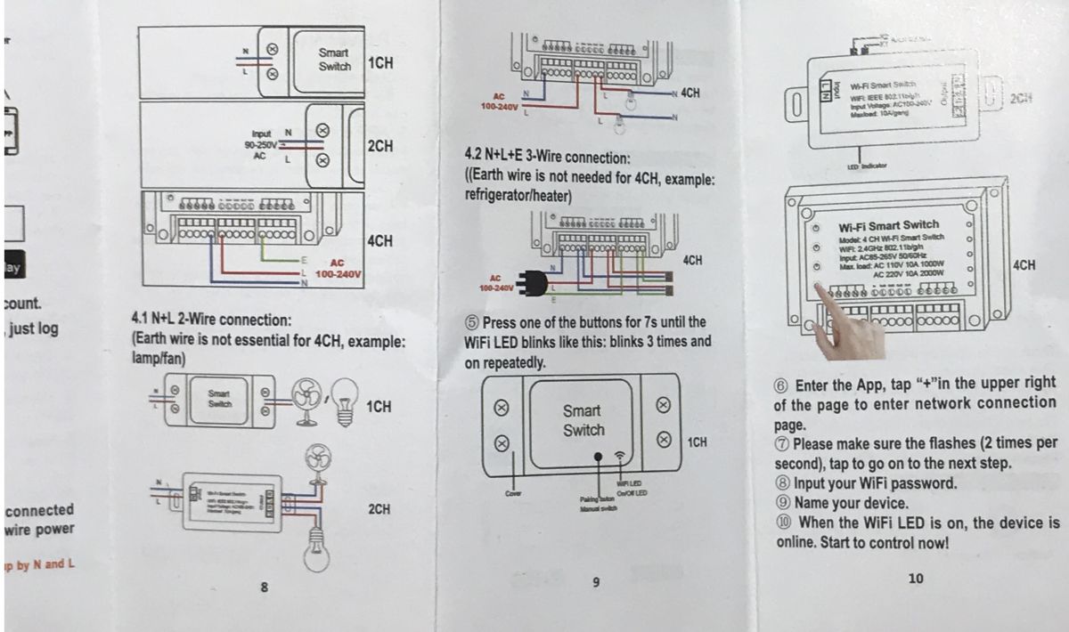
Instruction (information on how to pair with mobile App, etc.):
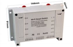
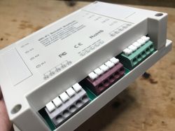
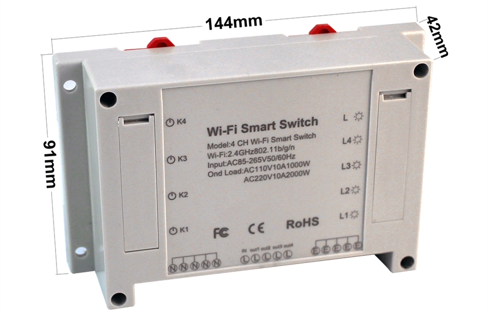
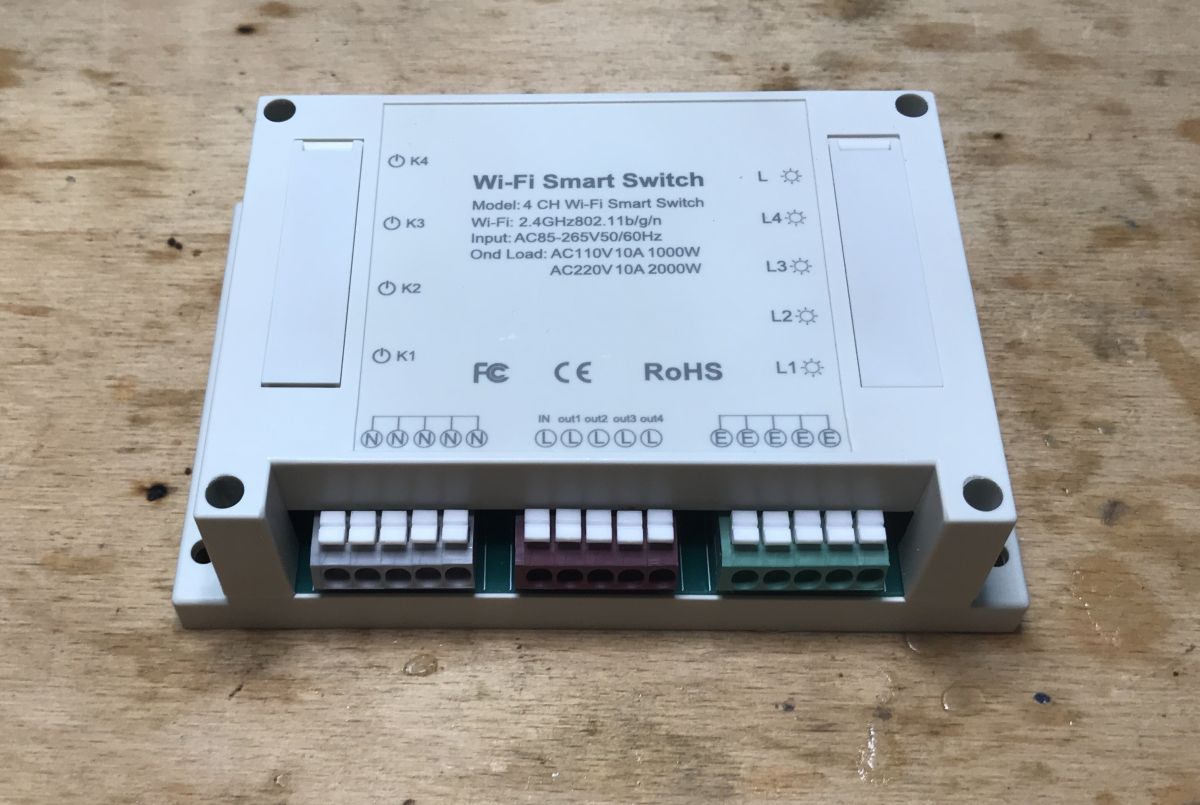
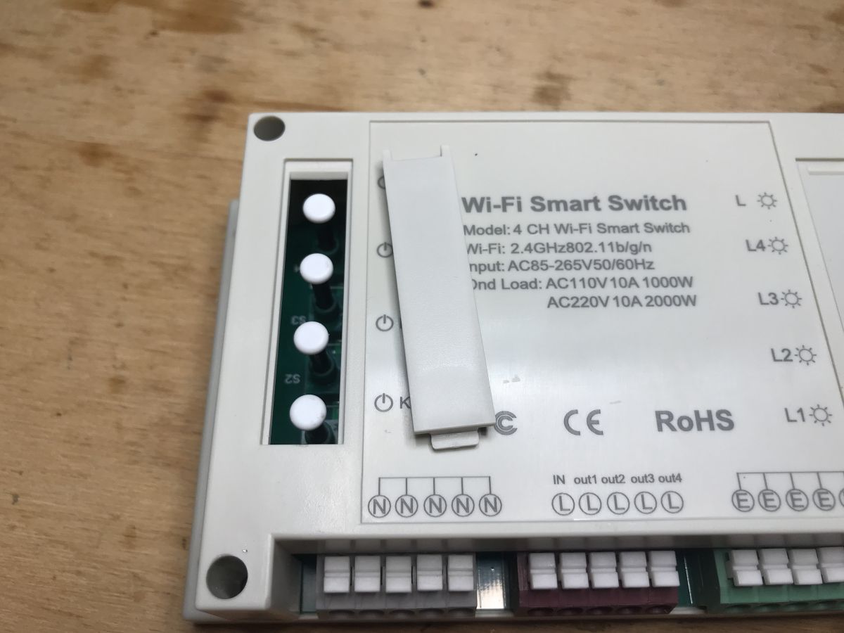
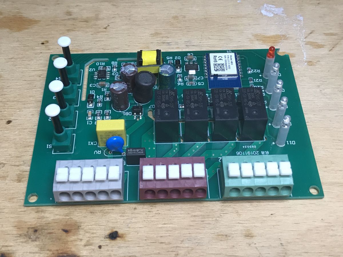
Controller:
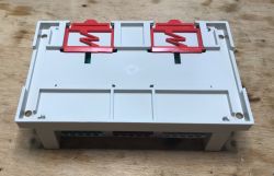
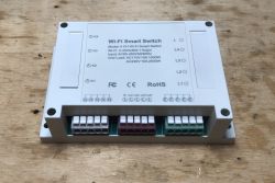
Terminals:
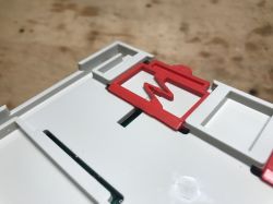
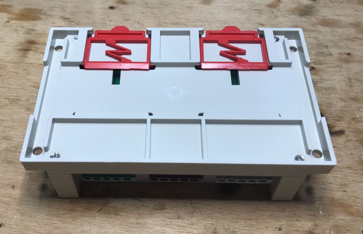
Mounting mechanism on DIN rail:
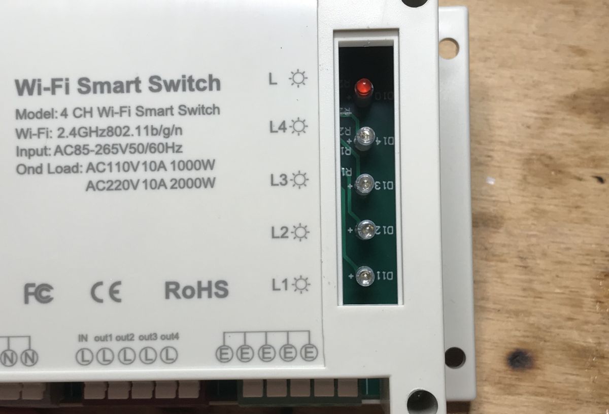
After removing the plugs, you can reveal the buttons and LEDs informing about the status of relays and the device:


I do not know who would like to have these buttons covered, after all, without them, if there is a problem with WiFi, there is no way to control the device.
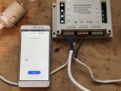
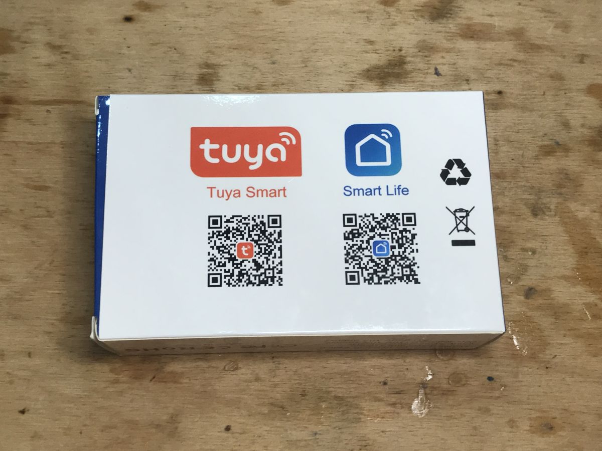
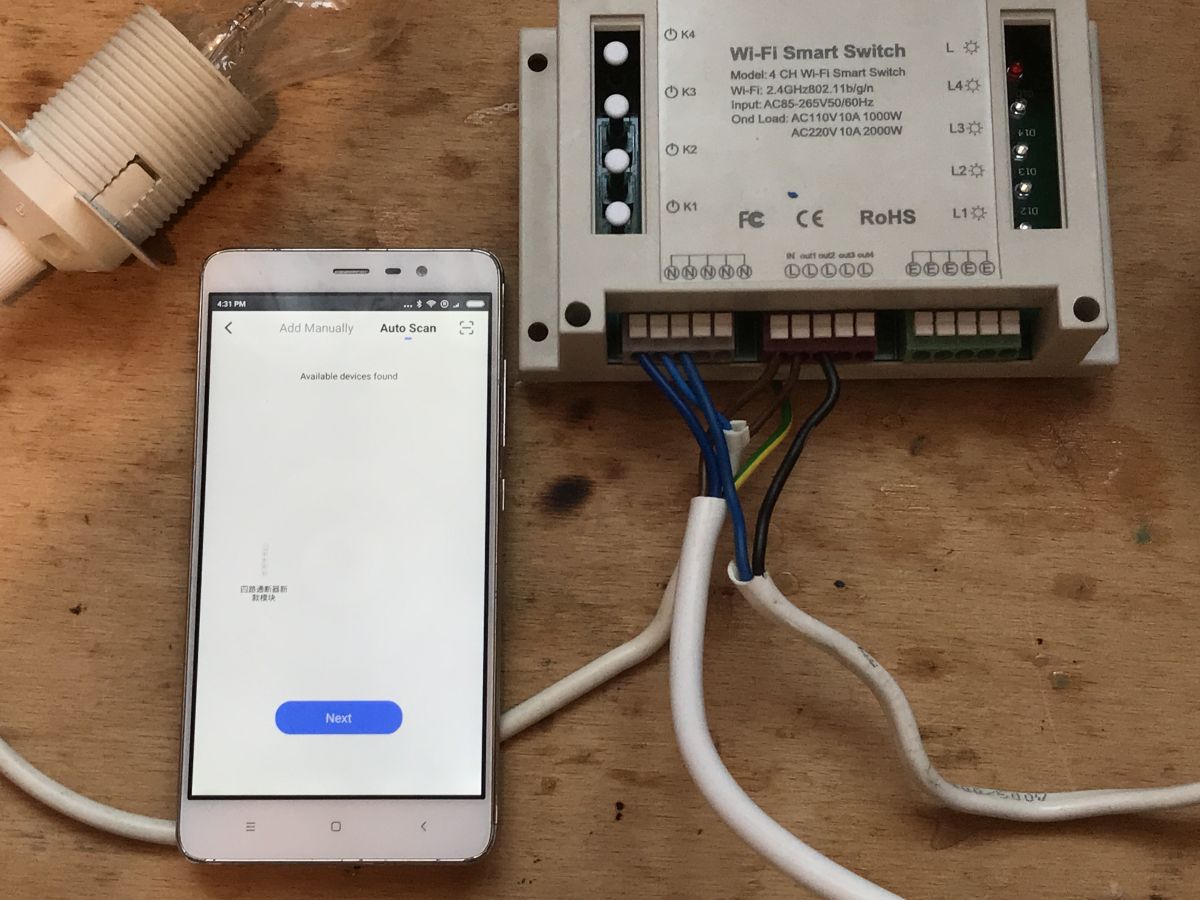
Pairing with original Tuya app
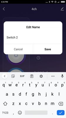
I have covered the pairing with Tuya topic many times in the past. This time it also was very easy, although Chinese characteres appeared as the name of the device.

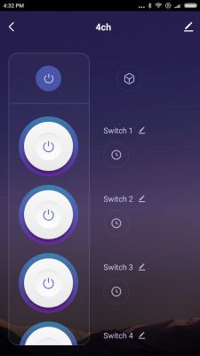
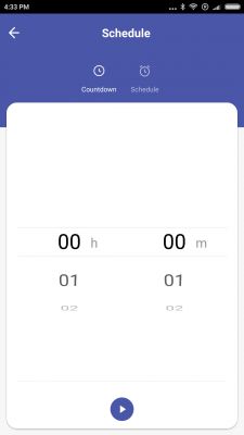
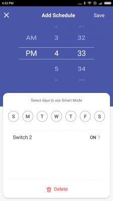
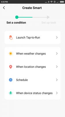
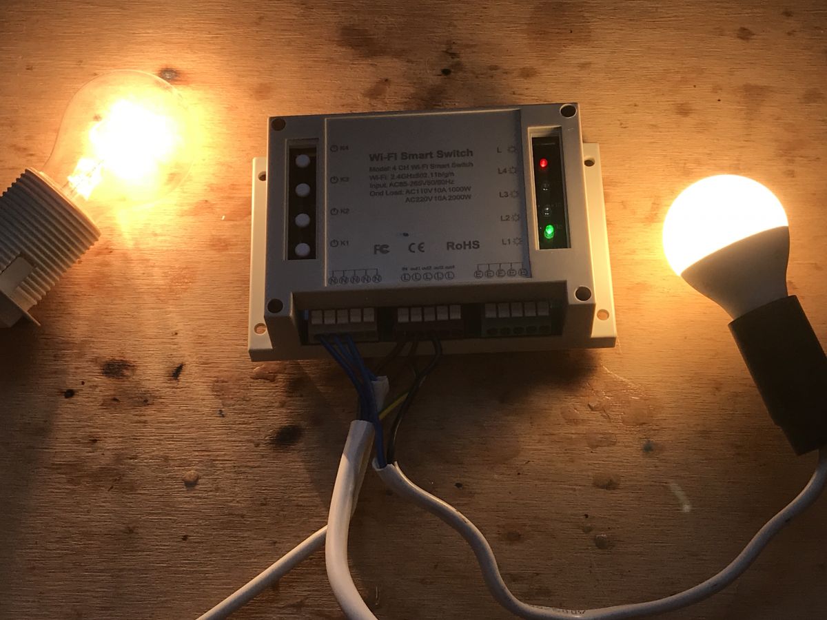
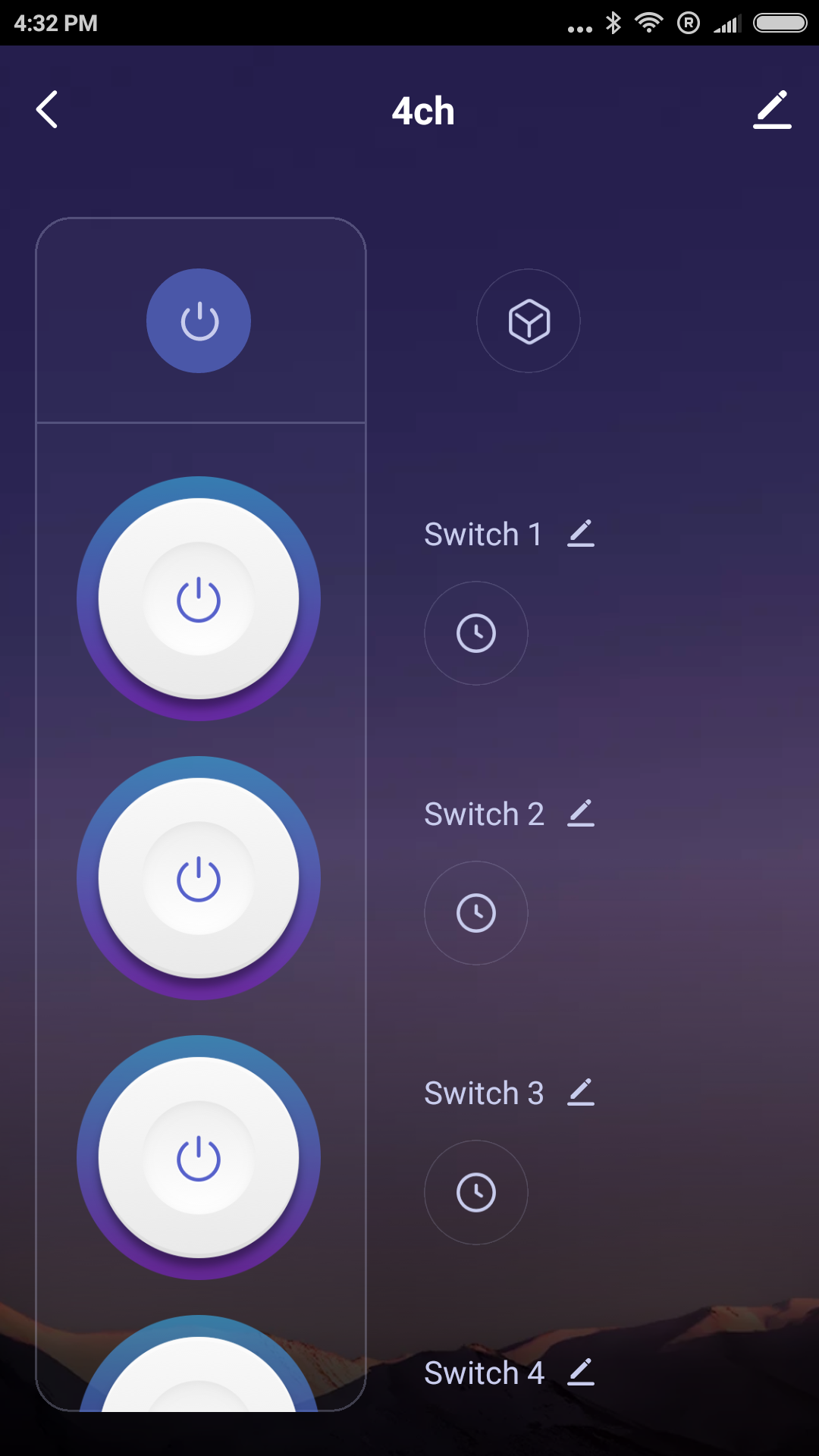
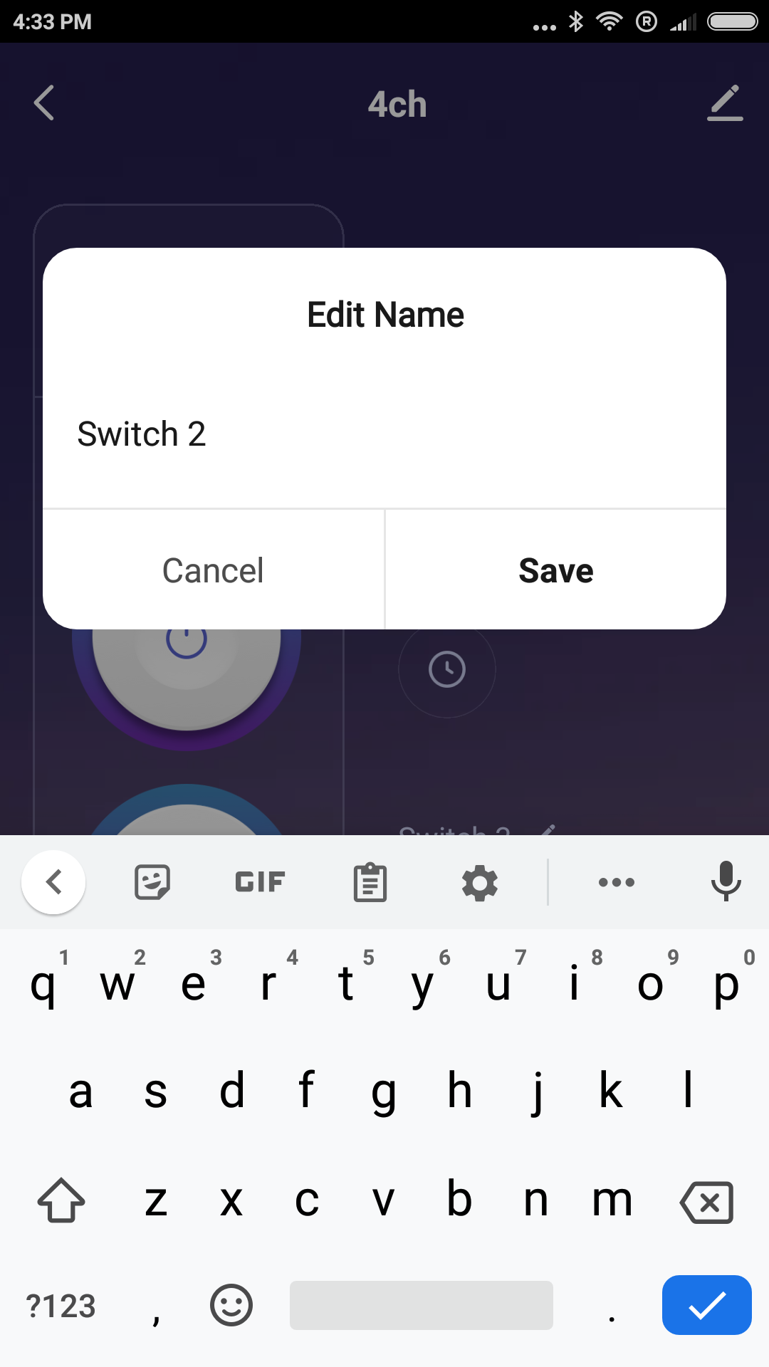
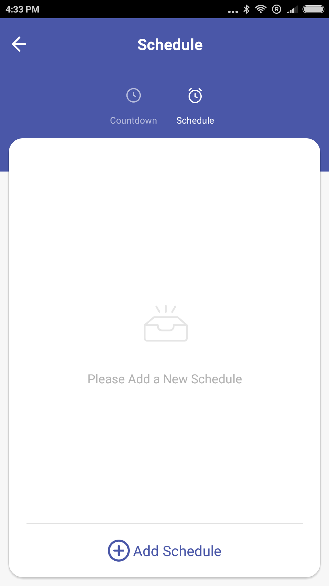
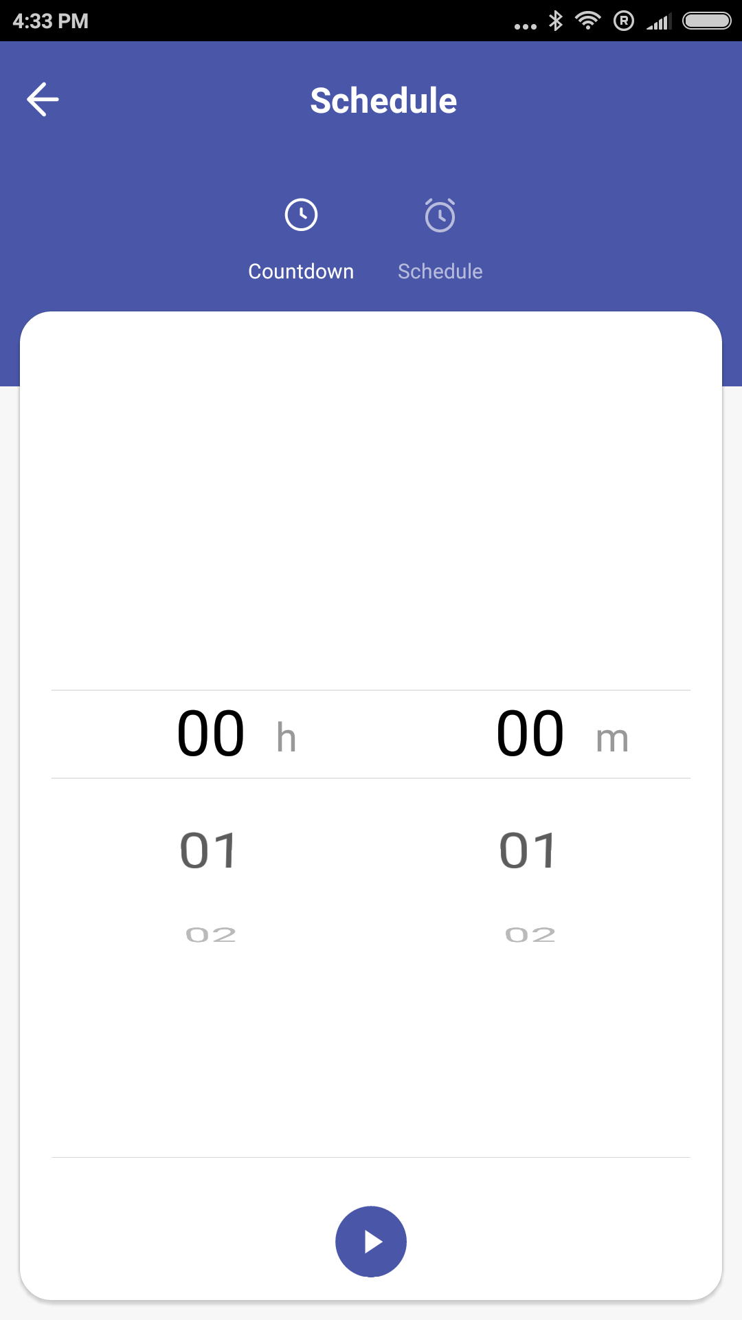
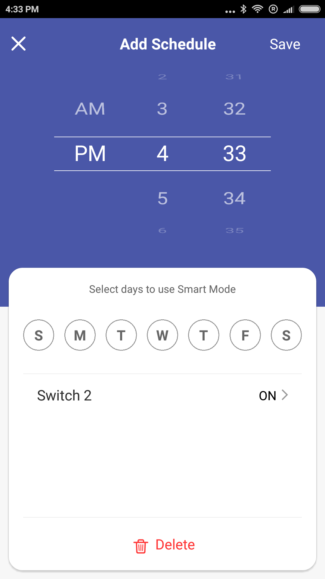
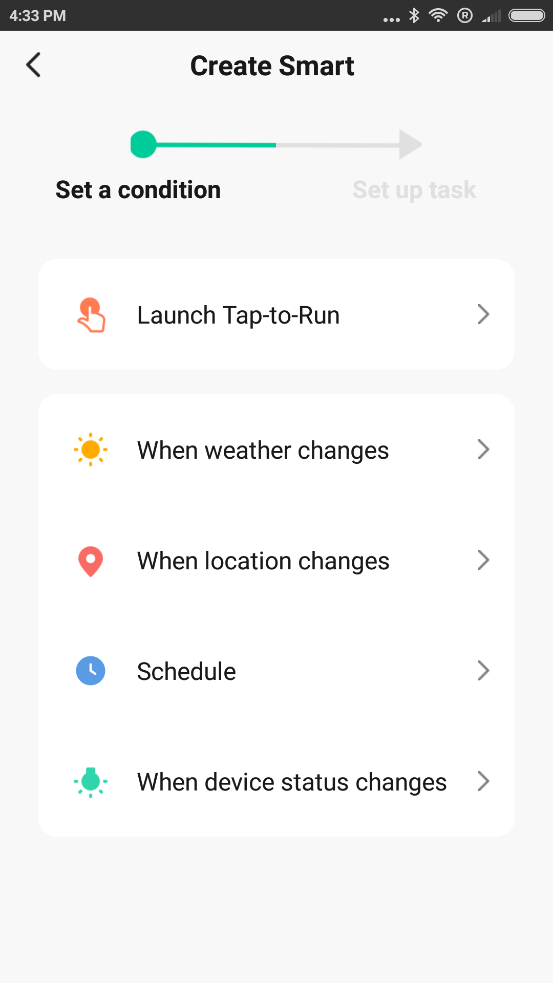
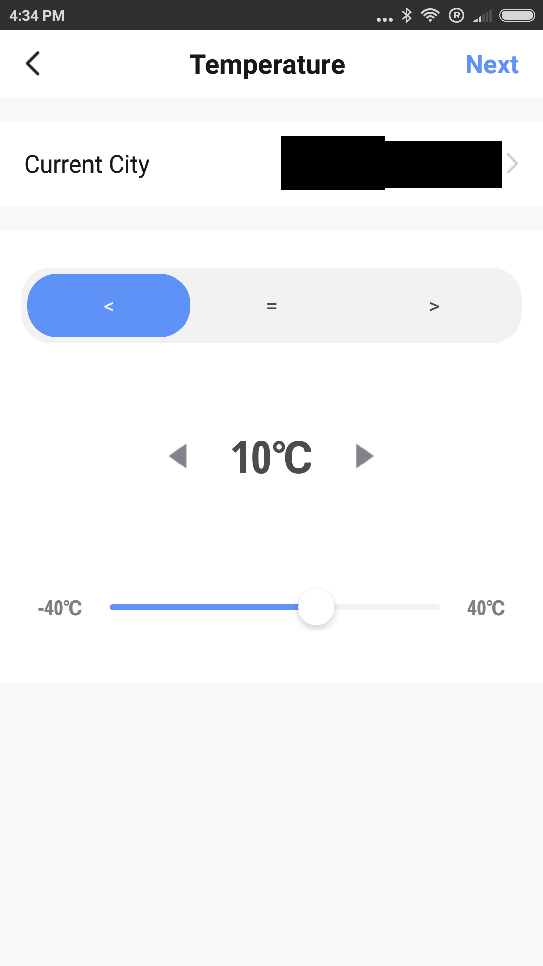
The Tuya application allows you to control each of the relays separately, as well as turn them off / on at once.
A few screenshots from the Tuya mobile app:

 Teardown
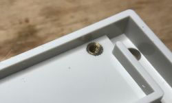
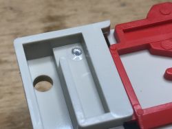
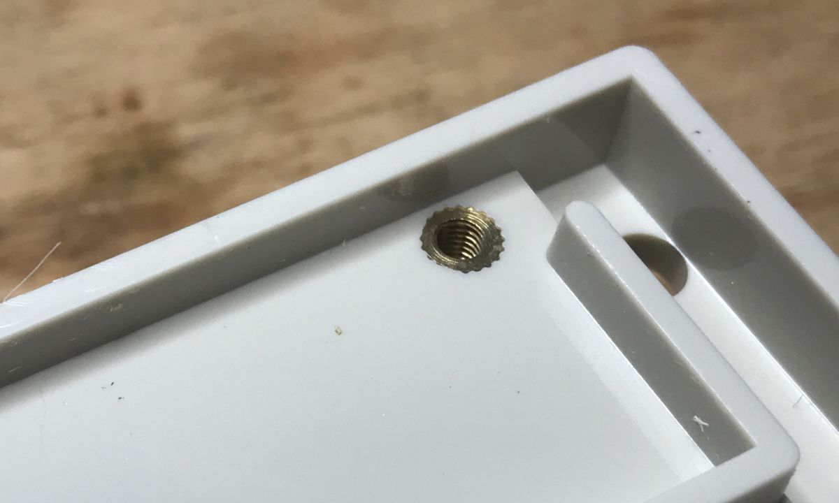
The housing is held on four screws. There was no problem with unscrewing three of them, but I struggled with the fourth. At first I thought it was some kind of protection, but then I got the impression that something was wrong with its mounting:
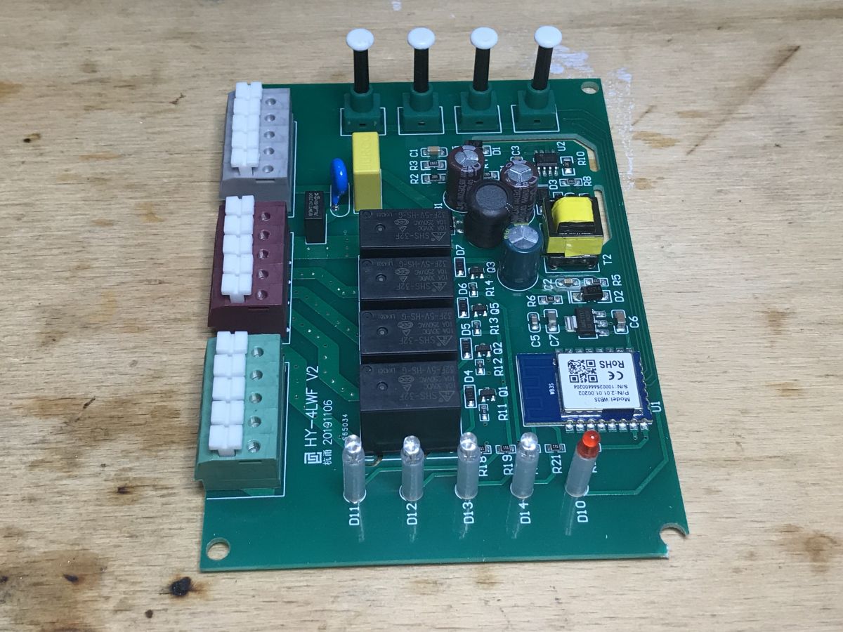
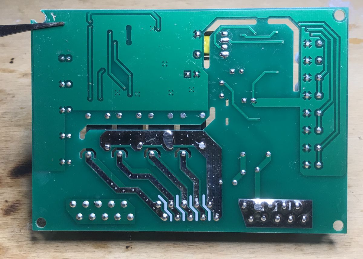
In the end, it was possible to open without major damage (the tile in the corner has only a mass spout, by the way, the whole groundplane, including secondary side ground of the WiFi module is connected to the mains...):

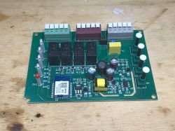

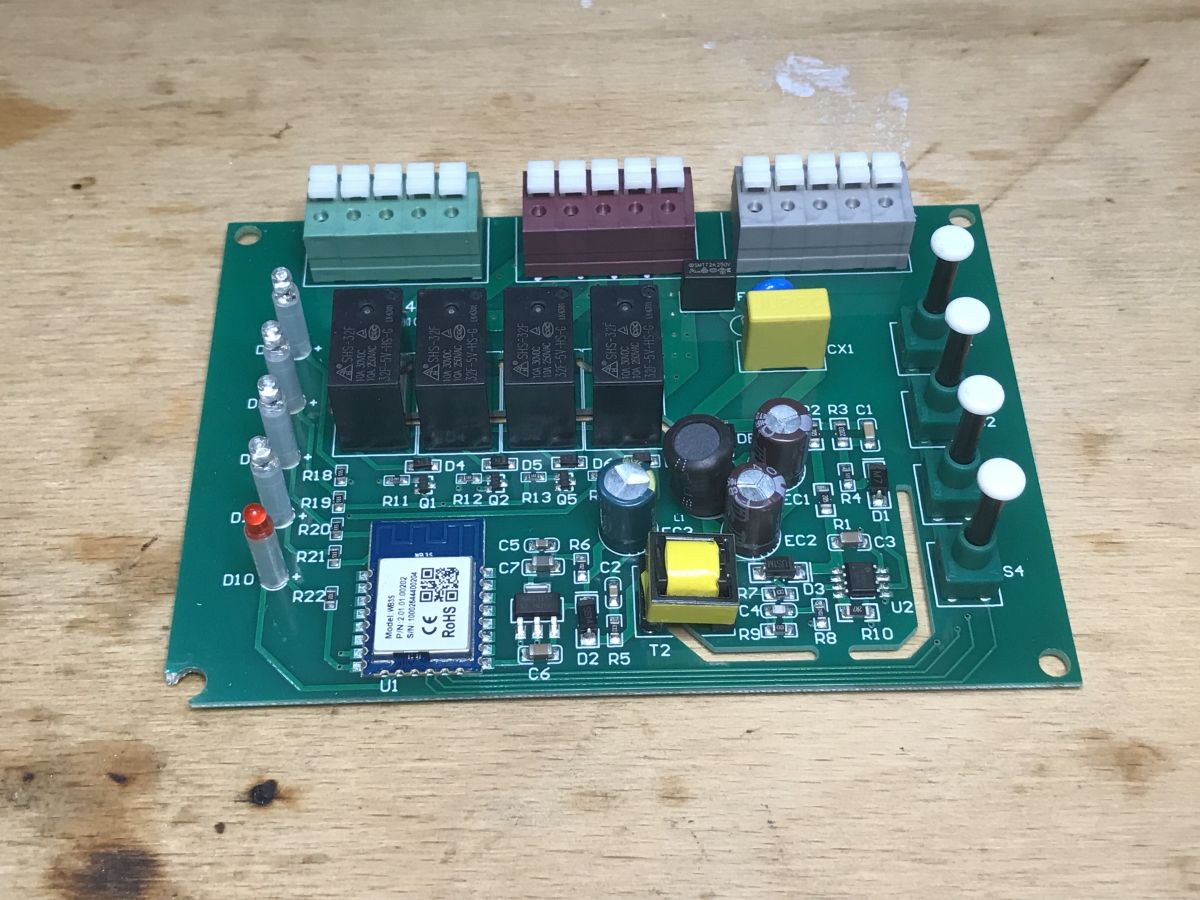
Relays only cut off the phase wire. The groundplane connects the primary and secondary sides, you can see in the photo that the mass reaches up to the mass of the 400V 4.7uF filter capacitor, which is just behind the rectifier bridge.

There is a SMTT2A250V fuse on the input. The 2A rating is definitely a total exaggeration and I do not know why it is there, although maybe I misread the marking:
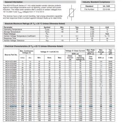
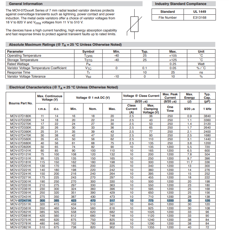
Next is the JK-ET 07D471K varistor, surge protection:
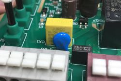
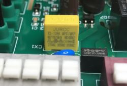
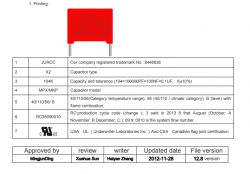
X2 class capacitor (X2 safety class capacitor), against EMI. JURCC X2-104 MPX / MKP:
Produced in China, the manufacturer provides its catalog notes, although they are quite poorly translated into English:
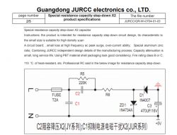
(this "capacity step down" in the diagram from the manufacturer should be called rather "capacitive dropper" and does not reflect what is in the device discussed here, in the discussed device there is a flyback pulse power supply)
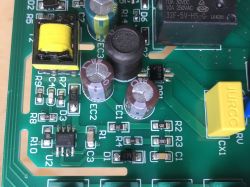
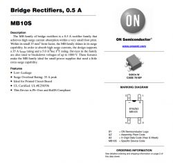
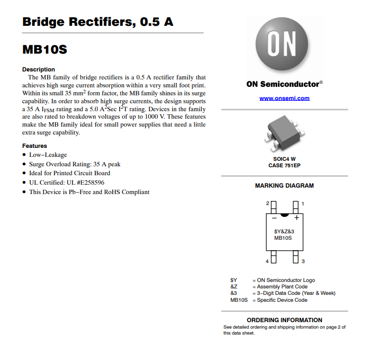
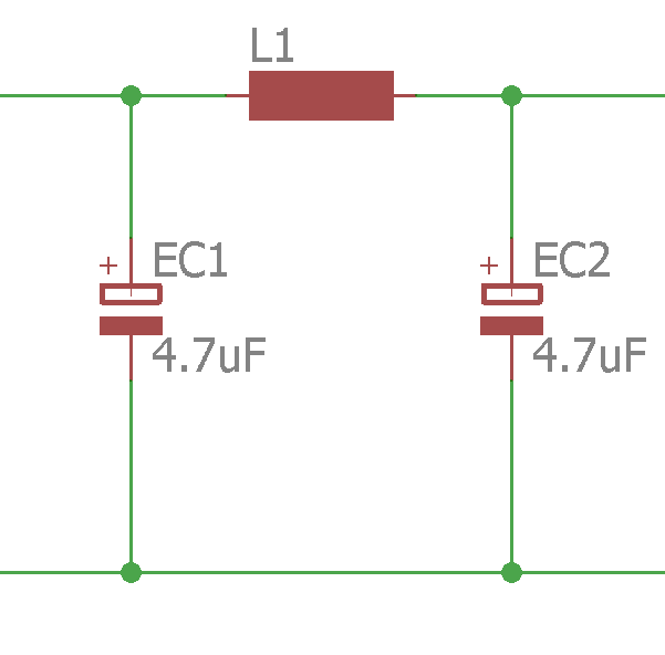
MB10S rectifier bridge. Two electrolytic capacitors at 400V 4.7uF and a choke between them (PI filter). Next, the switching power supply system on the HX5923.

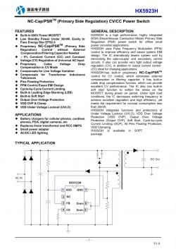
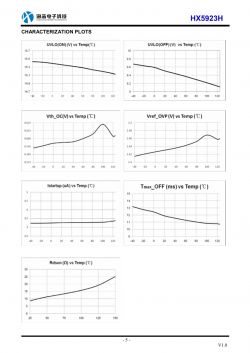
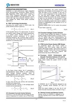
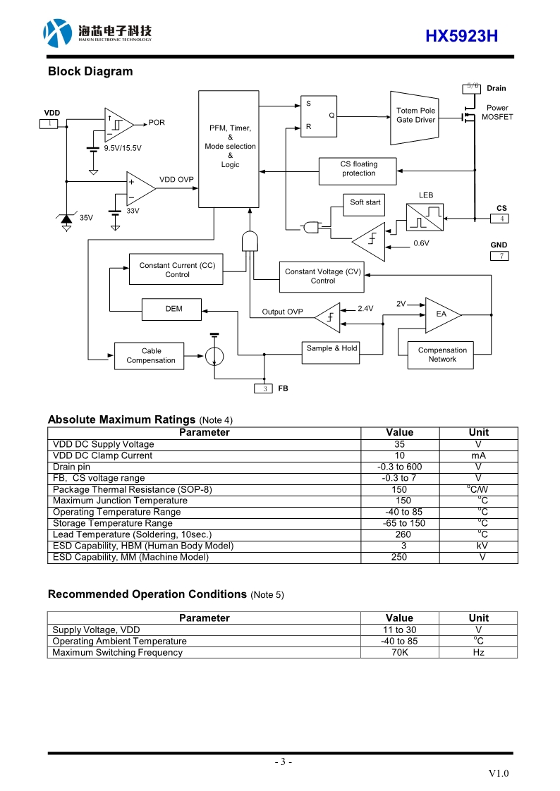
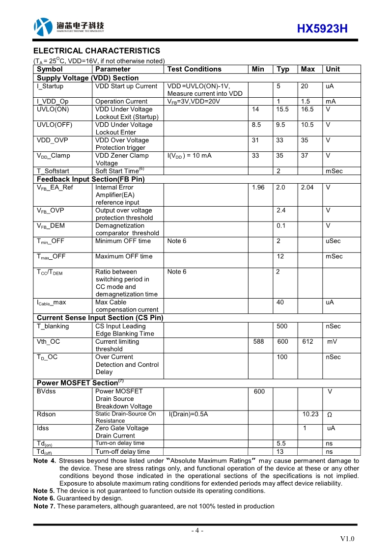
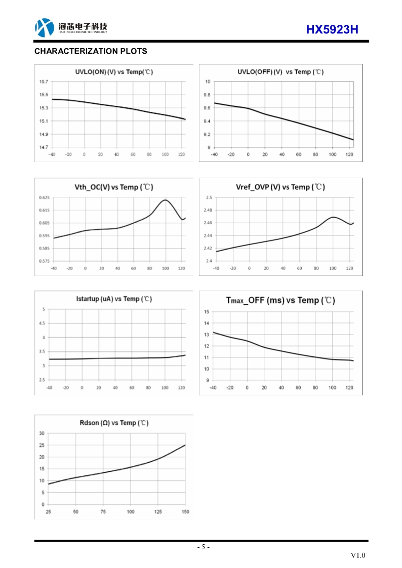
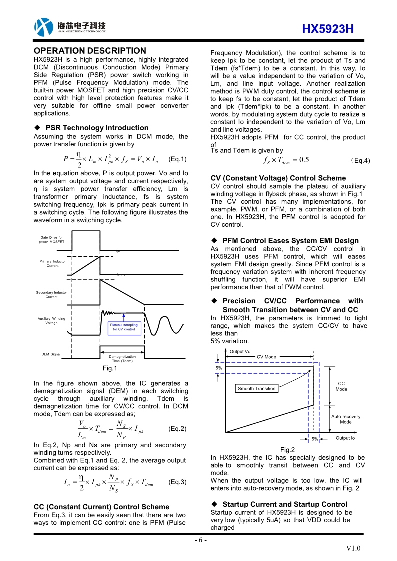
On the manufacturer's website I managed to find a few pages from the HX5923 catalog note (I provide them as images, no pdf file available). HX5923 is a flyback converter controller with built-in MOFSET transistor working in PSR mode (Primary Side Regulation, voltage regulation by feedback through primary auxiliary winding, without optocoupler etc.).
HX5923 pin roles:
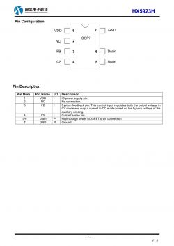
Internal diagram
(also important to realize that e.g. between pins 5/6 - Drain, and pin 4 - CS, Current Sense, there is simply a MOSFET in HX5923):

Characteristics:
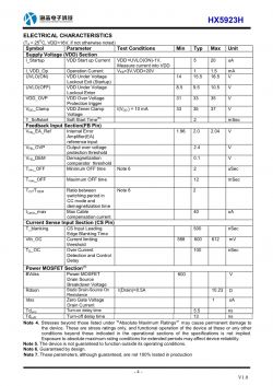
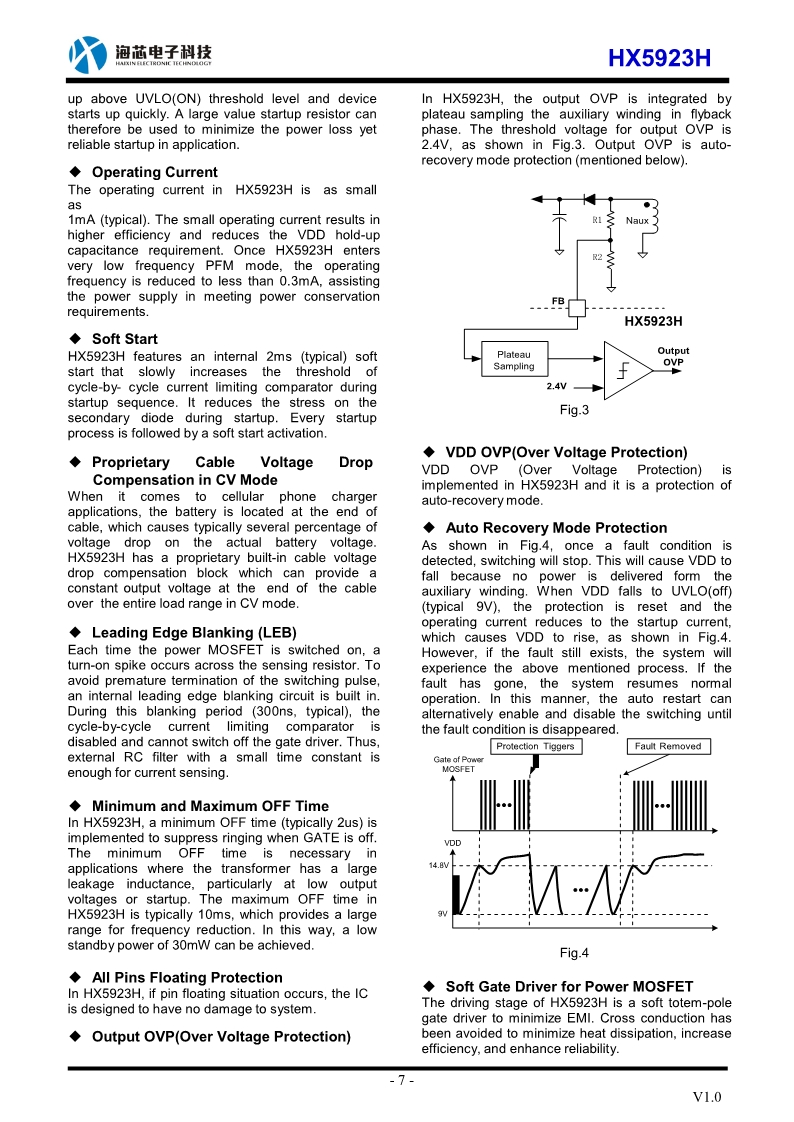
A description of the operation:
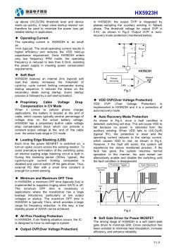
After all, this converter does not provide galvanic separation because the manufacturer, instead of separating the "mass" of low voltage from the "high" one, connected them together (instead of putting a Y-class capacitor between them).
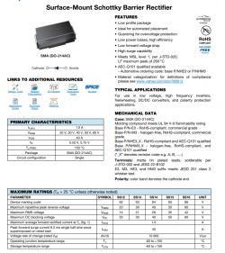
On the side of the secondary winding there is a single Schottky SS14 diode:
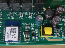
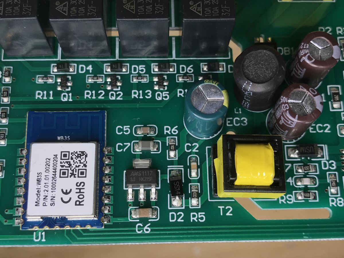
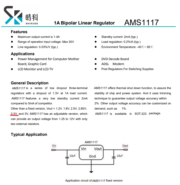
The power supply gives about 5V, there are also relays working at 5V. Next is the LDO regulator AMS1117 3.3 to get 3.3V for the module with WiFi:

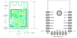
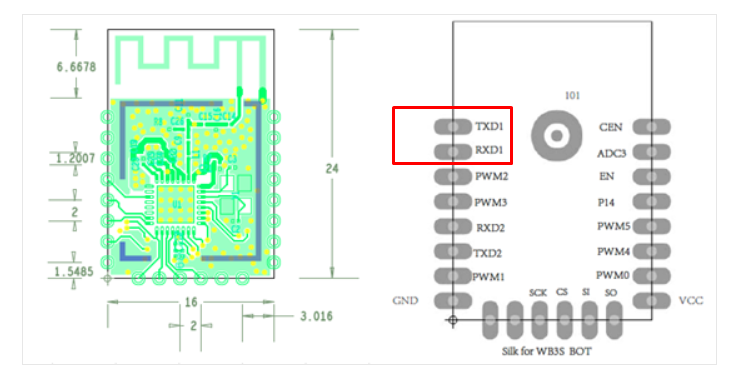
The WiFi module is WB3S (unfortunately it is not based on ESP8266):
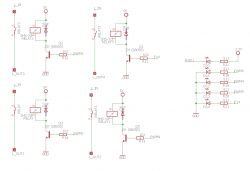
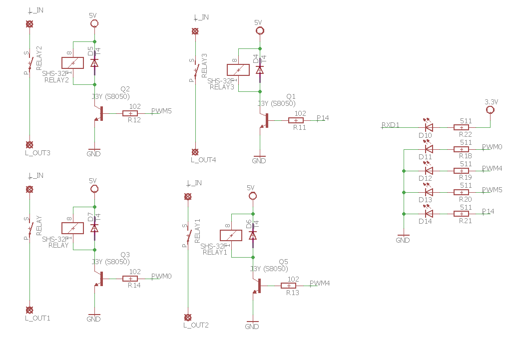
The WB3S controls the relays through transistors. These transistors activate 5V on the relay coil, of course, there is a protective diode parallel to it, so 4 times:
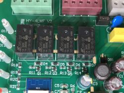
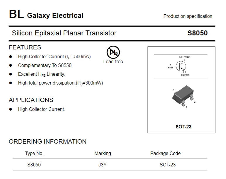
J3Y was used here, or rather S8050.

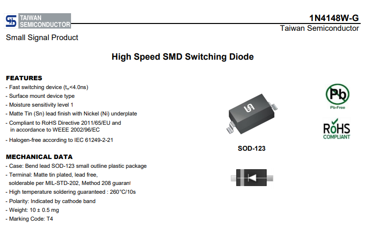
In the role of the 'freewheeling diode' there is a diode marked T4, i.e. probably 1N4148W:

In addition, you can see that the LEDs indicating the status of the relays are on the same WB3S pins as the transistors that control the relays.
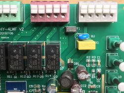
The relays themselves are:
SHS-32F
32F-5V-HS-G
Their supply voltage tells us how much V is before AMS1117.
It's time to draw a diagram.
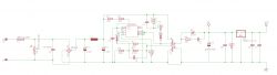
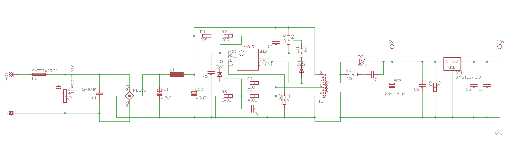
The schematic of Tuya SmartLife 4CH
The markings of the elements correspond to the markings on the board (e.g. EC1, EC2 convention for electrolytic capacitors).
The resistor values are given in the SMD code.
Power section:
A few notes about the scheme:
- F1, the fuse, the current rating is too high, it should be different (but the manufacturer gave it)
- RV - varistor, overvoltage protection
- X1, interference suppression capacitor (against noise emission into the network)
- EC1, L1, EC2 - pi filter
- R1, R2 - resistors with quite high resistance, after connecting the power supply slowly charge C3 so that the converter can start
- R7, D3 - when the inverter is working, the winding ensures charging of C3 so that the inverter can continue to work
- C1, R3, R4, D1 - snubber parallel to the primary winding. I am surprised here by the M7 diode, 1N4007, apparently the manufacturer decided that you do not need fast
- R8 and R9 are a voltage divider for feedback from the converter controller (to the FB - Feedback pin)
- R10 is the so-called a shunt, used to measure the current flowing from the primary winding, is a low-resistance resistor (connected to the CS - Current Sense pin)
For more information, please refer to the included catalog note HX5923.
WiFi module section + buttons:
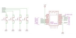
I think the schematic should be easy to interpret, but it is worth emphasizing that the buttons have internal pull-up resistors (programmable in the WB3S itself), and the debouncing is implemented by software.
Relays section:
 Update - OpenBeken and Home Assistant [2022]
[Update - 2022.07.13]
This device, of course, has been supported by my
OpenBeken project for a long time . OpenBeken allows you to disconnect the device from Tuya cloud and control it entirely as you want, of course also providing Home Assistant compatibility, Tasmota Device Groups supports and much more.
I uploaded the firmware through bkWriter 1.60, according to:
Garden Tuya CCWFIO232PK Double Relay - BK7231T - Programming
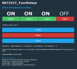
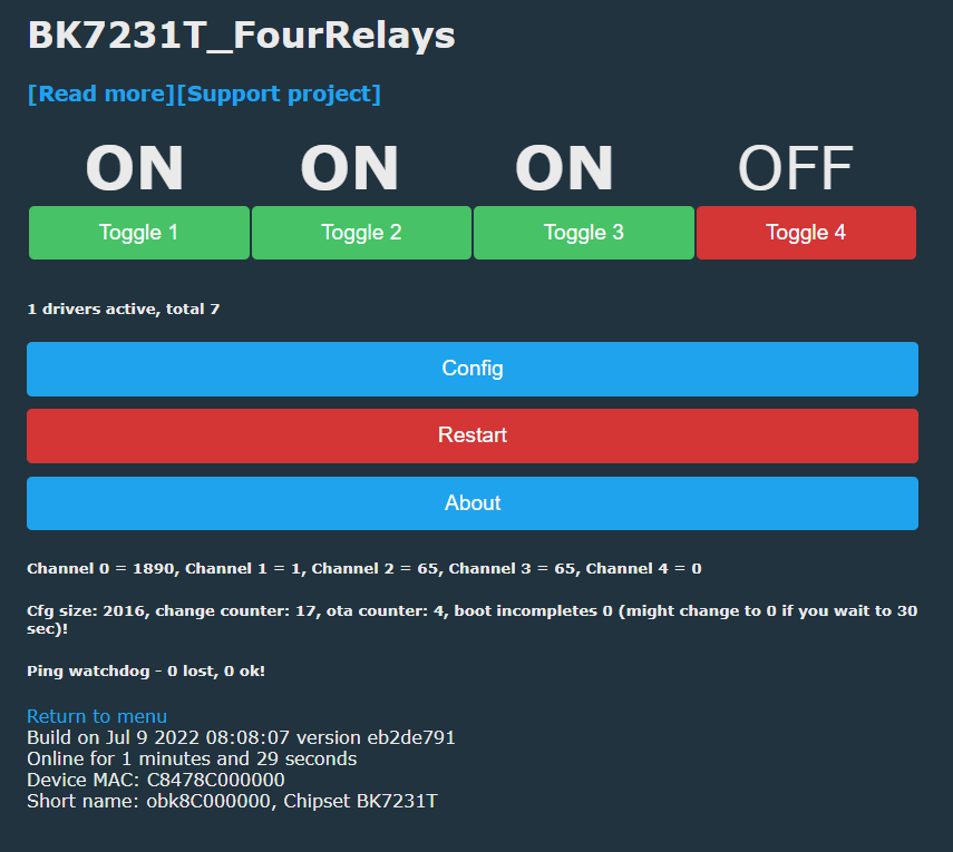
This is how the main panel looks like:
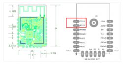
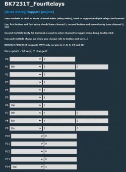
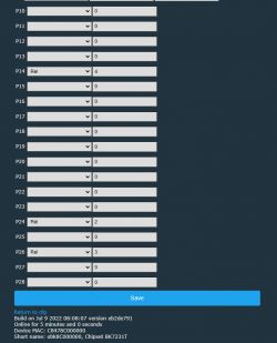
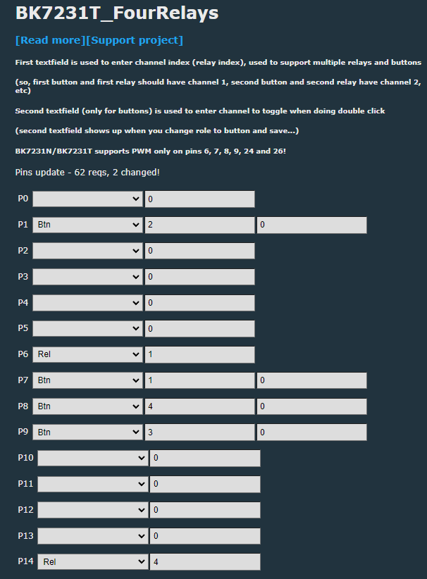
Here is the pin configuration:
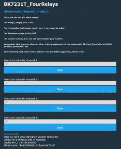
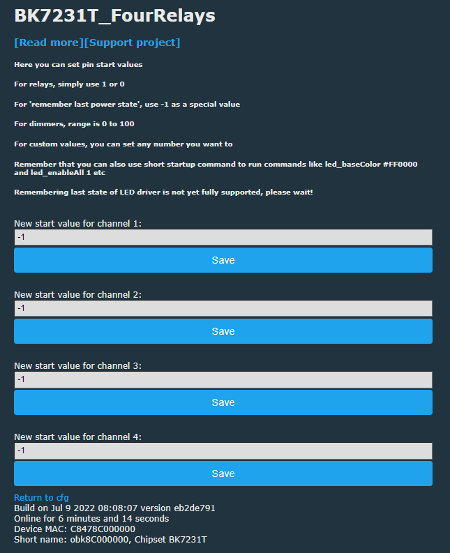
Here is the startup setup (channels remember their state before power loss):
The relay also works with Home Assistant - here is the Yaml configuration (older format, but easy to convert to a newer one):
switch:
  - platform: mqtt
    name: "obk8C000000 1"
    state_topic: "obk8C000000/1/get"
    command_topic: "obk8C000000/1/set"
    qos: 1
    payload_on: 1
    payload_off: 0
    retain: true
    availability_topic: "obk8C000000/connected"
  - platform: mqtt
    name: "obk8C000000 2"
    state_topic: "obk8C000000/2/get"
    command_topic: "obk8C000000/2/set"
    qos: 1
    payload_on: 1
    payload_off: 0
    retain: true
    availability_topic: "obk8C000000/connected"
  - platform: mqtt
    name: "obk8C000000 3"
    state_topic: "obk8C000000/3/get"
    command_topic: "obk8C000000/3/set"
    qos: 1
    payload_on: 1
    payload_off: 0
    retain: true
    availability_topic: "obk8C000000/connected"
  - platform: mqtt
    name: "obk8C000000 4"
    state_topic: "obk8C000000/4/get"
    command_topic: "obk8C000000/4/set"
    qos: 1
    payload_on: 1
    payload_off: 0
    retain: true
    availability_topic: "obk8C000000/connected"
So here we have another product from Tuya that is not based on ESP (there is no TYWE3S, TYWE2S, etc. module). Luckily OpenBeken already supports it well, so there is no need for WiFi module swap.
It is also worth noting that the switching power supply from the inside of this device does not provide galvanic protection, so you should never touch the board (nor connect it to PC) while it's connected to mains!
Other than that, it should be a good and useful 4CH relays controller, especially with OpenBeken. I think I will surely find some use for it at my worplace.


Comments
At first glance, I thought the description was for Sonoff 4ch, because it looks the same on the thumbnail :-) only after opening the full photo and reading the description, I realized that it was something... [Read more]
Today the topic has been updated. I added the information that OpenBeken fully supports this controller and I put some screenshots from the panel. There were no problems with programming, as before, USB... [Read more]